2022 RAM PROMASTER CITY spare tire location
[x] Cancel search: spare tire locationPage 6 of 260

4
MULTIMEDIA
UCONNECT SYSTEMS ........................................... 78
CYBERSECURITY ................................................... 78
UCONNECT SETTINGS .......................................... 79 Uconnect 3/3 NAV Settings .............................79
UCONNECT INTRODUCTION.................................. 88
Identifying Your Radio ......................................88
Safety And General Information ......................90
UCONNECT MODES ............................................... 91
Radio Mode ......................................................91
Media Mode......................................................98
Phone Mode ................................................. 100
NAVIGATION MODE — IF EQUIPPED ..................110
Operating Navigation Mode —If Equipped ... 110
STEERING WHEEL AUDIO CONTROLS —
IF EQUIPPED ........................................................ 128
Radio Operation ............................................ 128
Media Mode................................................... 129
RAM TELEMATICS - IF EQUIPPED ...................... 129
Ram Telematics General Information .......... 129
RADIO OPERATION AND MOBILE PHONES ..... 130
Regulatory And Safety Information .............. 130
SAFETY
SAFETY FEATURES .............................................. 131Four-Wheel Anti-Lock Brake System (ABS).. 131
Electronic Brake Control (EBC) System ...... 132
AUXILIARY DRIVING SYSTEMS.......................... 135
Tire Pressure Monitoring System (TPMS) .... 135
OCCUPANT RESTRAINT SYSTEMS ................... 137
Occupant Restraint Systems ........................ 137
Important Safety Precautions ...................... 137Seat Belt Systems ........................................ 138Supplemental Restraint Systems (SRS) ...... 144Child Restraints ............................................. 152
SAFETY TIPS ....................................................... 168
Transporting Passengers .............................. 168Transporting Pets ......................................... 168
Safety Checks You Should Make Inside
The Vehicle ................................................... 168
Periodic Safety Checks You Should Make
Outside The Vehicle ...................................... 169
Exhaust Gas................................................... 170
Carbon Monoxide Warnings ........................ 170
IN CASE OF EMERGENCY
HAZARD WARNING FLASHERS......................... 171
JACKING AND TIRE CHANGING ......................... 171
Preparations For Jacking ............................. 171
Jack Location — If Equipped ......................... 172
Removing The Spare Tire —If Equipped....... 172 Jacking Instructions ...................................... 174
Vehicles With Alloy Wheels ........................... 177
Vehicles Equipped With Wheel Covers ........ 178
TIRE SERVICE KIT — IF EQUIPPED .................... 179
Tire Service Kit Storage ................................ 179Tire Service Kit Usage ................................... 179
JUMP STARTING .................................................. 181
Preparations For Jump Starting ................... 181Jump Starting Procedure .............................. 182
IF YOUR ENGINE OVERHEATS ........................... 183
IGNITION KEY REMOVAL OVERRIDE ................. 184
GEAR SELECTOR OVERRIDE .............................. 184
FREEING A STUCK VEHICLE .............................. 185
TOWING A DISABLED VEHICLE .......................... 187
ENHANCED ACCIDENT RESPONSE SYSTEM
(EARS) .................................................................. 188
EVENT DATA RECORDER (EDR) ......................... 188
SERVICING AND MAINTENANCE
SCHEDULED SERVICING .................................... 189
Maintenance Plan ......................................... 190
ENGINE COMPARTMENT .................................... 193
Engine Compartment — 2.4L ....................... 193
Checking Oil Level ........................................ 194
Adding Washer Fluid .................................... 194
Maintenance-Free Battery ........................... 194
Pressure Washing ......................................... 195
22_VM_OM_EN_USC_t.book Page 4
Page 174 of 260
172IN CASE OF EMERGENCY
2. Turn on the Hazard Warning Flashers.
3. Apply the parking brake.
4. Place the gear selector into PARK (P).
5. Turn the ignition to the STOP (OFF/LOCK) position.
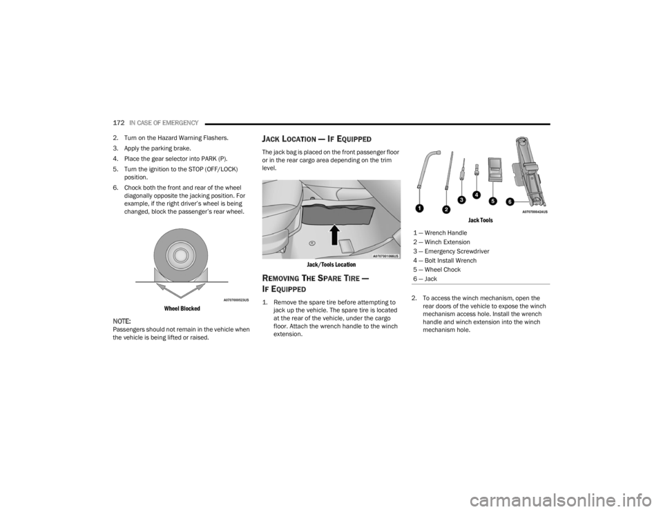
6. Chock both the front and rear of the wheel diagonally opposite the jacking position. For
example, if the right driver’s wheel is being
changed, block the passenger’s rear wheel.
Wheel Blocked
NOTE:Passengers should not remain in the vehicle when
the vehicle is being lifted or raised.
JACK LOCATION — IF EQUIPPED
The jack bag is placed on the front passenger floor
or in the rear cargo area depending on the trim
level.
Jack/Tools Location
REMOVING THE SPARE TIRE —
I
F EQUIPPED
1. Remove the spare tire before attempting to
jack up the vehicle. The spare tire is located
at the rear of the vehicle, under the cargo
floor. Attach the wrench handle to the winch
extension.
Jack Tools
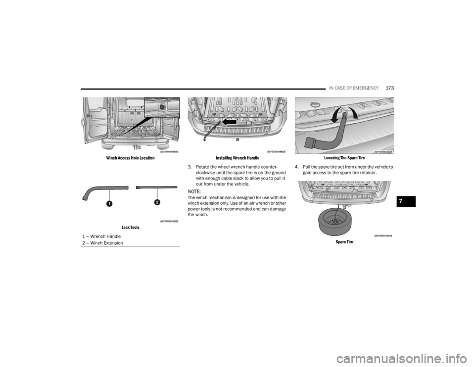
2. To access the winch mechanism, open the rear doors of the vehicle to expose the winch
mechanism access hole. Install the wrench
handle and winch extension into the winch
mechanism hole.
1 — Wrench Handle
2 — Winch Extension
3 — Emergency Screwdriver
4 — Bolt Install Wrench
5 — Wheel Chock
6 — Jack
22_VM_OM_EN_USC_t.book Page 172
Page 175 of 260
IN CASE OF EMERGENCY173
Winch Access Hole Location Jack Tools Installing Wrench Handle
3. Rotate the wheel wrench handle counter -
clockwise until the spare tire is on the ground
with enough cable slack to allow you to pull it
out from under the vehicle.
NOTE:The winch mechanism is designed for use with the
winch extension only. Use of an air wrench or other
power tools is not recommended and can damage
the winch.
Lowering The Spare Tire
4. Pull the spare tire out from under the vehicle to gain access to the spare tire retainer.
Spare Tire
1 — Wrench Handle
2 — Winch Extension7
22_VM_OM_EN_USC_t.book Page 173
Page 176 of 260
174IN CASE OF EMERGENCY
(Continued)
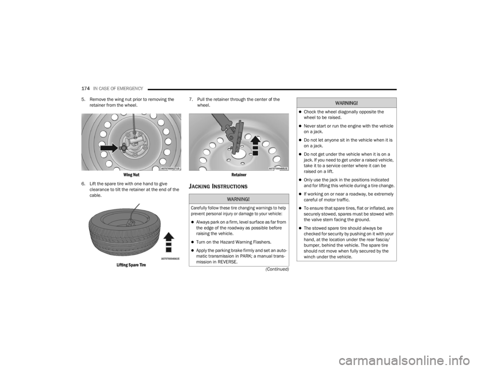
5. Remove the wing nut prior to removing the
retainer from the wheel.
Wing Nut
6. Lift the spare tire with one hand to give clearance to tilt the retainer at the end of the
cable.
Lifting Spare Tire
7. Pull the retainer through the center of the
wheel.
Retainer
JACKING INSTRUCTIONS
WARNING!
Carefully follow these tire changing warnings to help
prevent personal injury or damage to your vehicle:
Always park on a firm, level surface as far from
the edge of the roadway as possible before
raising the vehicle.
Turn on the Hazard Warning Flashers.
Apply the parking brake firmly and set an auto -
matic transmission in PARK; a manual trans -
mission in REVERSE.
Chock the wheel diagonally opposite the
wheel to be raised.
Never start or run the engine with the vehicle
on a jack.
Do not let anyone sit in the vehicle when it is
on a jack.
Do not get under the vehicle when it is on a
jack. If you need to get under a raised vehicle,
take it to a service center where it can be
raised on a lift.
Only use the jack in the positions indicated
and for lifting this vehicle during a tire change.
If working on or near a roadway, be extremely
careful of motor traffic.
To ensure that spare tires, flat or inflated, are
securely stowed, spares must be stowed with
the valve stem facing the ground.
The stowed spare tire should always be
checked for security by pushing on it with your
hand, at the location under the rear fascia/
bumper, behind the vehicle. The spare tire
should not move when fully secured by the
winch under the vehicle.
WARNING!
22_VM_OM_EN_USC_t.book Page 174
Page 178 of 260
176IN CASE OF EMERGENCY
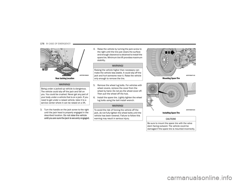
Rear Jacking Location
3. Turn the handle on the jack screw to the right until the jack head is properly engaged in the
described location. Do not raise the vehicle
until you are sure the jack is securely engaged. 4. Raise the vehicle by turning the jack screw to
the right until the tire just clears the surface
and enough clearance is obtained to install the
spare tire. Minimum tire lift provides maximum
stability.
5. Remove the wheel lug bolts. For vehicles with wheel covers, remove the cover from the
wheel by hand. Do not pry the wheel cover off.
Then pull the wheel off the hub.
6. Install the spare tire. Lightly tighten the wheel lug bolts using the bolt install wrench.
Mounting Spare Tire
Installing Spare Tire
WARNING!
Being under a jacked-up vehicle is dangerous.
The vehicle could slip off the jack and fall on
you. You could be crushed. Never get any part of
your body under a vehicle that is on a jack. If you
need to get under a raised vehicle, take it to a
service center where it can be raised on a lift.
WARNING!
Raising the vehicle higher than necessary can
make the vehicle less stable. It could slip off the
jack and hurt someone near it. Raise the vehicle
only enough to remove the tire.
WARNING!
To avoid the risk of forcing the vehicle off the
jack, do not fully tighten the wheel bolts until the
vehicle has been lowered. Failure to follow this
warning may result in serious injury.
CAUTION!
Be sure to mount the spare tire with the valve
stem facing outward. The vehicle could be
damaged if the spare tire is mounted incorrectly.
22_VM_OM_EN_USC_t.book Page 176
Page 223 of 260
SERVICING AND MAINTENANCE221
Tire Terminology And Definitions
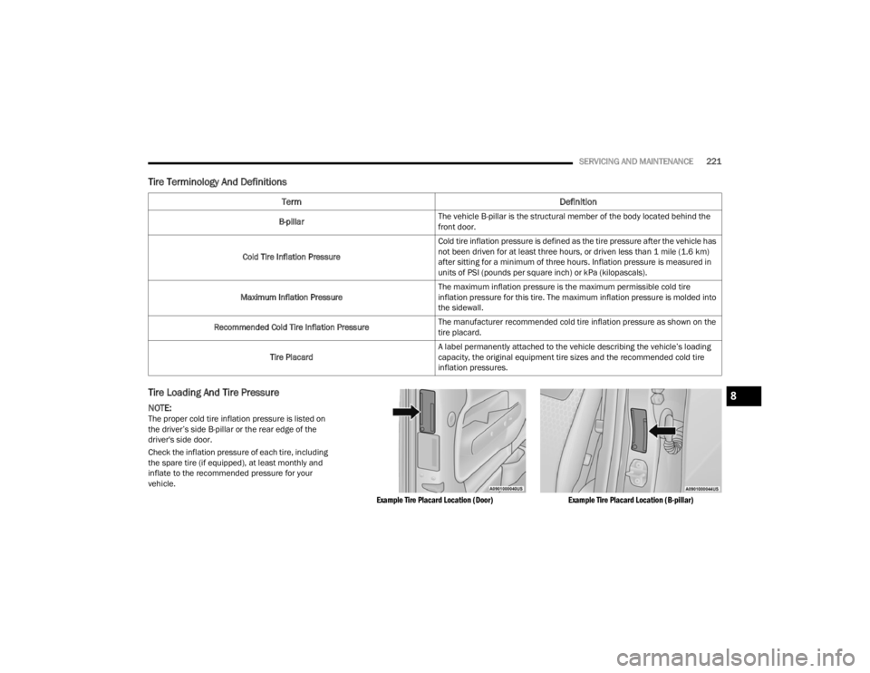
Tire Loading And Tire Pressure
NOTE:The proper cold tire inflation pressure is listed on
the driver’s side B-pillar or the rear edge of the
driver's side door.
Check the inflation pressure of each tire, including
the spare tire (if equipped), at least monthly and
inflate to the recommended pressure for your
vehicle.
Example Tire Placard Location (Door)Example Tire Placard Location (B-pillar)
Term Definition
B-pillarThe vehicle B-pillar is the structural member of the body located behind the
front door.
Cold Tire Inflation Pressure Cold tire inflation pressure is defined as the tire pressure after the vehicle has
not been driven for at least three hours, or driven less than 1 mile (1.6 km)
after sitting for a minimum of three hours. Inflation pressure is measured in
units of PSI (pounds per square inch) or kPa (kilopascals).
Maximum Inflation Pressure The maximum inflation pressure is the maximum permissible cold tire
inflation pressure for this tire. The maximum inflation pressure is molded into
the sidewall.
Recommended Cold Tire Inflation Pressure The manufacturer recommended cold tire inflation pressure as shown on the
tire placard.
Tire Placard A label permanently attached to the vehicle describing the vehicle’s loading
capacity, the original equipment tire sizes and the recommended cold tire
inflation pressures.
8
22_VM_OM_EN_USC_t.book Page 221