2022 RAM PROMASTER CITY tow
[x] Cancel search: towPage 5 of 260

3
TRIP COMPUTER .................................................... 43 Trip Button ........................................................43
Trip Functions ..................................................43
Values Displayed ..............................................44
WARNING LIGHTS AND MESSAGES ................... 44
Red Warning Lights ..........................................44
Yellow Warning Lights ......................................47
Green Indicator Lights......................................49
Blue Indicator Lights ........................................50
White Indicator Lights ......................................50
ONBOARD DIAGNOSTIC SYSTEM — OBD II ....... 50
Onboard Diagnostic System
(OBD II) Cybersecurity ......................................51
EMISSIONS INSPECTION AND MAINTENANCE
PROGRAMS ............................................................ 51
STARTING AND OPERATING
STARTING THE ENGINE ........................................ 52
Automatic Transmission ..................................52
Normal Starting ................................................52
Cold Weather Operation .................................52
Extended Park Starting ....................................52
If Engine Fails To Start .....................................53
After Starting.....................................................53
ENGINE BLOCK HEATER — IF EQUIPPED ............ 53
ENGINE BREAK-IN RECOMMENDATIONS .......... 54
PARKING BRAKE .................................................. 54 AUTOMATIC TRANSMISSION ...............................55
Key Ignition Park Interlock...............................56
Brake/Transmission Shift Interlock (BTSI)
System .............................................................56
9-Speed Automatic Transmission ..................56
POWER STEERING ................................................60
Power Steering Fluid Check ............................60
CRUISE CONTROL — IF EQUIPPED .......................60
To Activate ........................................................61
To Set A Desired Speed ...................................61
To Vary The Speed Setting...............................61
To Accelerate For Passing ...............................61
To Resume Speed ............................................62
To Deactivate ...................................................62
PARKSENSE REAR PARK ASSIST —
IF EQUIPPED ...........................................................62
ParkSense Rear Park Assist Sensors .............62
ParkSense Rear Park Assist Alerts .................63
ParkSense Rear Park Assist Failure
Indications ........................................................64
Cleaning The ParkSense Rear Park Assist
System ..............................................................64
ParkSense Rear Park Assist System Usage
Precautions.......................................................64
PARKVIEW REAR BACK UP CAMERA .................65
REFUELING THE VEHICLE .....................................66 VEHICLE LOADING ................................................. 67
Vehicle Certification Label............................... 67
Gross Vehicle Weight Rating (GVWR) ............. 67
Gross Axle Weight Rating (GAWR) .................. 67
Tire Size ............................................................ 67
Rim Size ............................................................ 67
Inflation Pressure ............................................. 67
Curb Weight ...................................................... 67
Overloading ...................................................... 68
Loading ............................................................ 68
TRAILER TOWING .................................................. 68
Common Towing Definitions............................ 68
Trailer Hitch Classification............................... 70
Trailer Towing Weights (Maximum Trailer
Weight Ratings) ............................................... 71
Trailer And Tongue Weight .............................71
Towing Requirements ..................................... 71
Towing Tips ...................................................... 74
RECREATIONAL TOWING
(BEHIND MOTORHOME) ....................................... 75
Towing This Vehicle Behind Another Vehicle .... 75
Recreational Towing — Automatic Transmission .. 76
DRIVING TIPS ......................................................... 76
Driving On Slippery Surfaces .......................... 76
Driving Through Water ....................................76
22_VM_OM_EN_USC_t.book Page 3
Page 6 of 260

4
MULTIMEDIA
UCONNECT SYSTEMS ........................................... 78
CYBERSECURITY ................................................... 78
UCONNECT SETTINGS .......................................... 79 Uconnect 3/3 NAV Settings .............................79
UCONNECT INTRODUCTION.................................. 88
Identifying Your Radio ......................................88
Safety And General Information ......................90
UCONNECT MODES ............................................... 91
Radio Mode ......................................................91
Media Mode......................................................98
Phone Mode ................................................. 100
NAVIGATION MODE — IF EQUIPPED ..................110
Operating Navigation Mode —If Equipped ... 110
STEERING WHEEL AUDIO CONTROLS —
IF EQUIPPED ........................................................ 128
Radio Operation ............................................ 128
Media Mode................................................... 129
RAM TELEMATICS - IF EQUIPPED ...................... 129
Ram Telematics General Information .......... 129
RADIO OPERATION AND MOBILE PHONES ..... 130
Regulatory And Safety Information .............. 130
SAFETY
SAFETY FEATURES .............................................. 131Four-Wheel Anti-Lock Brake System (ABS).. 131
Electronic Brake Control (EBC) System ...... 132
AUXILIARY DRIVING SYSTEMS.......................... 135
Tire Pressure Monitoring System (TPMS) .... 135
OCCUPANT RESTRAINT SYSTEMS ................... 137
Occupant Restraint Systems ........................ 137
Important Safety Precautions ...................... 137Seat Belt Systems ........................................ 138Supplemental Restraint Systems (SRS) ...... 144Child Restraints ............................................. 152
SAFETY TIPS ....................................................... 168
Transporting Passengers .............................. 168Transporting Pets ......................................... 168
Safety Checks You Should Make Inside
The Vehicle ................................................... 168
Periodic Safety Checks You Should Make
Outside The Vehicle ...................................... 169
Exhaust Gas................................................... 170
Carbon Monoxide Warnings ........................ 170
IN CASE OF EMERGENCY
HAZARD WARNING FLASHERS......................... 171
JACKING AND TIRE CHANGING ......................... 171
Preparations For Jacking ............................. 171
Jack Location — If Equipped ......................... 172
Removing The Spare Tire —If Equipped....... 172 Jacking Instructions ...................................... 174
Vehicles With Alloy Wheels ........................... 177
Vehicles Equipped With Wheel Covers ........ 178
TIRE SERVICE KIT — IF EQUIPPED .................... 179
Tire Service Kit Storage ................................ 179Tire Service Kit Usage ................................... 179
JUMP STARTING .................................................. 181
Preparations For Jump Starting ................... 181Jump Starting Procedure .............................. 182
IF YOUR ENGINE OVERHEATS ........................... 183
IGNITION KEY REMOVAL OVERRIDE ................. 184
GEAR SELECTOR OVERRIDE .............................. 184
FREEING A STUCK VEHICLE .............................. 185
TOWING A DISABLED VEHICLE .......................... 187
ENHANCED ACCIDENT RESPONSE SYSTEM
(EARS) .................................................................. 188
EVENT DATA RECORDER (EDR) ......................... 188
SERVICING AND MAINTENANCE
SCHEDULED SERVICING .................................... 189
Maintenance Plan ......................................... 190
ENGINE COMPARTMENT .................................... 193
Engine Compartment — 2.4L ....................... 193
Checking Oil Level ........................................ 194
Adding Washer Fluid .................................... 194
Maintenance-Free Battery ........................... 194
Pressure Washing ......................................... 195
22_VM_OM_EN_USC_t.book Page 4
Page 15 of 260
GETTING TO KNOW YOUR VEHICLE13
NOTE:When opening the driver’s door with the key in the
ignition and the ignition placed in the STOP (OFF/
LOCK) position, a chime will sound to remind you to
remove the key.
DOORS
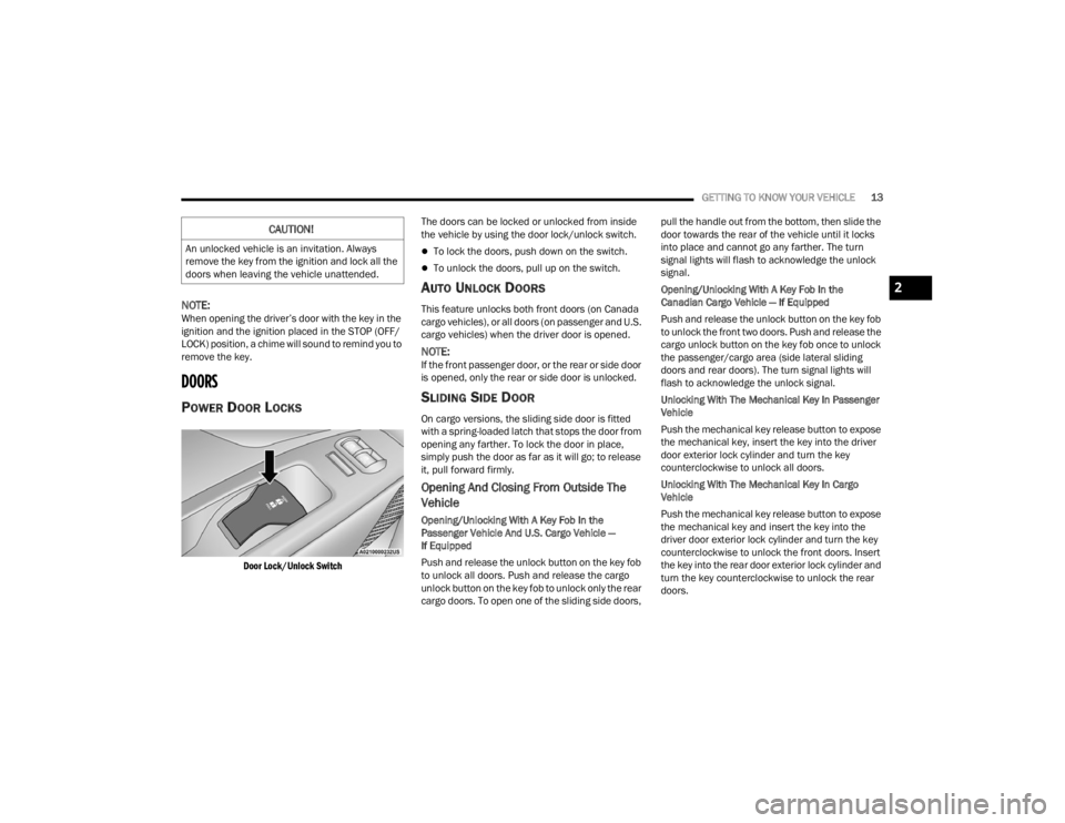
POWER DOOR LOCKS
Door Lock/Unlock Switch
The doors can be locked or unlocked from inside
the vehicle by using the door lock/unlock switch.
To lock the doors, push down on the switch.
To unlock the doors, pull up on the switch.
AUTO UNLOCK DOORS
This feature unlocks both front doors (on Canada
cargo vehicles), or all doors (on passenger and U.S.
cargo vehicles) when the driver door is opened.
NOTE:If the front passenger door, or the rear or side door
is opened, only the rear or side door is unlocked.
SLIDING SIDE DOOR
On cargo versions, the sliding side door is fitted
with a spring-loaded latch that stops the door from
opening any farther. To lock the door in place,
simply push the door as far as it will go; to release
it, pull forward firmly.
Opening And Closing From Outside The
Vehicle
Opening/Unlocking With A Key Fob In the
Passenger Vehicle And U.S. Cargo Vehicle —
If Equipped
Push and release the unlock button on the key fob
to unlock all doors. Push and release the cargo
unlock button on the key fob to unlock only the rear
cargo doors. To open one of the sliding side doors, pull the handle out from the bottom, then slide the
door towards the rear of the vehicle until it locks
into place and cannot go any farther. The turn
signal lights will flash to acknowledge the unlock
signal.
Opening/Unlocking With A Key Fob In the
Canadian Cargo Vehicle — If Equipped
Push and release the unlock button on the key fob
to unlock the front two doors. Push and release the
cargo unlock button on the key fob once to unlock
the passenger/cargo area (side lateral sliding
doors and rear doors). The turn signal lights will
flash to acknowledge the unlock signal.
Unlocking With The Mechanical Key In Passenger
Vehicle
Push the mechanical key release button to expose
the mechanical key, insert the key into the driver
door exterior lock cylinder and turn the key
counterclockwise to unlock all doors.
Unlocking With The Mechanical Key In Cargo
Vehicle
Push the mechanical key release button to expose
the mechanical key and insert the key into the
driver door exterior lock cylinder and turn the key
counterclockwise to unlock the front doors. Insert
the key into the rear door exterior lock cylinder and
turn the key counterclockwise to unlock the rear
doors.
CAUTION!
An unlocked vehicle is an invitation. Always
remove the key from the ignition and lock all the
doors when leaving the vehicle unattended.
2
22_VM_OM_EN_USC_t.book Page 13
Page 16 of 260
14GETTING TO KNOW YOUR VEHICLE
Closing/Locking With A Key Fob
Push and release the lock button on the key fob to
lock all doors, including the cargo area (side lateral
sliding doors and rear doors). The turn signal lights
will flash to acknowledge the lock signal.
Horn activation settings after a key fob lock
command can be adjusted manually through the
Uconnect system Ú page 79.
Locking With The Mechanical Key In Passenger
Vehicle
Push the mechanical key release button to expose
the mechanical key, insert the key into the driver
door exterior lock cylinder and turn the key
clockwise to lock all doors.
Locking With The Mechanical Key In Cargo Vehicle
Push the mechanical key release button to expose
the mechanical key, insert the key into the driver
door exterior lock cylinder and turn the key
clockwise to lock the front doors. Insert the key into
the rear door exterior lock cylinder and turn the key
clockwise to lock the rear doors.
Closing And Locking From Outside
Grab the side door handle and push towards the
front of the vehicle. Once the side door is secured
in the full closed position, use one of the prior
locking methods to lock the sliding side doors.
Opening And Closing From The Inside
Opening:
Pull the interior door handle to unlock the door,
then pull the handle and slide the door towards the
rear of the vehicle until it can go no farther.
Closing:
Pull the interior door handle to release the door
and then push it towards the front of the vehicle.
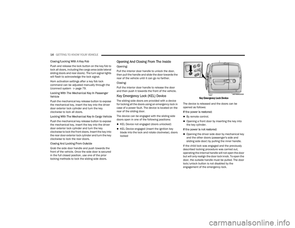
Key Emergency Lock (KEL) Device
The sliding side doors are provided with a device
for locking all the doors using an emergency lock in
case of a power fault. The device is located on the
rear of the sliding door.
The device can be engaged with the sliding side
doors open in one of the following positions:
KEL Device not engaged (doors unlocked)
KEL Device engaged (insert the ignition key
blade into the lock and rotate clockwise), doors
locked
Key Emergency Lock Device
The device is released and the doors can be
opened as follows:
If the power is restored:
By remote control.
Opening a front door by inserting the key into
the key cylinder.
If the power is not restored:
Opening the driver side door by mechanical key
and the other doors (passenger's side and
sliding side door) by pulling the inner handle.
If the child lock was engaged and the previously
described locking procedure was carried out,
operating the internal handle will not open the door
but will only realign the door lock knob. To open the
door, the outside handle must be pulled. The door
lock/unlock button is not disabled by the
engagement of the emergency lock.
22_VM_OM_EN_USC_t.book Page 14
Page 17 of 260
GETTING TO KNOW YOUR VEHICLE15
DOUBLE REAR SWING DOORS
The rear double swing doors are fitted through a
fastening system which stops them when they
reach an opening angle of approximately 90
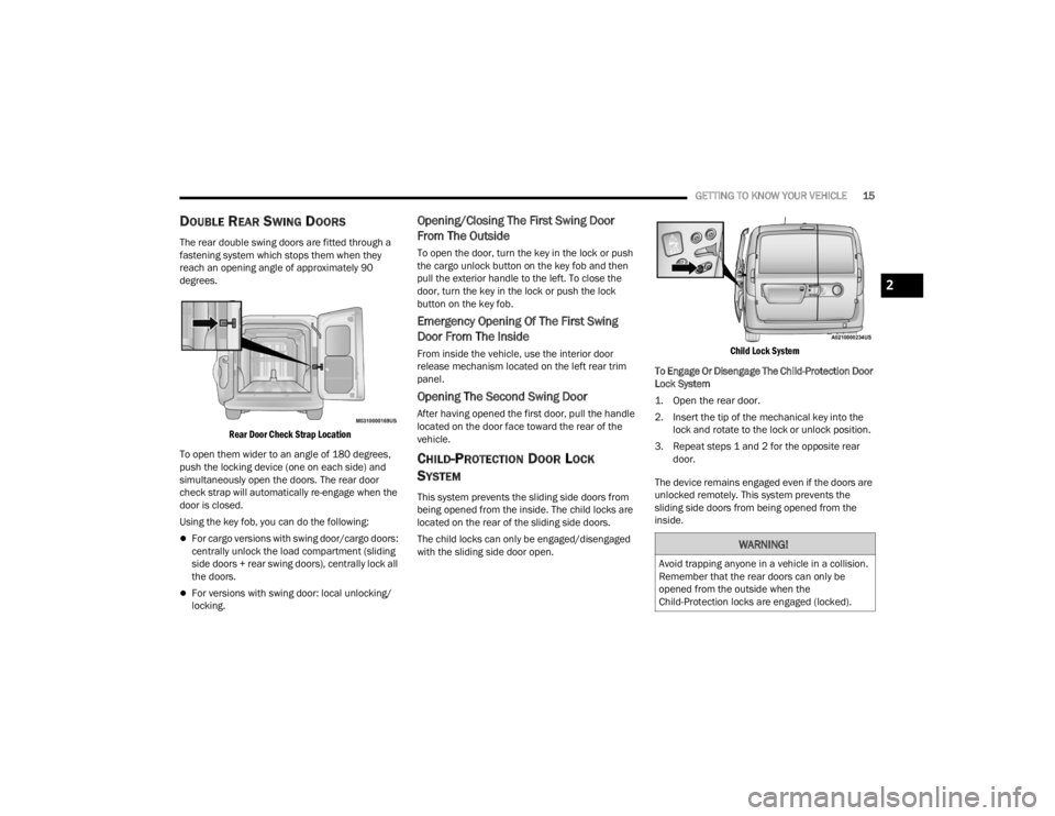
degrees.
Rear Door Check Strap Location
To open them wider to an angle of 180 degrees,
push the locking device (one on each side) and
simultaneously open the doors. The rear door
check strap will automatically re-engage when the
door is closed.
Using the key fob, you can do the following:
For cargo versions with swing door/cargo doors:
centrally unlock the load compartment (sliding
side doors + rear swing doors), centrally lock all
the doors.
For versions with swing door: local unlocking/
locking.
Opening/Closing The First Swing Door
From The Outside
To open the door, turn the key in the lock or push
the cargo unlock button on the key fob and then
pull the exterior handle to the left. To close the
door, turn the key in the lock or push the lock
button on the key fob.
Emergency Opening Of The First Swing
Door From The Inside
From inside the vehicle, use the interior door
release mechanism located on the left rear trim
panel.
Opening The Second Swing Door
After having opened the first door, pull the handle
located on the door face toward the rear of the
vehicle.
CHILD-PROTECTION DOOR LOCK
S
YSTEM
This system prevents the sliding side doors from
being opened from the inside. The child locks are
located on the rear of the sliding side doors.
The child locks can only be engaged/disengaged
with the sliding side door open.
Child Lock System
To Engage Or Disengage The Child-Protection Door
Lock System
1. Open the rear door.
2. Insert the tip of the mechanical key into the lock and rotate to the lock or unlock position.
3. Repeat steps 1 and 2 for the opposite rear door.
The device remains engaged even if the doors are
unlocked remotely. This system prevents the
sliding side doors from being opened from the
inside.
WARNING!
Avoid trapping anyone in a vehicle in a collision.
Remember that the rear doors can only be
opened from the outside when the
Child-Protection locks are engaged (locked).
2
22_VM_OM_EN_USC_t.book Page 15
Page 22 of 260
20GETTING TO KNOW YOUR VEHICLE
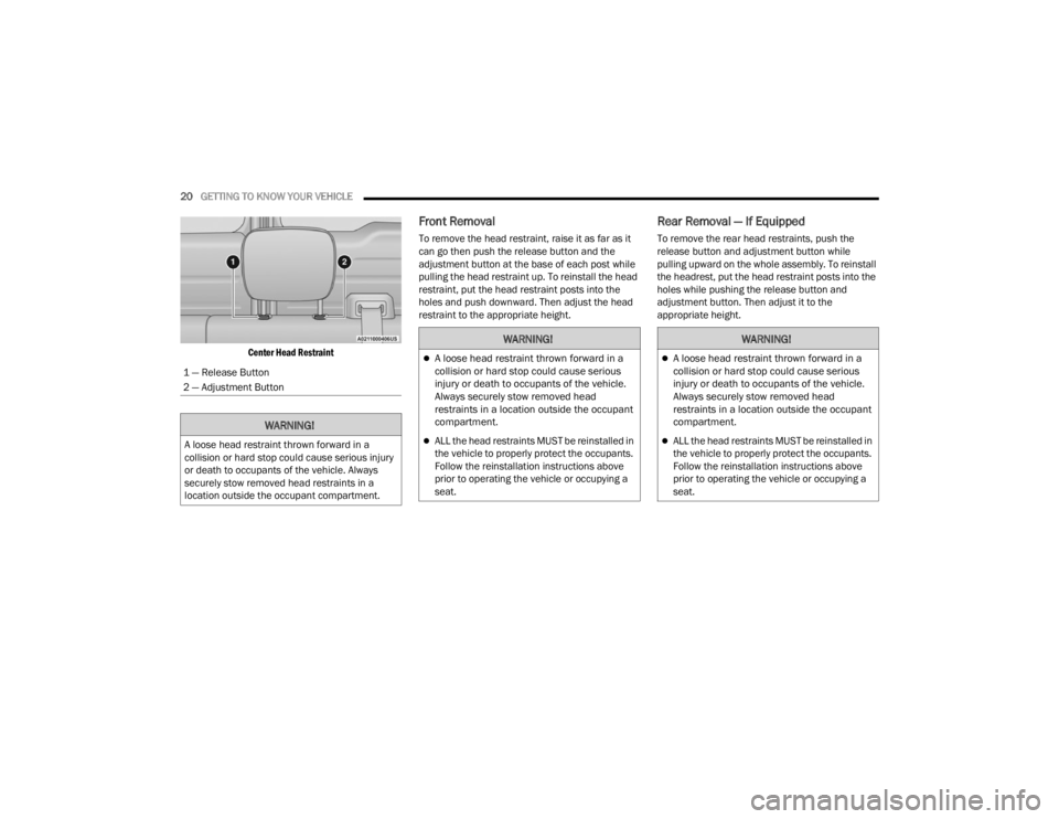
Center Head Restraint
Front Removal
To remove the head restraint, raise it as far as it
can go then push the release button and the
adjustment button at the base of each post while
pulling the head restraint up. To reinstall the head
restraint, put the head restraint posts into the
holes and push downward. Then adjust the head
restraint to the appropriate height.
Rear Removal — If Equipped
To remove the rear head restraints, push the
release button and adjustment button while
pulling upward on the whole assembly. To reinstall
the headrest, put the head restraint posts into the
holes while pushing the release button and
adjustment button. Then adjust it to the
appropriate height.
1 — Release Button
2 — Adjustment Button
WARNING!
A loose head restraint thrown forward in a
collision or hard stop could cause serious injury
or death to occupants of the vehicle. Always
securely stow removed head restraints in a
location outside the occupant compartment.
WARNING!
A loose head restraint thrown forward in a
collision or hard stop could cause serious
injury or death to occupants of the vehicle.
Always securely stow removed head
restraints in a location outside the occupant
compartment.
ALL the head restraints MUST be reinstalled in
the vehicle to properly protect the occupants.
Follow the reinstallation instructions above
prior to operating the vehicle or occupying a
seat.
22_VM_OM_EN_USC_t.book Page 20
Page 24 of 260
22GETTING TO KNOW YOUR VEHICLE
MIRRORS
INSIDE REARVIEW MIRROR
Manual Mirror — If Equipped
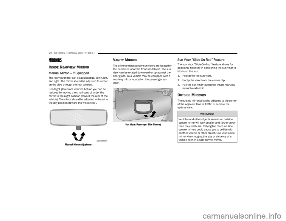
The rearview mirror can be adjusted up, down, left,
and right. The mirror should be adjusted to center
on the view through the rear window.
Headlight glare from vehicles behind you can be
reduced by moving the small control under the
mirror to the night position (toward the rear of the
vehicle). The mirror should be adjusted while set in
the day position (toward the windshield).
Manual Mirror Adjustment
VANITY MIRROR
The driver and passenger sun visors are located on
the headliner, near the front windshield. The sun
visor can be rotated downward or up against the
door glass. Your vehicle may be equipped with a
courtesy mirror located on the passenger sun
visor.
Sun Visor (Passenger Side Shown)
Sun Visor “Slide-On-Rod” Feature
The sun visor “Slide-On-Rod” feature allows for
additional flexibility in positioning the sun visor to
block out the sun.
1. Fold down the sun visor.
2. Unclip the visor from the corner clip.
3. Pull the sun visor toward the inside rearview mirror to extend it.
OUTSIDE MIRRORS
The outside mirror(s) can be adjusted to the center
of the adjacent lane of traffic to achieve the
optimal view.
WARNING!
Vehicles and other objects seen in an outside
convex mirror will look smaller and farther away
than they really are. Relying too much on side
convex mirrors could cause you to collide with
another vehicle or other object. Use your inside
mirror when judging the size or distance of a
vehicle seen in a side convex mirror.
22_VM_OM_EN_USC_t.book Page 22
Page 25 of 260
GETTING TO KNOW YOUR VEHICLE23
Outside Mirrors Folding Feature
The door mirrors are hinged to allow the mirror to
be folded forward or rearward to help avoid
damage.
Folding Mirrors
Manual Outside Mirrors — If Equipped
From the inside of the vehicle, use the control lever
to adjust the mirror.
Manual Mirror Control Lever
Power Outside Mirrors — If Equipped
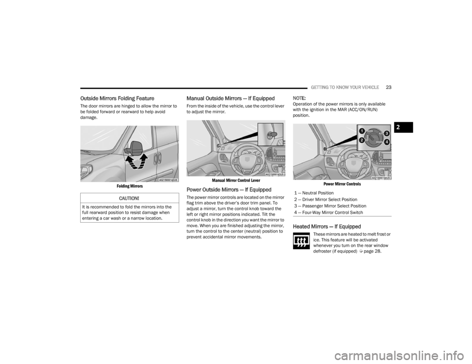
The power mirror controls are located on the mirror
flag trim above the driver’s door trim panel. To
adjust a mirror, turn the control knob toward the
left or right mirror positions indicated. Tilt the
control knob in the direction you want the mirror to
move. When you are finished adjusting the mirror,
turn the control to the center (neutral) position to
prevent accidental mirror movements.
NOTE:Operation of the power mirrors is only available
with the ignition in the MAR (ACC/ON/RUN)
position.
Power Mirror Controls
Heated Mirrors — If Equipped
These mirrors are heated to melt frost or
ice. This feature will be activated
whenever you turn on the rear window
defroster (if equipped) Ú page 28.
CAUTION!
It is recommended to fold the mirrors into the
full rearward position to resist damage when
entering a car wash or a narrow location.
1 — Neutral Position
2 — Driver Mirror Select Position
3 — Passenger Mirror Select Position
4 — Four-Way Mirror Control Switch
2
22_VM_OM_EN_USC_t.book Page 23