2022 NISSAN SENTRA warning
[x] Cancel search: warningPage 219 of 528
WARNING
Failure to follow the warnings and in-
structions for the proper use of the In-
telligent Around View Monitor system
could result in serious injury or death
• The Intelligent Around View Monitor
is a convenience feature and is not a
substitute for proper vehicle opera-
tion because it has areas where ob-
jects cannot be viewed. The four cor-
ners of the vehicle in particular, are
areas where objects do not always
appear in the bird’s-eye, front, or rear
views. Always check your surround-
ings to be sure that it is safe to move
before operating the vehicle. Always
operate the vehicle slowly.
• The driver is always responsible for
safety during parking and other
maneuvers.
CAUTION
Do not scratch the camera lens when
cleaning dirt or snow from the front of
the camera. The Intelligent Around View Monitor sys-
tem is designed as an aid to the driver in
situations such as slot parking or parallel
parking.
The monitor displays various views of the
position of the vehicle in a split screen for-
mat. Not all views are available at all times.
Available views:
• Front View
An approximately 150–degree view of the
front of the vehicle.
• Rear View An approximately 150–degree view of the
rear of the vehicle.
• Bird's-Eye View The surrounding views of the vehicle
from above.
• Front-Side View The view around and ahead of the front
passenger's side wheel.
• Full Screen Rear View (if so equipped) The view to the rear of the vehicle (which
is a little wider than the standard Rear
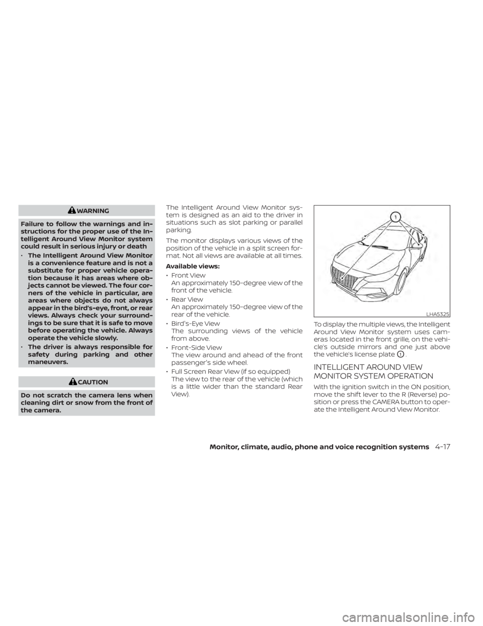
View). To display the multiple views, the Intelligent
Around View Monitor system uses cam-
eras located in the front grille, on the vehi-
cle’s outside mirrors and one just above
the vehicle’s license plate
O1.
INTELLIGENT AROUND VIEW
MONITOR SYSTEM OPERATION
With the ignition switch in the ON position,
move the shif t lever to the R (Reverse) po-
sition or press the CAMERA button to oper-
ate the Intelligent Around View Monitor.
LHA5325
Page 231 of 528
WARNING
Failure to follow the warnings and in-
structions for proper use of the Moving
Object Detection (MOD) system could
result in serious injury or death
• The MOD system is not a substitute
for proper vehicle operation and is
not designed to prevent contact with
objects surrounding the vehicle.
When maneuvering, always use the
outside mirrors and rearview mirror
and turn and check the surroundings
to ensure it is safe to maneuver.
• The system is deactivated at speeds
above 5 mph (8 km/h). It is reacti-
vated at lower speeds.
• The MOD system is not designed to
detect surrounding stationary
objects.
The MOD system can inform the driver of
moving objects near the vehicle when
backing out of garages, maneuvering in
parking lots and in other such instances.
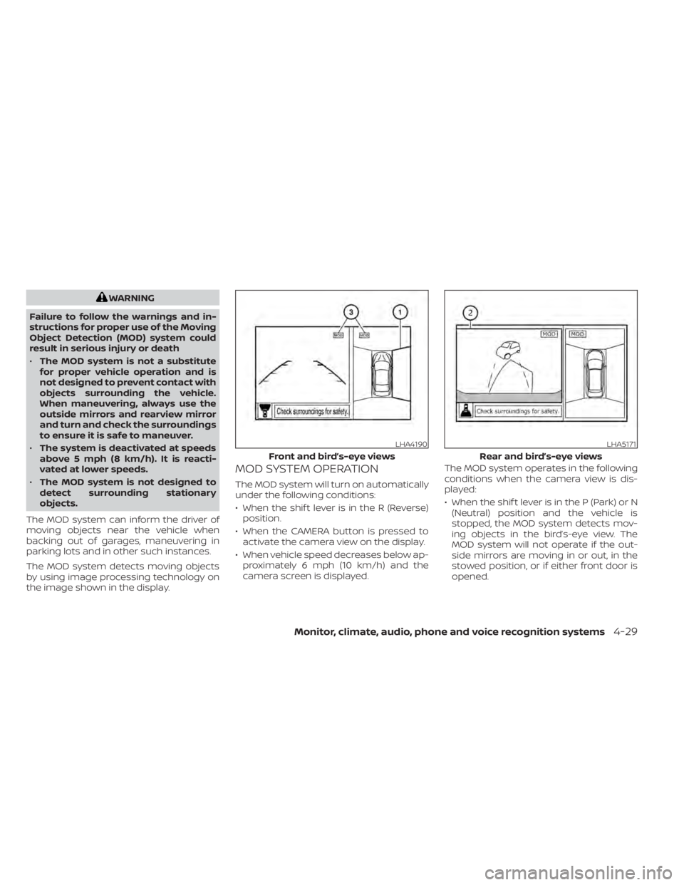
The MOD system detects moving objects
by using image processing technology on
the image shown in the display.
MOD SYSTEM OPERATION
The MOD system will turn on automatically
under the following conditions:
• When the shif t lever is in the R (Reverse) position.
• When the CAMERA button is pressed to activate the camera view on the display.
• When vehicle speed decreases below ap- proximately 6 mph (10 km/h) and the
camera screen is displayed. The MOD system operates in the following
conditions when the camera view is dis-
played:
• When the shif t lever is in the P (Park) or N
(Neutral) position and the vehicle is
stopped, the MOD system detects mov-
ing objects in the bird’s-eye view. The
MOD system will not operate if the out-
side mirrors are moving in or out, in the
stowed position, or if either front door is
opened.
LHA4190
Front and bird’s-eye views
Monitor, climate, audio, phone and voice recognition systems4-29
Page 269 of 528
When installing a CB, ham radio or car
phone in your vehicle, be sure to observe
the following precautions; otherwise, the
new equipment may adversely affect the
engine control system and other electronic
parts.CAUTION
• Keep the antenna as far away as pos-
sible from the electronic control
modules.
• Keep the antenna wire more than 8 in
(20 cm) away from the electronic
control system harnesses. Do not
route the antenna wire next to any
harness.
• Adjust the antenna standing-wave
ratio as recommended by the
manufacturer.
• Connect the ground wire from the CB
radio chassis to the body.
• For additional information, it is rec-
ommended that you visit a NISSAN
dealer for this service.WARNING
• Use a phone af ter stopping your ve-
hicle in a safe location. If you have to
use a phone while driving, exercise
extreme caution at all times so full
attention may be given to vehicle
operation.
• If you are unable to devote full atten-
tion to vehicle operation while talk-
ing on the phone, pull off the road to
a safe location and stop your vehicle.
CAUTION
To avoid discharging the vehicle bat-
tery, use a phone af ter starting the en-
gine.
CAR PHONE OR CB RADIO BLUETOOTH® HANDS-FREE PHONE
SYSTEM
Monitor, climate, audio, phone and voice recognition systems4-67
Page 288 of 528
System maintenance.......................5-47
RearCrossTrafficAlert(RCTA) .................. 5-48
RCTA system operation .....................5-48
How to enable/disable the RCTA
system ...................................... 5-51
RCTA system limitations .....................5-53
System temporarily unavailable .............5-55
System maintenance .......................5-57
Cruise control (if so equipped) ..................5-58
Precautions on cruise control ...............5-58
Cruise control operations ...................5-58
Intelligent Cruise Control (ICC) (if so equipped) . . 5-59 ICC system operation ....................... 5-61
The ICC switch .............................. 5-62
ICC system limitations ......................5-68
System temporarily unavailable .............5-71
System maintenance .......................5-73
Rear Automatic Braking (RAB) ..................5-74
RAB system operation .......................5-75
Turning the RAB system on/off ..............5-77
RAB system limitations ......................5-77
System malfunction ......................... 5-80
System maintenance .......................5-80
Automatic Emergency Braking (AEB) with
Pedestrian Detection ........................... 5-81AEB with Pedestrian Detection system
operation
................................... 5-82
Turning the AEB with Pedestrian
Detection system ON/OFF ..................5-85
AEB with Pedestrian Detection system
limitations .................................. 5-86
System temporarily unavailable .............5-88
System malfunction ......................... 5-90
System maintenance .......................5-90
Intelligent Forward Collision Warning (I-FCW) . . . 5-92 I-FCW system operation .....................5-95
Turning the I-FCW system on/off ............5-96
I-FCW system limitations ....................5-97
System temporarily unavailable ............5-102
System malfunction ........................ 5-104
System maintenance ......................5-104
Intelligent
Driver Alertness (I-DA) ...............5-105
Intelligent Driver Alertness system
operation .................................. 5-106
How to enable/disable the Intelligent
Driver Alertness (I-DA) system ..............5-107
Intelligent Driver Alertness (I-DA)
system limitations ......................... 5-108
Break-in schedule ............................. 5-109
Fuel efficient driving tips .......................5-110
Page 290 of 528
WARNING
• Do not leave children or adults who
would normally require the assis-
tance of others alone in your vehicle.
Pets should also not be lef t alone.
They could accidentally injure them-
selves or others through inadvertent
operation of the vehicle. Also, on hot,
sunny days, temperatures in a closed
vehicle could quickly become high
enough to cause severe or possibly
fatal injuries to people or animals.
• Closely supervise children when they
are around cars to prevent them
from playing and becoming locked in
the trunk where they could be seri-
ously injured. Keep the car locked,
with the rear seatback and trunk lid
securely latched when not in use, and
prevent children's access to car keys.
EXHAUST GAS (carbon monoxide)
air recirculation but-
ton to off and the fan control dial
to high to circulate the air.
• If electrical wiring or other cable con-
nections must pass to a trailer
through the seal on the trunk lid or
the body, follow the manufacturer's
recommendation to prevent carbon
monoxide entry into the vehicle. •
The exhaust system and body should
be inspected by a qualified mechanic
whenever:
a. The vehicle is raised for service.
b. You suspect that exhaust fumes are entering into the passenger
compartment.
c. You notice a change in the sound of the exhaust system.
d. You have had an accident involv- ing damage to the exhaust sys-
tem, underbody, or rear of the
vehicle.
THREE-WAY CATALYST
The three-way catalyst is an emission con-
trol device installed in the exhaust system.
Exhaust gases in the three-way catalyst
are burned at high temperatures to help
reduce pollutants.
Page 292 of 528
Additional information:
• When replacing a wheel without theTPMS such as the spare tire, the TPMS
does not monitor the tire pressure of the
spare tire.
• The TPMS will activate only when the ve- hicle is driven at speeds above 16 mph (25
km/h). Also, this system may not detect a
sudden drop in tire pressure (for example,
a flat tire while driving).
• The low tire pressure warning light does not automatically turn off when the tire
pressure of all your tires is adjusted. Af ter
the tires are inflated to the recom-
mended pressure, the vehicle must be
driven at speeds above 16 mph (25 km/h)
to activate the TPMS and turn off the low
tire pressure warning light. Use a tire
pressure gauge to check the tire pres-
sure. • The “CHECK TIRE PRES” (TypeA-ifso
equipped) or the “Tire Pressure Low - Add
Air”(TypeB-ifsoequipped) warning mes-
sage is displayed in the odometer when
the low tire pressure warning light is illu-
minated and low tire pressure is de-
tected. The “CHECK TIRE PRES” (Typ eA-if
so equipped) or the “Tire Pressure Low -
AddAir”(TypeB-ifsoequipped) warning
message turns off when the low tire pres-
sure warning light turns off. The low tire
pressure warning light remains illumi-
nated until the tires are inflated to the
recommended COLD tire pressure. The
“CHECK TIRE PRES” (TypeA-ifso
equipped) or the “Tire Pressure Low - Add
Air”(TypeB-ifsoequipped) warning mes-
sage is displayed each time the ignition
switch is placed in the ON position as
long as the low tire pressure warning light
remains illuminated.
• The “CHECK TIRE PRES” (TypeA-ifso equipped) or the “Tire Pressure Low - Add
Air”(TypeB-ifsoequipped) warning is not
displayed if the low tire pressure warning
light illuminates to indicate a TPMS mal-
function. • Tire pressure rises and falls depending on
the heat caused by the vehicle’s opera-
tion and the outside temperature. Do not
reduce the tire pressure af ter driving be-
cause the tire pressure rises af ter driving.
Low outside temperature can lower the
temperature of the air inside the tire
which can cause a lower tire inflation
pressure. This may cause the low tire
pressure warning light to illuminate. If the
warning light illuminates, check the tire
pressure for all four tires.
• The Tire and Loading Information label is located in the driver's door opening.
For additional information, refer to “Check
tire pressure warning message” or “Low tire
pressure warning light” in the “Instruments
and controls” section and “Tire Pressure
Monitoring System (TPMS)” in the “In case of
emergency” section of this manual.
Page 293 of 528
•If the low tire pressure warning light
illuminates while driving, avoid sud-
den steering maneuvers or abrupt
braking, reduce vehicle speed, pull
off the road to a safe location and
stop the vehicle as soon as possible.
Driving with under-inflated tires may
permanently damage the tires and
increase the likelihood of tire failure.
Serious vehicle damage could occur
and may lead to an accident and
could result in serious personal in-
jury. Check the tire pressure for all
four tires. Adjust the tire pressure to
the recommended COLD tire pres-
sure shown on the Tire and Loading
Information label to turn the low tire
pressure warning light off. If you have
a flat tire, replace it with a spare tire
as soon as possible. (For additional
information on changing a flat tire,
refer to “Flat tire” in the “In case of
emergency ” section of this manual.) •
When replacing a wheel without the
TPMS such as the spare tire, when a
spare tire is mounted or a wheel is
replaced, the TPMS will not function
and the low tire pressure warning
light will flash for approximately 1
minute. The light will remain on af ter
1 minute. Have your tires replaced
and/or TPMS reset as soon as pos-
sible. It is recommended that you
visit a NISSAN dealer for this service.
• Replacing tires with those not origi-
nally specified by NISSAN could af-
fect the proper operation of the
TPMS.
• Do not inject any tire liquid or aerosol
tire sealant into the tires, as this may
cause a malfunction of the tire pres-
sure sensors.
CAUTION
Do not place metalized film or any
metal parts (antenna, etc.) on the win-
dows. This may cause poor reception of
the signals from the tire pressure sen-
sors, and the TPMS will not function
properly. Some devices and transmitters may tem-
porarily interfere with the operation of the
TPMS and cause the low tire pressure
warning light to illuminate.
Some examples are:
• Facilities or electric devices using similar
radio frequencies are near the vehicle.
• If a transmitter set to similar frequencies is being used in or near the vehicle.
• If a computer (or similar equipment) or a DC/AC converter is being used in or near
the vehicle.
The low tire pressure warning light may
illuminate in the following cases:
• If the vehicle is equipped with a wheel and tire without TPMS.
• If the TPMS has been replaced and the ID has not been registered.
• If the wheel is not originally specified by NISSAN.
FCC Notice:
For USA:
This device complies with Part 15 of the
FCC Rules. Operation is subject to the fol-
lowing two conditions: (1) This device
may not cause harmful interference, and
Starting and driving5-7
Page 297 of 528
WARNING
Do not operate the push-button igni-
tion switch while driving the vehicle ex-
cept in an emergency. (The engine will
stop when the ignition switch is pushed
three consecutive times in quick suc-
cession or the ignition switch is pushed
and held for more than 2 seconds.) If
the engine stops while the vehicle is
being driven, this could lead to a crash
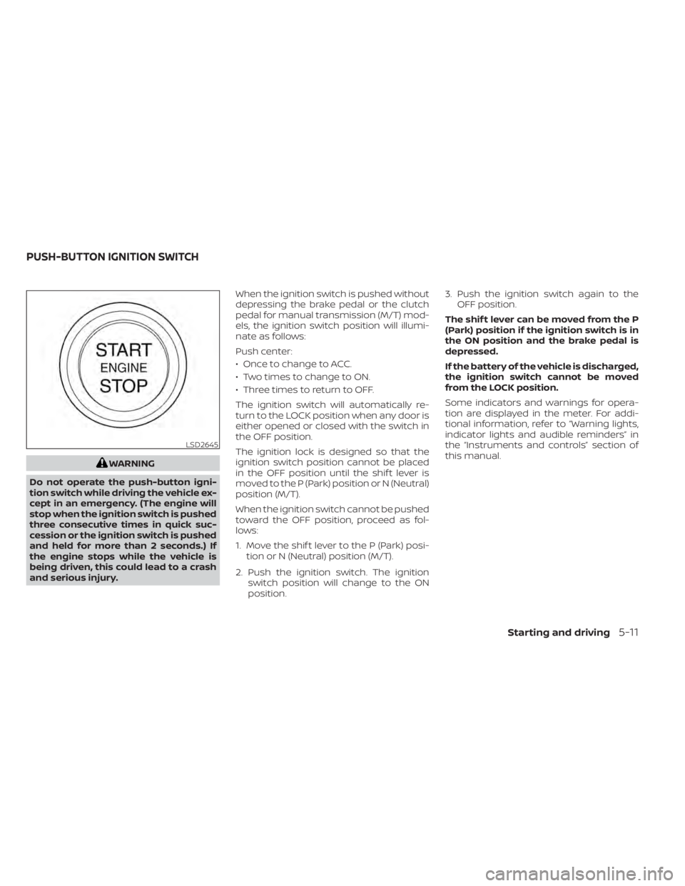
and serious injury. When the ignition switch is pushed without
depressing the brake pedal or the clutch
pedal for manual transmission (M/T) mod-
els, the ignition switch position will illumi-
nate as follows:
Push center:
• Once to change to ACC.
• Two times to change to ON.
• Three times to return to OFF.
The ignition switch will automatically re-
turn to the LOCK position when any door is
either opened or closed with the switch in
the OFF position.
The ignition lock is designed so that the
ignition switch position cannot be placed
in the OFF position until the shif t lever is
moved to the P (Park) position or N (Neutral)
position (M/T).
When the ignition switch cannot be pushed
toward the OFF position, proceed as fol-
lows:
1. Move the shif t lever to the P (Park) posi-
tion or N (Neutral) position (M/T).
2. Push the ignition switch. The ignition switch position will change to the ON
position. 3. Push the ignition switch again to the
OFF position.
The shif t lever can be moved from the P
(Park) position if the ignition switch is in
the ON position and the brake pedal is
depressed.
If the battery of the vehicle is discharged,
the ignition switch cannot be moved
from the LOCK position.
Some indicators and warnings for opera-
tion are displayed in the meter. For addi-
tional information, refer to “Warning lights,
indicator lights and audible reminders” in
the “Instruments and controls” section of
this manual.
LSD2645
PUSH-BUTTON IGNITION SWITCH
Starting and driving5-11