2022 HYUNDAI KONA EV Display speed
[x] Cancel search: Display speedPage 51 of 548
Foreword / Electric Vehicle System Overview
1-46
Virtual Engine Sound System
The Virtual Engine Sound System
generates engine sound for pedestrians
to hear vehicle sound because there is
no sound while the Electric Vehicle (EV)
is operating. • If the vehicle is in the ready (
)
mode and the gear is not in P (Park),
the VESS will be operated.
• When the gear is shifted to R
(Reverse), an additional warning
sound will be heard.
CAUTION
• The vehicle is much quieter while
driving than a conventional gasoline-
powered vehicle. Be aware of your
surroundings and always drive safely.
• After you park the vehicle or while
you are waiting at a traffic light,
check whether there are children or
obstacles around the vehicle.
• Check if there is something behind
the vehicle when driving in reverse.
Pedestrians may not hear the sound
of the vehicle.
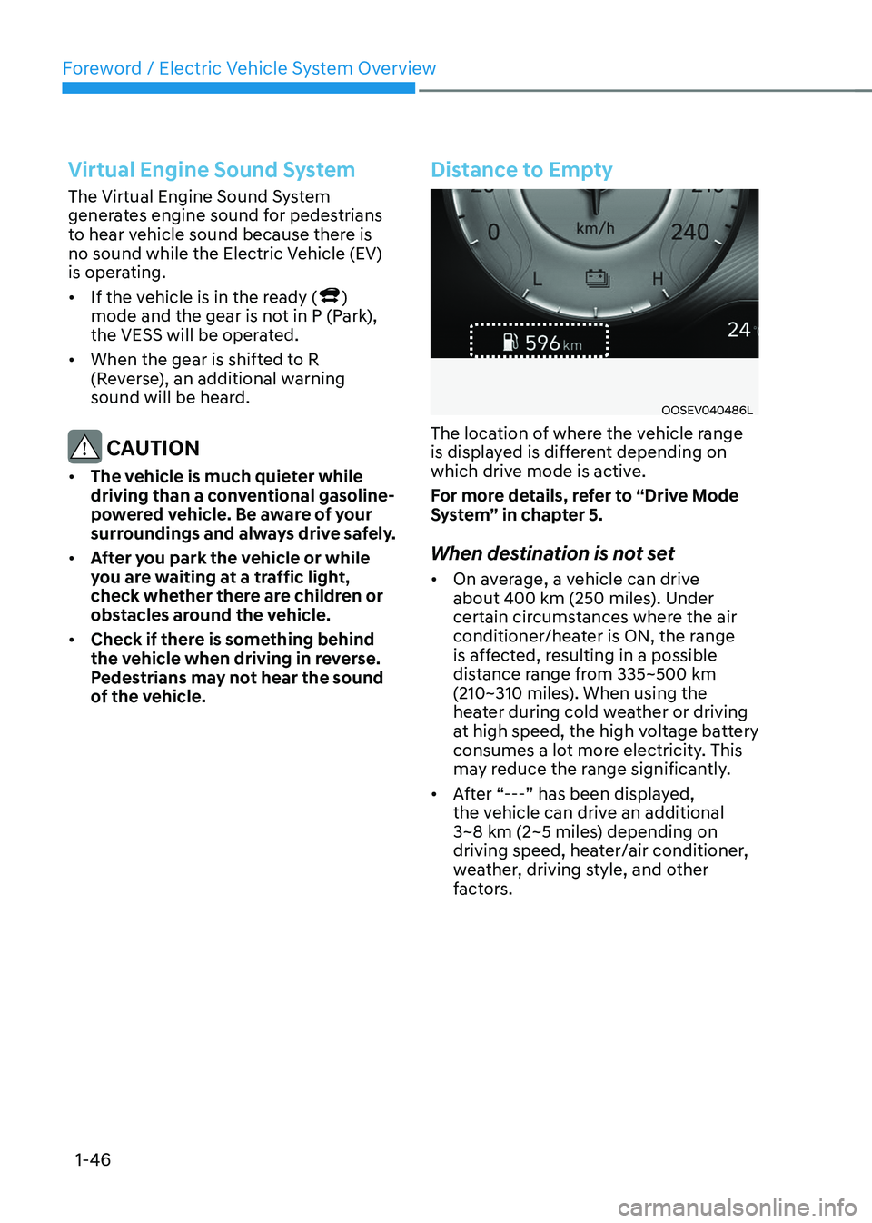
Distance to Empty
OOSEV040486L
The location of where the vehicle range
is displayed is different depending on
which drive mode is active.
For more details, refer to “Drive Mode
System” in chapter 5.
When destination is not set • On average, a vehicle can drive
about 400 km (250 miles). Under
certain circumstances where the air
conditioner/heater is ON, the range
is affected, resulting in a possible
distance range from 335~500 km
(210~310 miles). When using the
heater during cold weather or driving
at high speed, the high voltage battery
consumes a lot more electricity. This
may reduce the range significantly.
• After “---” has been displayed,
the vehicle can drive an additional
3~8 km (2~5 miles) depending on
driving speed, heater/air conditioner,
weather, driving style, and other
factors.
Page 52 of 548

01
1-47
•
The range that is displayed on the
instrument cluster after completing
a recharge may vary significantly
depending on previous driving
patterns.
When the previous driving patterns
include aggressive or high speed
driving (e.g. predominantly highway
miles, etc.), the estimated range on
the next full charge will be lower than normal.
When the previous driving patterns
are predominantly mild or economical
(e.g. city driving), the estimated
range on the next full charge will be
increased.
• Calculated range may depend on
many factors such as the charge
amount of the high voltage battery,
weather, temperature, durability of
the battery, geographical features,
and driving style.
• Natural degradation may occur with
the high voltage battery depending
on the number of years the vehicle
is used. This may reduce the vehicle
range.
Navigation - When a Destination is
Set
When a destination is set using the
vehicle navigation system (if equipped),
the vehicle range may change. The
vehicle range is recalculated using the
destination route information. While
driving, the range may vary based on
traffic conditions, driving pattern and
vehicle settings, etc.
Tips for Improving Range When
Using the Climate Control
System
• Operating the climate control system
consumes electrical energy from
the EV battery. Continuous use may
reduce the vehicle range.
When using the climate control
system, it is recommended to set
the control to 22°C (72°F) AUTO. The
climate control system has been
optimized to operate at this setting for
maximum comfort and efficiency.
• When possible, use the DRIVER ONLY
feature on the climate control system.
This will discontinue airflow to the
passenger side and reduces climate
control power consumption.
Tips for Improving Range While Driving
• Depress and hold the accelerator
pedal to maintain speed and drive
economically.
• Gradually depress and release the
accelerator pedal when accelerating
or decelerating.
• Always maintain specified tire
pressures.
• Do not use unnecessary electrical
components while driving.
• Do not load unnecessary items in the
vehicle.
• Do not mount parts that may increase
air resistance.
Page 127 of 548
Safety system
3-48
SRS warning light
The SRS (Supplemental Restraint System)
air bag warning light on the instrument
panel displays the air bag symbol
depicted in the illustration. The system
checks the air bag electrical system for
malfunctions. The light indicates that
there is a potential problem with your
air bag system, which could include
your side and/or curtain air bags used
for rollover protection (if equipped with
rollover sensor).
WARNING
If your SRS malfunctions, the air bag
may not inflate properly during an
accident increasing the risk of serious
injury or death.
If any of the following conditions occur,
your SRS is malfunctioning: • The light does not turn on for
approximately three to six seconds
when the Engine Start/Stop button is in the ON position.
• The light stays on after illuminating
for approximately three to six
seconds.
• The light comes on while the vehicle
is in motion.
• The light blinks when the engine is running.
We recommend that an authorized
HYUNDAI dealer inspect the SRS
as soon as possible if any of these
conditions occur. During a moderate to severe frontal
collision, sensors will detect the
vehicle’s rapid deceleration. If the rate of
deceleration is high enough, the control
unit will inflate the front air bags, at the
time and with the force needed.
The front air bags help protect the driver
and front passenger by responding to
frontal impacts in which seat belts alone
cannot provide adequate restraint. When
needed, the side air bags help provide
protection in the event of a side impact
or rollover by supporting the side upper
body area. •
Air bags are activated (able to inflate if
necessary) only when the START/STOP
button is in the ON position.
• Air bags inflate in the event of certain
frontal or side collisions to help
protect the occupants from serious
physical injury.
• There is no single speed at which the
air bags will inflate. Generally, air bags
are designed to inflate based upon the
severity of a collision and its direction.
These two factors determine whether
the sensors produce an electronic
deployment/inflation signal.
• The front air bags will completely
inflate and deflate in an instant. It is
virtually impossible for you to see the
air bags inflate during an accident. It is
much more likely that you will simply
see the deflated air bags hanging out
of their storage compartments after the collision.
Page 144 of 548
4
Instrument cluster ............................................................................................ 4-2
Instrument cluster control ........................................................................................... 4-3
Instrument panel illumination ................................................................................... 4-3
Gauges and meters ...................................................................................................... 4-3
Speedometer ............................................................................................................. 4-3
Power/Charge gauge................................................................................................. 4-3
State of Charge (SOC) gauge for high voltage battery ..........................................4-4
Outside Temperature Gauge .................................................................................... 4-4
Odometer ................................................................................................................... 4-5
Distance to empty ..................................................................................................... 4-5
Reduction gear shift indicator ................................................................................. 4-6
Regenerative braking level indicator ....................................................................... 4-6
Warning and indicator lights ....................................................................................... 4 -7
LCD display messages ..................................................................................... 4-17
LCD display ....................................................................................................... 4-27
LCD display control .................................................................................................... 4-27
View modes ................................................................................................................ 4-28
Trip computer mode ................................................................................................ 4-29
Turn By Turn (TBT) mode ......................................................................................... 4-29
Driving assist mode ................................................................................................. 4-29
Master warning group ............................................................................................ 4-30
User settings mode .................................................................................................... 4-31
Trip computer .................................................................................................. 4-39
Trip modes ................................................................................................................ 4-39
Drive Info ................................................................................................................. 4-40
After Recharging ..................................................................................................... 4-40
Accumulated info ..................................................................................................... 4-41
Energy flow .............................................................................................................. 4-41
Digital speedometer ................................................................................................ 4-41
4. Instrument cluster
Page 145 of 548
4-2
Instrument cluster
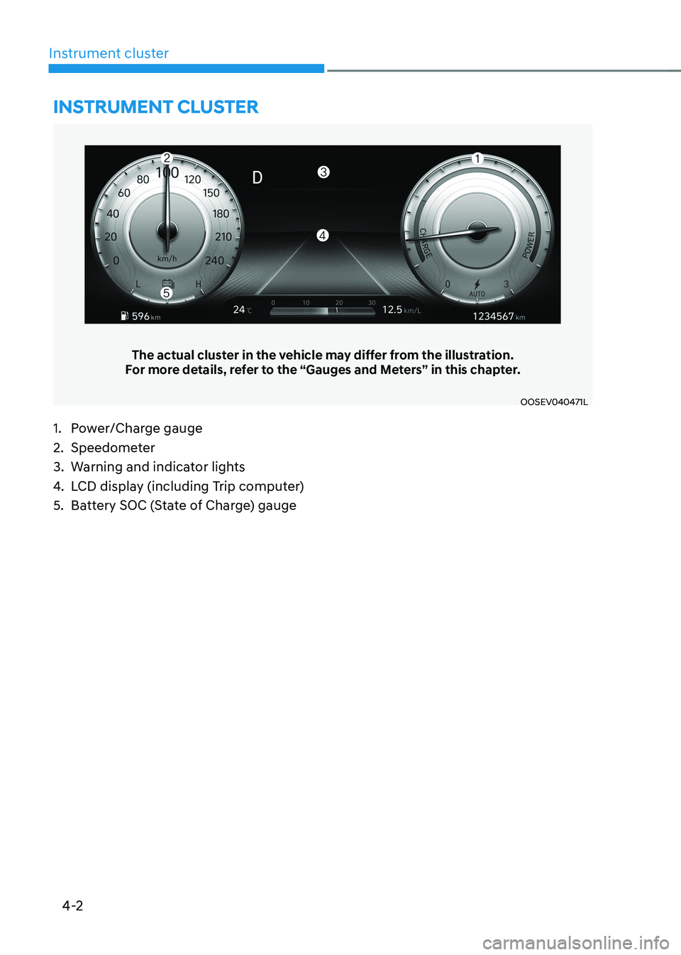
The actual cluster in the vehicle may differ from the illustration.
For more details, refer to the “Gauges and Meters” in this chapter.
OOSEV040471L
Instrument cluster
1. Power/Charge gauge
2. Speedometer
3. Warning and indicator lights
4. LCD display (including Trip computer)
5. Battery SOC (State of Charge) gauge
Page 146 of 548

04
4-3
Instrument cluster control
Instrument panel illumination
OOSEV040056L
When the vehicle’s position lights or
headlamps are on, press the illumination
control button to adjust the brightness of
the instrument panel illumination.
When pressing the illumination control
button, the interior switch illumination
intensity is also adjusted.
WARNING
Never adjust the instrument cluster
while driving. This could result in loss
of control and lead to an accident that
may cause death, serious injury, or
vehicle damage.
OCN7040019L
• The brightness of the instrument
panel illumination is displayed.
• If the brightness reaches the
maximum or minimum level, an alarm will sound.
Gauges and meters
Speedometer
OOSEV040472L
The speedometer indicates the speed of
the vehicle and is calibrated in kilometers
per hour (km/h).
Power/Charge gauge
OOSEV040474L
The Power/Charge gauge shows the
energy consumption rate of the vehicle
and the charge/discharge status of the
regenerative brakes. • POWER :
It shows the energy consumption rate
of the vehicle when driving uphill or
accelerating. The more electric energy is
used, the higher the gauge level. • CHARGE :
It shows the charging status of the
battery when it is being charged by the
regenerative brakes (decelerating or
driving on a downhill road). The more
electric energy is charged, the lower the
gauge level.
Page 147 of 548
Instrument cluster
4-4
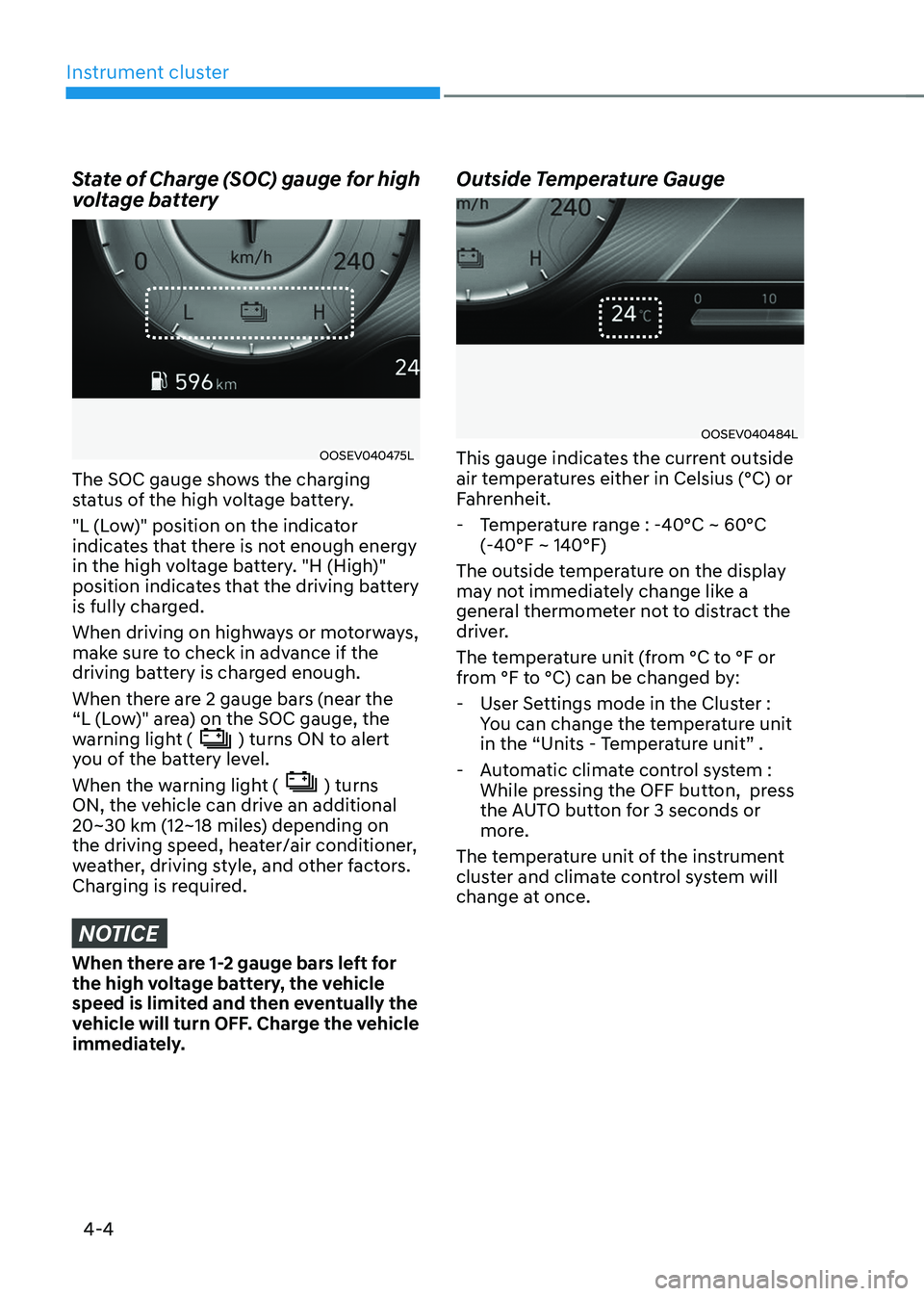
State of Charge (SOC) gauge for high
voltage battery
OOSEV040475L
The SOC gauge shows the charging
status of the high voltage battery.
"L (Low)" position on the indicator
indicates that there is not enough energy
in the high voltage battery. "H (High)"
position indicates that the driving battery
is fully charged.
When driving on highways or motorways,
make sure to check in advance if the
driving battery is charged enough.
When there are 2 gauge bars (near the
“L (Low)" area) on the SOC gauge, the
warning light (
) turns ON to alert
you of the battery level.
When the warning light (
) turns
ON, the vehicle can drive an additional
20~30 km (12~18 miles) depending on
the driving speed, heater/air conditioner,
weather, driving style, and other factors.
Charging is required.
NOTICE
When there are 1-2 gauge bars left for
the high voltage battery, the vehicle
speed is limited and then eventually the
vehicle will turn OFF. Charge the vehicle
immediately. Outside Temperature Gauge
OOSEV040484L
This gauge indicates the current outside
air temperatures either in Celsius (°C) or
Fahrenheit.
- Temperature range : -40°C ~ 60°C (-40°F ~ 140°F)
The outside temperature on the display
may not immediately change like a
general thermometer not to distract the
driver.
The temperature unit (from °C to °F or
from °F to °C) can be changed by: - User Settings mode in the Cluster : You can change the temperature unit
in the “Units - Temperature unit” .
- Automatic climate control system : While pressing the OFF button, press
the AUTO button for 3 seconds or
more.
The temperature unit of the instrument
cluster and climate control system will
change at once.
Page 155 of 548

Instrument cluster
4-12
Electric Power Steering (EPS)
Warning Light
This warning light illuminates:
•
When the START/STOP button is in the ON position.
- It illuminates for approximately 3 seconds and then goes off.
• When there is a malfunction with the
Electric Power Steering System.
In this case, we recommend that
you have the vehicle inspected by an
authorized HYUNDAI dealer.
Charging System Warning
Light (for 12-volt battery)
This warning light illuminates:
• When the 12-volt battery level is low
or a failure occurs on the charging
system such as LDC.
• If the warning light turns on while
driving, move the vehicle to a safe
location, turn off and turn on the
vehicle again, and check if the
warning light turns off. If the warning
light remains on, we recommend that
you have the vehicle inspected by an
authorized HYUNDAI dealer.
• Even if the warning light turns off, we
recommend that you have the vehicle
inspected by an authorized HYUNDAI
dealer.
If you drive the vehicle while the
warning light is on, vehicle speed may
be limited and the 12-volt battery may
be discharged.
à LDC : Low voltage DC-DC Converter. Master Warning Light
This indicator light illuminates:
•
When there is a malfunction in the
below systems.
- Forward Collision-Avoidance Assist malfunction (if equipped)
- Forward Collision-Avoidance Assist radar blocked (if equipped)
- Blind-Spot Collision Warning malfunction (if equipped)
- Blind-Spot Collision Warning radar blocked (if equipped)
- LED headlamp malfunction (if equipped)
- High Beam Assist malfunction (if equipped)
- Smart Cruise Control with Stop & Go malfunction (if equipped)
- Smart Cruise Control with Stop & Go radar blocked (if equipped)
- Tire Pressure Monitoring System (TPMS) malfunction
To identify the details of the warning,
look at the LCD display.