2022 HYUNDAI KONA EV change time
[x] Cancel search: change timePage 182 of 548
04
4-39
trIp computer
The trip computer is a microcomputer-
controlled driver information system that
displays information related to driving.
Information
Some driving information stored in the
trip computer resets if the battery is disconnected.
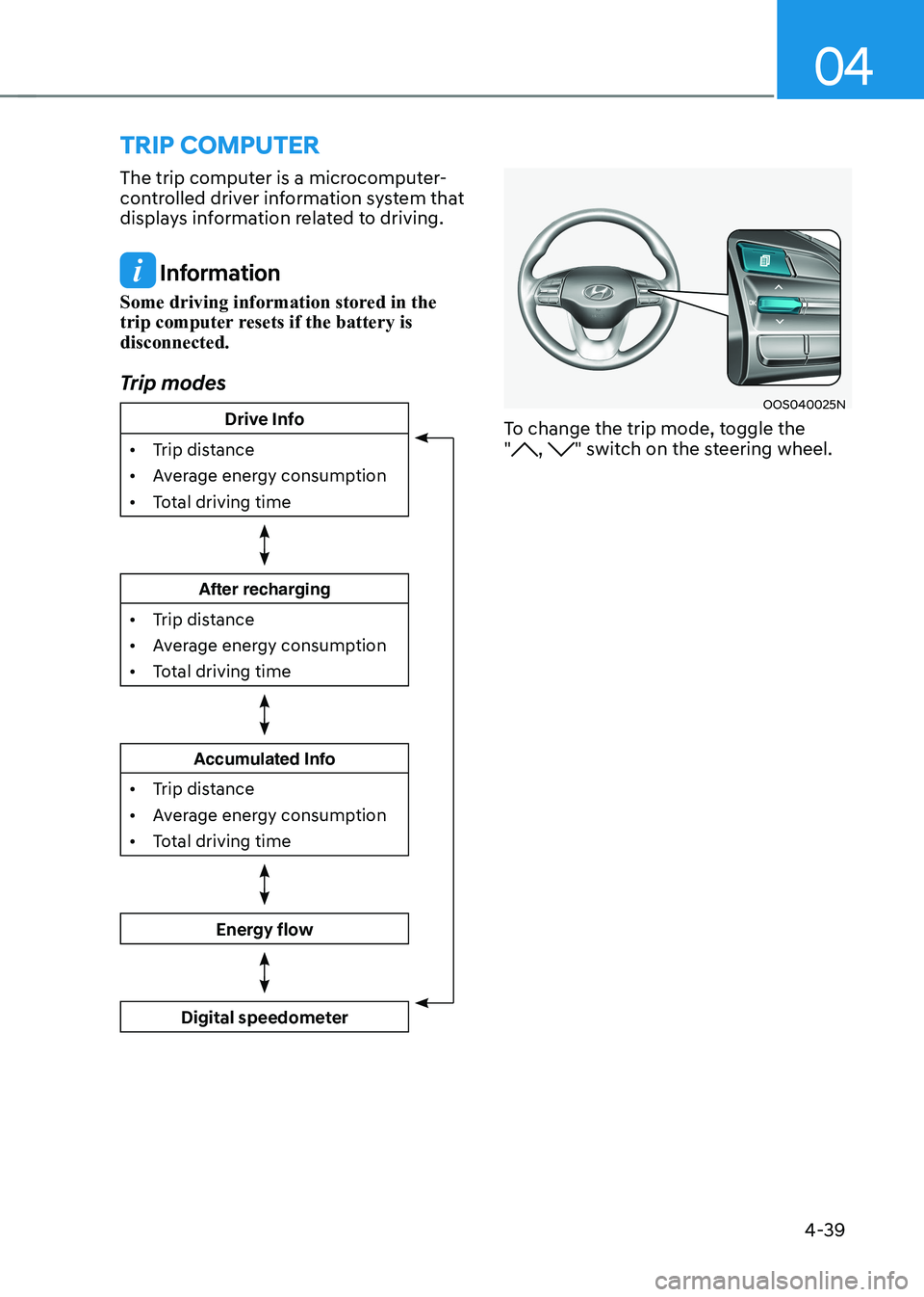
Trip modes
Drive Info
• Trip distance
• Average energy consumption
• Total driving time
After recharging
• Trip distance
• Average energy consumption
• Total driving time
Accumulated Info
• Trip distance
• Average energy consumption
• Total driving time
Energy flow
Digital speedometer
OOS040025N
To change the trip mode, toggle the "
, " switch on the steering wheel.
Page 200 of 548
Convenient features
5-16
steering wheel
Electric power steering (EPS)
The system assists you with steering
the vehicle. If the vehicle is off or if
the power steering system becomes
inoperative, the vehicle may still be
steered, but it will require increased
steering effort.
Also, the steering effort becomes heavier
as the vehicle’s speed increases and
becomes lighter as the vehicle’s speed
decreases for better control of the
steering wheel.
Should you notice any change in the
effort required to steer during normal
vehicle operation, we recommend that
the system be checked by an authorized
HYUNDAI dealer.
NOTICE
• If the Electric Power Steering System
does not operate normally, the
warning light (
) will illuminate
or blink on the instrument cluster.
The steering wheel may become
difficult to control or operate. We
recommend to contact an authorized
HYUNDAI dealer to have the system
checked as soon as possible.
• When abnormality is detected in
the electric power steering system,
to prevent a deadly accident, the
steering assist function will stop. At
this time, the warning light turns on
or blinks on the cluster. The steering
wheel may become difficult to
control or operate. Have your vehicle
checked immediately, after moving
the vehicle to a safe zone.
Information
The following symptoms may occur during normal vehicle operation: • The steering effort may be high
immediately after placing the START/
STOP button in the ON position. This happens as the system performs
the EPS system diagnostics. When
the diagnostics are completed, the
steering wheel will return to its normal condition.
• When the battery voltage is low, you
might have to put more steering effort.
However, it is a temporary condition so
that it will return to normal condition
after charging the battery.
• A click noise may be heard from the
EPS relay after the START/STOP
button is placed in the ON or OFF position.
• Motor noise may be heard when the
vehicle is at a stop or at a low driving speed.
• When you operate the steering wheel
in low temperatures, abnormal noise
may occur. If the temperature rises, the
noise will disappear. This is a normal condition.
• When the vehicle is stationary, if you turn the steering wheel all the way
to the left or right continuously, the
steering wheel effort increases. This
is not a system malfunction. As time passes, the steering wheel effort will
return to its normal condition.
Page 201 of 548
05
5-17
Tilt steering/Telescopic steering
WARNING
Never adjust the steering wheel while
driving. You may lose steering control
and cause severe personal injury, death
or accidents.
Information
After adjustment, sometimes the lock-
release lever may not lock the steering wheel.
It is not a malfunction. This occurs when
two gears are not engaged correctly. In this case, adjust the steering wheel again and then lock the steering wheel.OOS047006
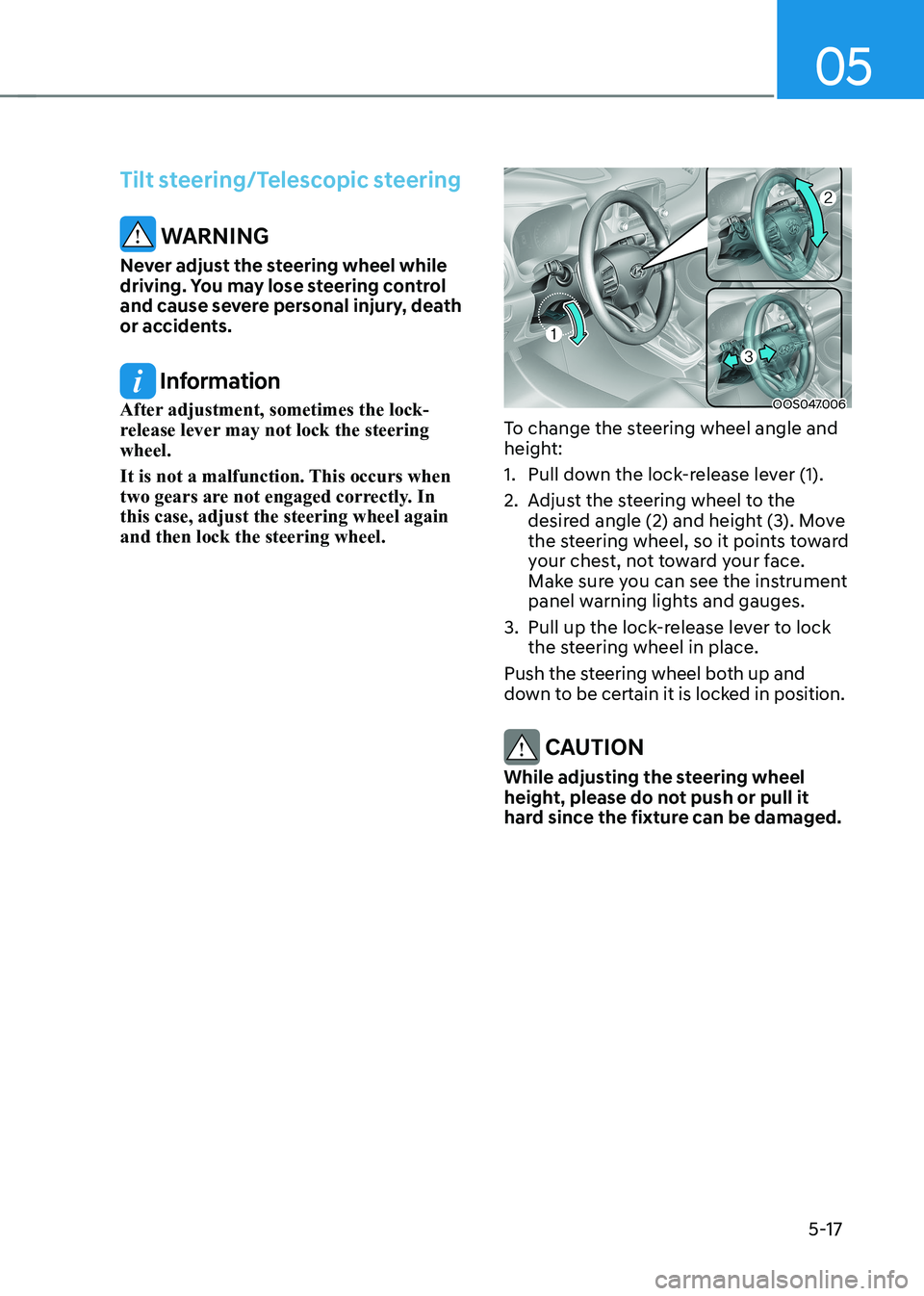
To change the steering wheel angle and
height:
1. Pull down the lock-release lever (1).
2. Adjust the steering wheel to the desired angle (2) and height (3). Move
the steering wheel, so it points toward
your chest, not toward your face.
Make sure you can see the instrument
panel warning lights and gauges.
3. Pull up the lock-release lever to lock the steering wheel in place.
Push the steering wheel both up and
down to be certain it is locked in position.
CAUTION
While adjusting the steering wheel
height, please do not push or pull it
hard since the fixture can be damaged.
Page 209 of 548
05
5-25
4) Canadian Programming
Canadian radio-frequency laws require
transmitter remote signals to "time-
out" (or quit) after a couple seconds of
transmission, which may not be long
enough for HomeLink to pick up the signal
during programming.
If you live in Canada or you are having
difficulties programming a gate operator
or garage door opener by using the
programming procedures, replace
"Programming a New HomeLink Button"
step 3 with the following:
While the HomeLink indicator light (7) is
flashing orange, press and release ("cycle")
your device's handheld remote every two
seconds until the HomeLink indicator light
(7) changes from orange to green. You may
now release the hand-held remote button.
Then proceed with "Programming a New
HomeLink Button" step 4.
2. Operating HomeLink
®
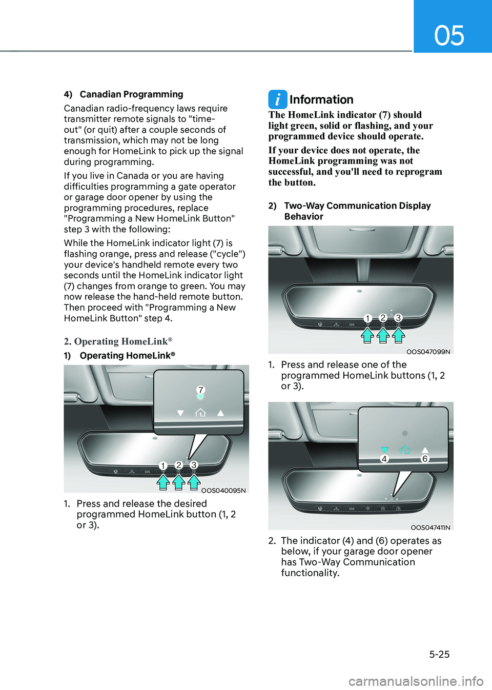
1) Operating HomeLink®
OOS040095N
1. Press and release the desired programmed HomeLink button (1, 2
or 3).
Information
The HomeLink indicator (7) should
light green, solid or flashing, and your
programmed device should operate.
If your device does not operate, the
HomeLink programming was not
successful, and you'll need to reprogram the button.
2) Two-Way Communication Display Behavior
OOS047099N
1. Press and release one of the programmed HomeLink buttons (1, 2
or 3).
OOS047411N
2. The indicator (4) and (6) operates as below, if your garage door opener
has Two-Way Communication
functionality.
Page 234 of 548
Convenient features
5-50
Turn signals and lane change signals
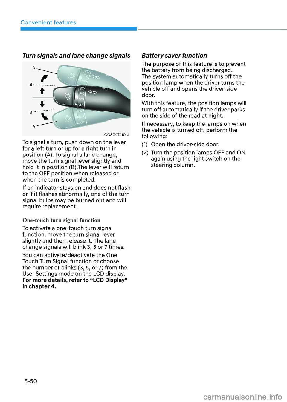
OOS047410N
To signal a turn, push down on the lever
for a left turn or up for a right turn in
position (A). To signal a lane change,
move the turn signal lever slightly and
hold it in position (B).The lever will return
to the OFF position when released or
when the turn is completed.
If an indicator stays on and does not flash
or if it flashes abnormally, one of the turn
signal bulbs may be burned out and will
require replacement.
One-touch turn signal function
To activate a one-touch turn signal
function, move the turn signal lever
slightly and then release it. The lane change signals will blink 3, 5 or 7 times.
You can activate/deactivate the One
Touch Turn Signal function or choose
the number of blinks (3, 5, or 7) from the
User Settings mode on the LCD display.
For more details, refer to “LCD Display”
in chapter 4. Battery saver function
The purpose of this feature is to prevent
the battery from being discharged.
The system automatically turns off the
position lamp when the driver turns the
vehicle off and opens the driver-side
door.
With this feature, the position lamps will
turn off automatically if the driver parks
on the side of the road at night.
If necessary, to keep the lamps on when
the vehicle is turned off, perform the
following:
(1) Open the driver-side door.
(2) Turn the position lamps OFF and ON
again using the light switch on the
steering column.
Page 241 of 548
05
5-57
Limitations of High Beam Assist
High Beam Assist may not work properly
in the following situations: •
Light from a vehicle is not detected
because of lamp damage, or because
it is hidden from sight, etc.
• Headlamp of a vehicle is covered with
dust, snow or water.
• A vehicle’s headlamps are off but the
fog lamps are on and etc.
• There is a lamp that has a similar
shape as a vehicle’s lamp.
• Headlamps have been damaged or
not repaired properly.
• Headlamps are not aimed properly.
• Driving on a narrow curved road,
rough road, uphill or downhill.
• Vehicle in front is partially visible on a
crossroad or curved road.
• There is a traffic light, reflecting sign,
flashing sign or mirror ahead.
• There is a temporary reflector or flash
ahead (construction area).
• The road conditions are bad such as
being wet, iced or covered with snow.
• A vehicle suddenly appears from a
curve.
• The vehicle is tilted from a flat tire or
is being towed.
• Light from a vehicle is not detected
because of exhaust fume, smoke, fog,
snow, etc.
NOTICE
For more details on the limitations
of the front view camera, refer to
“Forward Collision-Avoidance Assist
(FCA)” section in chapter 7.
WARNING
• At times, High Beam Assist may
not work properly. The system is
for your convenience only. It is the
responsibility of the driver for safe
driving practices and always check
the road conditions for your safety.
• When High Beam Assist does
not operate normally, change the headlamp position manually
between high beam and low beam.
Page 243 of 548
05
5-59
AUTO (Automatic) control (if equipped)
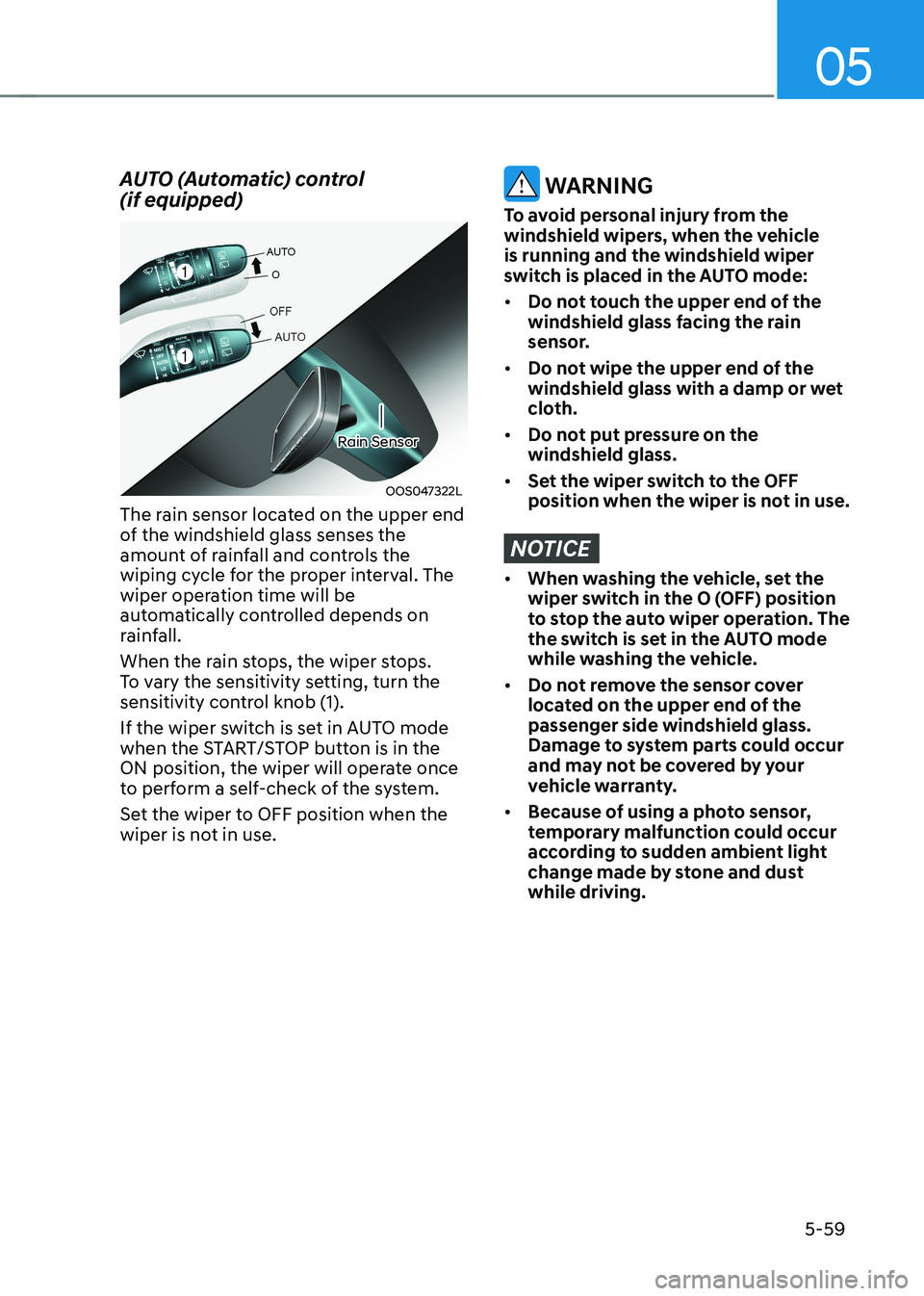
OOS047322L
Rain Sensor
The rain sensor located on the upper end
of the windshield glass senses the
amount of rainfall and controls the
wiping cycle for the proper interval. The
wiper operation time will be
automatically controlled depends on
rainfall.
When the rain stops, the wiper stops.
To vary the sensitivity setting, turn the
sensitivity control knob (1).
If the wiper switch is set in AUTO mode
when the START/STOP button is in the
ON position, the wiper will operate once
to perform a self-check of the system.
Set the wiper to OFF position when the
wiper is not in use.
WARNING
To avoid personal injury from the
windshield wipers, when the vehicle is running and the windshield wiper
switch is placed in the AUTO mode: • Do not touch the upper end of the
windshield glass facing the rain
sensor.
• Do not wipe the upper end of the
windshield glass with a damp or wet
cloth.
• Do not put pressure on the windshield glass.
• Set the wiper switch to the OFF
position when the wiper is not in use.
NOTICE
• When washing the vehicle, set the
wiper switch in the O (OFF) position
to stop the auto wiper operation. The
the switch is set in the AUTO mode
while washing the vehicle.
• Do not remove the sensor cover
located on the upper end of the passenger side windshield glass.
Damage to system parts could occur
and may not be covered by your
vehicle warranty.
• Because of using a photo sensor,
temporary malfunction could occur
according to sudden ambient light
change made by stone and dust while driving.
Page 256 of 548
Convenient features
5-72
Air conditioning
HYUNDAI Air Conditioning Systems are
filled with R-134a or R-1234yf refrigerant.
1. Start the vehicle. Push the air
conditioning button.
Set the mode to the (
) position.
2. Set the air intake control to recirculation mode temporarily to
allow the cabin to cool quickly. When
the desired temperature in the cabin
is reached, change the air intake
control back to Fresh mode.
3. Adjust the fan speed control and temperature control to maintain
maximum comfort.
Information
Your vehicle is filled with R-134a or
R-1234yf according to the regulation in
your country at the time of production.
You can find out which air conditioning
refrigerant is applied to your vehicle on
the label located inside of the hood. Refer
to chapter 5 for the location of the air
conditioning refrigerant label.
NOTICE
• The refrigerant system should only
be serviced by trained and certified
technicians to insure proper and safe
operation.
• The refrigerant system should be
serviced in a well-ventilated place.
• The air conditioning evaporator
(cooling coil) should never be
repaired or replaced with one
removed from a used or salvaged
vehicle and new replacement MAC
evaporators should be certified (and
labeled) as meeting SAE Standard J2842.
NOTICE
When opening the windows in humid
weather air conditioning may create
water droplets inside the vehicle. Since
excessive water droplets may cause
damage to electrical equipment, air
conditioning should only be used with
the windows closed.