2022 FORD F-650/750 lock
[x] Cancel search: lockPage 241 of 379
It is very important to use prediluted
coolant approved to the correct
specification in order to avoid plugging the
small passageways in the engine cooling
system. See Cooling System Capacity
and Specification (page 296). Do not mix
different colors or types of coolant in your
vehicle. Mixing of engine coolants or using
an incorrect coolant may harm the engine
or cooling system components and may
not be covered by the vehicle Warranty.
Note: Coolants marketed for all makes and
models may not be approved to our
specifications and may cause damage to
the cooling system. Resulting component
damage may not be covered by the vehicle
Warranty.
If the coolant level is at or below the
minimum mark, add prediluted coolant
immediately.
For vehicles with overflow coolant systems
with a non-pressurized cap on the coolant
recovery system, add coolant to the
coolant recovery reservoir when the engine
is cool. Add prediluted coolant to the
maximum level. For all vehicles which have
a coolant degas system with a pressurized
cap, or if it is necessary to remove the
coolant pressure relief cap on the radiator,
follow these steps to add engine coolant:
1. Turn the engine off and let it cool.
2. Unscrew the cap slowly. Any pressure escapes as you unscrew the cap.
3. Fill the coolant reservoir slowly with prediluted engine coolant to within the
minimum and maximum range on the
engine coolant reservoir. If you
removed the radiator cap in an
overflow system, fill the radiator until
the coolant is visible and the radiator
is almost full. If coolant is added to
bring the level within the minimum and
maximum range when the engine is not
cold, the system may remain
underfilled. 4.
Replace the coolant reservoir cap. Turn
the cap clockwise until it contacts the
hard stop.
5. Check the coolant level in the coolant reservoir the next few times you drive
your vehicle. If necessary, add enough
prediluted engine coolant to bring the
coolant level to the proper level.
Note: If prediluted coolant is not available,
use the approved antifreeze concentrate
diluting it to 50/50 with distilled water. See
Cooling System Capacity and
Specification (page 296). Using water that
has not been deionized may contribute to
deposit formation, corrosion or plugging of
the small cooling system passageways.
If you have to add more than
1.1 qt (1 L) of
engine coolant per month, have your
vehicle checked as soon as possible.
Operating an engine with a low level of
coolant can result in engine overheating
and possible engine damage.
Note: During normal vehicle operation, the
coolant may change color from orange to
pink or light red. As long as the coolant is
clear and uncontaminated, this color change
does not indicate the coolant has degraded
nor does it require the coolant to be drained,
the system to be flushed, or the coolant to
be replaced.
Note: In case of emergency, you can add a
large amount of water without coolant in
order to reach a vehicle service location.
Water alone, without coolant, can cause
engine damage from corrosion, overheating
or freezing. When you reach a service
location, you must have the cooling system
drained, flushed and refilled using the
correct specification prediluted coolant or
antifreeze concentrate. See
Cooling
System Capacity and Specification (page
296
).
238
2022 F650750 (TBC) , enUSA, Edition date: 202010, Second-Printing Maintenance
Page 249 of 379

5. Turn the air conditioning (if equipped)
on and allow the engine to idle for at
least one minute.
6. Release the parking brake. With your foot on the brake pedal and with the
air conditioning on, put the vehicle in
drive (D) and allow the engine to idle
for at least one minute.
•If you do not allow the engine to
relearn its idle trim, the idle quality
of your vehicle may be adversely
affected until the idle trim is
eventually relearned.
7. Drive the vehicle to complete the relearning process
•The vehicle may need to be driven
10 mi (16 km) or more to relearn the
idle and fuel trim strategy along
with the ethanol content for flexible
fuel vehicles.
If the battery has been disconnected or a
new battery has been installed, the clock
and radio settings must be reset once the
battery is reconnected.
Always dispose of automotive
batteries in a responsible manner.
Follow your local authorized standards
for disposal. Call your local authorized
recycling center to find out more about
recycling automotive batteries.
Battery Management System (If
Equipped)
The battery management system (BMS)
monitors battery conditions and takes
actions to extend battery life. If excessive
battery drain is detected, the system may
temporarily disable certain electrical
features to protect the battery. Those
electrical accessories affected include the
rear defrost, heated/cooled seats, climate
control fan, heated steering wheel, audio
and navigation system. A message may be
shown in the information displays to alert the driver that battery protection actions
are active. These messages are only for
notification that an action is taking place,
and not intended to indicate an electrical
problem or that the battery requires
replacement.
Electrical accessory installation
To ensure proper operation of the BMS,
any electrical devices that are added to
the vehicle should not have their ground
connection made directly at the negative
battery post. A connection at the negative
battery post can cause inaccurate
measurements of the battery condition
and potential incorrect system operation.
Note:
Electrical or electronic accessories
added to the vehicle by the dealer or the
owner may adversely affect battery
performance and durability, and may also
affect the performance of other electrical
systems in the vehicle.
When a battery replacement is required,
the battery should only be replaced with
a Ford recommended replacement battery
which matches the electrical requirements
of the vehicle. After battery replacement,
or in some cases after charging the battery
with the external charger, the BMS requires
eight hours of vehicle sleep time (key off
with doors closed) to relearn the new
battery state of charge. Prior to relearning
the state of charge, the BMS may disable
electrical features (to protect the battery)
earlier than normal.
ADJUSTING THE HEADLAMPS
Vertical Aim Adjustment
The headlamps on your vehicle are
properly aimed at the assembly plant. If
your vehicle has been in an accident, the
alignment of your headlamps should be
checked by your authorized dealer.
246
2022 F650750 (TBC) , enUSA, Edition date: 202010, Second-Printing Maintenance
Page 250 of 379

Headlamp Aiming Target
8 ft (2.4 m)
A
Center height of lamp to ground
B
25 ft (7.6 m)
C
Horizontal reference line
D
Vertical Aim Adjustment Procedure
1. Park the vehicle directly in front of a wall or screen on a level surface,
approximately 25 ft (7.6 m) away.
2. Measure the height of the headlamp bulb center from the ground and mark
an
8 ft (2.4 m) horizontal reference line
on the vertical wall or screen at this
height.
Note: To see a clearer light pattern for
adjusting, you may want to block the light
from one headlamp while adjusting the
other.
3. Turn on the low beam headlamps to illuminate the wall or screen and open
the hood. 4. On the wall or screen you will observe
a flat zone of high intensity light
located at the top of the right hand
portion of the beam pattern. If the top
edge of the high intensity light zone is
not at the horizontal reference line, the
headlamp will need to be adjusted. 5. Locate the vertical adjuster on each
headlamp. Using a Phillips #2
screwdriver, turn the adjuster either
clockwise or counterclockwise in order
to adjust the vertical aim of the
headlamp.
6. Repeat Steps 3 thru 5 to adjust the other headlamp.
7. Close the hood and turn off the lamps.
Horizontal Aim Adjustment
Horizontal aim is not required for this
vehicle and is not adjustable.
247
2022 F650750 (TBC) , enUSA, Edition date: 202010, Second-Printing MaintenanceE142592 E142465 E163806
Page 251 of 379
WASHER FLUID CHECK
WARNING: If you operate your
vehicle in temperatures below 40°F
(5°C), use washer fluid with antifreeze
protection. Failure to use washer fluid
with antifreeze protection in cold
weather could result in impaired
windshield vision and increase the risk
of injury or accident.
Add fluid to fill the reservoir if the level is
low. Only use a washer fluid that meets
Ford specifications. See
Capacities and
Specifications (page 286).
State or local regulations on volatile
organic compounds may restrict the use
of methanol, a common windshield washer
antifreeze additive. Washer fluids
containing non-methanol antifreeze
agents should be used only if they provide
cold weather protection without damaging
the vehicle ’s paint finish, wiper blades or
washer system.
FUEL FILTER - 7.3L
Your vehicle is equipped with a lifetime
fuel filter that is integrated with the fuel
tank. Regular maintenance or replacement
is not needed.
CHECKING THE WIPER
BLADES Run the tip of your fingers over the edge of
the blade to check for roughness.
Clean the wiper blades with washer fluid
or water applied with a soft sponge or
cloth.
CHANGING THE WIPER
BLADES
You can manually move the wiper arms
when the ignition is off. This allows for ease
of blade replacement and cleaning under
the blades.
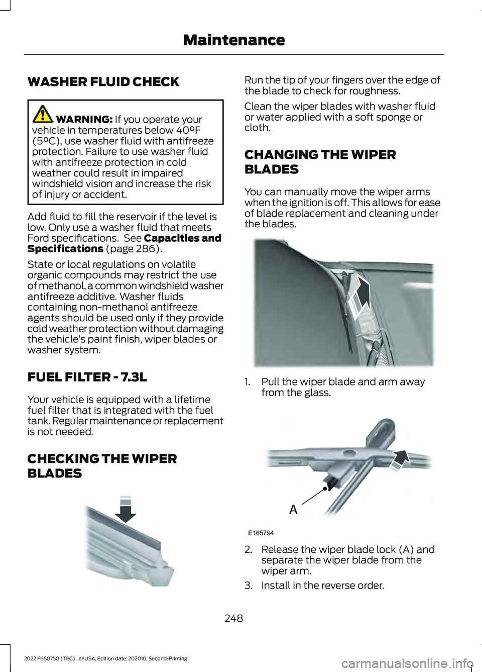
1. Pull the wiper blade and arm away
from the glass. 2. Release the wiper blade lock (A) and
separate the wiper blade from the
wiper arm.
3. Install in the reverse order.
248
2022 F650750 (TBC) , enUSA, Edition date: 202010, Second-Printing MaintenanceE142463 E165804 A
E165794
Page 252 of 379

Note:
Make sure that the wiper blade locks
into place. Lower the wiper arm and blade
back on the windshield. The wiper arms will
automatically return to their normal position
when you turn the ignition on.
• Replace wiper blades at least once per
year for optimum performance.
• You can improve poor wiper quality by
cleaning the wiper blades and the
windshield.
REMOVING A HEADLAMP 1. Remove the four bolts from the
headlamp assembly.
2. Pull the assembly straight out disengaging one snap clip from the
fender.
3. Disconnect the electrical connector by
squeezing the release tab and pushing
the connector forward, then pulling it
rearward.
CHANGING A BULB WARNING: Bulbs can become hot.
Let the bulb cool down before removing
it. Failure to do so could result in
personal injury. Headlamp bulbs must be marked with an
authorized D.O.T. marking for North
America to make sure they have the proper
lamp performance, light brightness, light
pattern and safe visibility.
Install in the reverse order unless otherwise
stated.
Headlamp Bulbs
1.
Switch all of the lamps and the ignition
off.
2. Remove the headlamp. See Removing a Headlamp (page 249).
3. Release the clip and remove the bulb.
Note: Do not touch the bulb glass.
Note: If the bulb is accidentally touched, it
should be cleaned with rubbing alcohol
before being used.
Front Clearance and Identification
Lamp
(If Equipped) 1.
Switch all of the lamps and the ignition
off.
2. Remove the screw and lens from the lamp assembly.
3. Press the bulb in and turn the bulb counterclockwise to remove it.
249
2022 F650750 (TBC) , enUSA, Edition date: 202010, Second-Printing MaintenanceE163822 E163825
Page 254 of 379
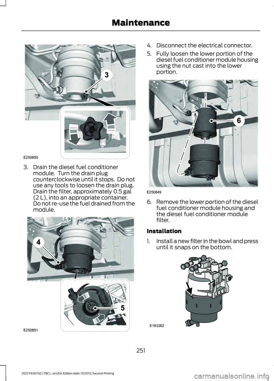
3. Drain the diesel fuel conditioner
module. Turn the drain plug
counterclockwise until it stops. Do not
use any tools to loosen the drain plug.
Drain the filter, approximately 0.5 gal
(2 L), into an appropriate container.
Do not re-use the fuel drained from the
module. 4. Disconnect the electrical connector.
5. Fully loosen the lower portion of the
diesel fuel conditioner module housing
using the nut cast into the lower
portion. 6.
Remove the lower portion of the diesel
fuel conditioner module housing and
the diesel fuel conditioner module
filter.
Installation
1. Install a new filter in the bowl and press
until it snaps on the bottom. 251
2022 F650750 (TBC) , enUSA, Edition date: 202010, Second-Printing MaintenanceE250850 E250851 E250849 E163362
Page 255 of 379
2.
Install the lower portion of the housing
on the top portion. Tighten by hand
until you feel a strong resistance.
Continue to tighten with a 32mm
socket wrench until the mechanical
stop on the bottom meets the top.
3. Connect the electrical connector.
4. Tighten the drain plug, turn it clockwise
until it stops and you feel a strong
resistance. Do not use any tools to
tighten the drain plug.
5. Switch the ignition on for 30 seconds and then switch the ignition off.
Repeat this operation six times in a row
to purge any trapped air from the fuel
system.
Engine-mounted Fuel Filter
Although the fuel system is not fully
pressurized when the vehicle is off, some
residual pressure may remain in the fuel
system since it can take some time for the
pressure to completely bleed off.
Therefore, we recommend you place an
absorbent cloth below the filter connectors
to absorb any fuel that may drain.
The engine-mounted fuel filter is a plastic
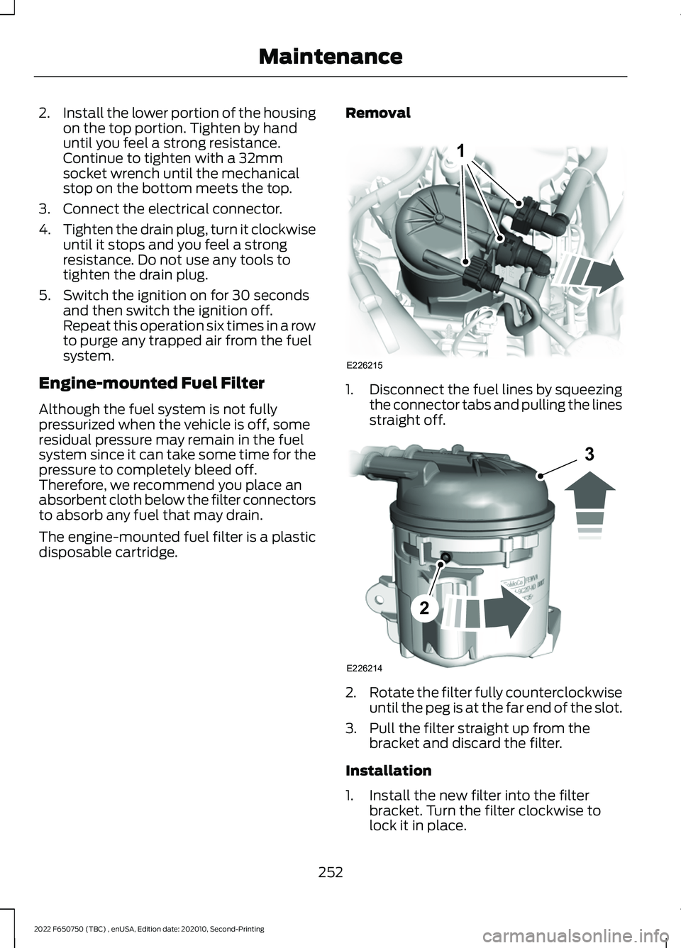
disposable cartridge. Removal 1.
Disconnect the fuel lines by squeezing
the connector tabs and pulling the lines
straight off. 2.
Rotate the filter fully counterclockwise
until the peg is at the far end of the slot.
3. Pull the filter straight up from the bracket and discard the filter.
Installation
1. Install the new filter into the filter bracket. Turn the filter clockwise to
lock it in place.
252
2022 F650750 (TBC) , enUSA, Edition date: 202010, Second-Printing MaintenanceE226215
1 E226214
2
3
Page 257 of 379
Before engine operation, remove any debris
blocking the core.
•
Turbocharger-to-charge air cooler.
• Charge air cooler-to-intake manifold
pipe.
• Mounting bracket.
• Chassis-mounted charge air cooler
core.
Inspect air intake piping:
• Check for accumulation of salt
deposits (where applicable). If present,
disassemble and clean the complete
air intake piping system. If pitting is
evident on the intake piping, use
Motorcraft Silicone Gasket and Sealant
TA-30 to seal joints against leakage.
• Check for loose hoses and clamps.
• Check for ruptured or collapsed hoses.
• Check air cleaner housing for cracks.
EXHAUST SYSTEM
INSPECTION
Note: If your vehicle is equipped with a
catalytic converter or muffler, do not blend
waste oil with diesel fuel. Operate only on
ultra-low sulfur (less than 15 parts per
million sulfur) diesel fuel with a cetane
value of 45 or higher.
If your diesel engine is equipped with a
catalytic converter, it is important to review
the maintenance schedule to make sure
proper functioning of the catalytic
converter. Also, take precautions not to
damage the catalytic converter when
servicing your engine or storing your
vehicle. BRAKE SYSTEM INSPECTION WARNING: Always wear a
respirator approved by the National
Institute of Occupational Studies of
Health (NIOSH) or Mine Safety and
Appliance (MSA) during all brake service
procedures. Wear the respirator from
removal of the wheels through assembly.
Never use compressed air or dry brushing
to clean brake parts or assemblies.
Clean brake parts and assemblies in
open air. During assembly, carefully
place all parts on the floor to avoid
getting dust in the air. Use an industrial
vacuum cleaner with a HEPA filter
system to clean dust from the brake
drums, backing plates and other brake
parts. After using the vacuum, remove
any remaining dust with a rag soaked in
water and wrung until nearly dry.
Never use compressed air or dry
sweeping to clean the work area. Use an
industrial vacuum cleaner with a HEPA
filter system and rags soaked in water
and wrung until nearly dry. Dispose of
used rags with care to avoid getting dust
in the air. Use an approved respirator
when emptying vacuum cleaners and
handling used rags.
Worker clean-up: Wash your hands
before eating, drinking or smoking.
Vacuum your work clothes after use and
then launder them separately, without
shaking them, to prevent fiber dust
getting into the air.
Your vehicle is equipped with
non-asbestos brake linings. However,
exposure to excessive amounts of brake
material (whether asbestos or
non-asbestos, fiberglass, mineral wool,
aramid or carbon) may be a serious health
hazard.
254
2022 F650750 (TBC) , enUSA, Edition date: 202010, Second-Printing Maintenance