2021 VOLKSWAGEN TRANSPORTER lock
[x] Cancel search: lockPage 245 of 486
230-volt power supply
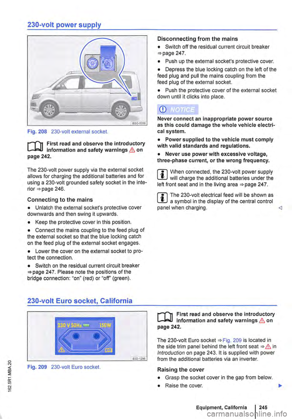
Fig. 208 230-volt external socket.
r-'('n First read and observe the introductory l.-Jo:-11 Information and safety warnings & on page 242.
The 230-volt power supply via the external socket allows for charging the additional batteries and for using a 230-volt grounded safety socket in the inte-rior 246.
Connecting to the mains
• Unlatch the external socket's protective cover downwards and then swing it upwards.
• Keep the protective cover in this position.
• Connect the mains coupling to the feed plug of the external socket so that the blue locking catch on the feed plug of the external socket engages.
• Lower the cover on the external socket to pro-tect the connection.
• Switch on the residual current circuit breaker 247. Please note the positions of the bridge connection: "on" (red) or "off' (green).
230-volt Euro socket, California
Disconnecting from the mains
• Switch off the residual current circuit breaker 247.
• Push up the external socket's protective cover.
• Depress the blue locking catch on the left of the feed plug and pull the mains coupling from the feed plug of the external socket.
• Push the protective cover of the external socket down until it clicks into place.
CD
Never connect an inappropriate power source as this could damage the whole vehicle electri-cal system.
• Power supplied to the vehicle must comply with valid standards and regulations.
• Never use power with excessive voltage, three-phase current, or the wrong frequency.
m When connected, the 230-volt power supply l!J will charge the additional batteries under the left front seat and in the living area 247.
m The 230-volt electrical feed will be shown as l!J a symbol in the display of the central control panel when charging.
The 230-volt Euro socket 209 is located in the side trim panel behind the left front seat & in Introduction on page 243. it is supplied with power L..---------------"'"30::c·.::."='" from the additional batteries via an inverter.
Fig. 209 230-volt Euro socket. Raising the cover
• Grasp the socket cover in the gap from below.
• Raise the cover. .,.
Equipment, California 245
Page 246 of 486
Inserting the Euro plug
• Plug the Euro plug into the Euro socket. The child safety function will disengage at the same time. Electricity will not flow until the child lock has been unlocked.
• Push the Euro plug all the way into the Euro socket so that it is firmly in place and will not fall out as a result of vibration or other vehicle motion.
LEDs above the socket
Constant green light The child lock is disen-gaged. The Euro socket is ready for use.
Flashing red light A fault has occurred. for example cut-off due to excess current or tem-perature.
Compatible devices
Electrical devices with a Euro plug can be connec-ted to the 230-volt Euro socket in the side trim pan-el behind the left front seat.
230-volt grounded safety socket
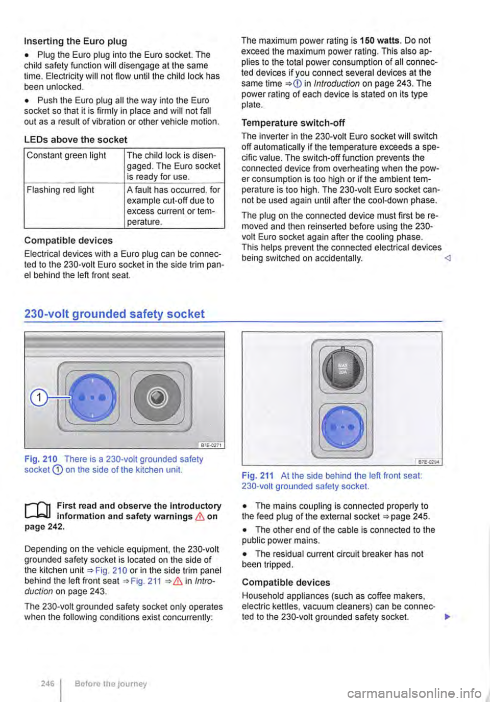
Fig. 210 There is a 230-volt grounded safety socket Q) on the side of the kitchen unit.
r--T'n First read and observe the Introductory L-k.U information and safety warnings & on page 242.
Depending on the vehicle equipment, the 230-volt grounded safety socket is located on the side of the kitchen unit 210 or in the side trim panel behind the left front seat 211 Intro-duction on page 243.
The 230-volt grounded safety socket only operates when the following conditions exist concurrently:
246 I Before the journey
The maximum power rating is 150 watts. Do not exceed the maximum power rating. This also ap-plies to the total power consumption of all connec-ted devices if you connect several devices at the same time in Introduction on page 243. The power rating of each device is stated on its type plate.
Temperature switch-off
The inverter in the 230-volt Euro socket will switch off automatically if the temperature exceeds a spe-cific value. The switch-off function prevents the connected device from overheating when the pow-er consumption is too high or if the ambient tem-perature is too high. The 230-volt Euro socket can-not be used again until after the cool-down phase.
The plug on the connected device must first be re-moved and then reinserted before using the 230-volt Euro socket again after the cooling phase. This helps prevent the connected electrical devices being switched on accidentally. <1
B7E.Q29.4
Fig. 211 At the side behind the left front seat: 230-volt grounded safety socket.
• The mains coupling is connected properly to the feed plug of the external socket 245.
• The other end of the cable is connected to the public power mains.
• The residual current circuit breaker has not been tripped.
Compatible devices
Household appliances (such as coffee makers, electric kettles, vacuum cleaners) can be connec-ted to the 230-volt grounded safety socket. .,.
Page 249 of 486
Fuses for the camping equipment
87E-0221
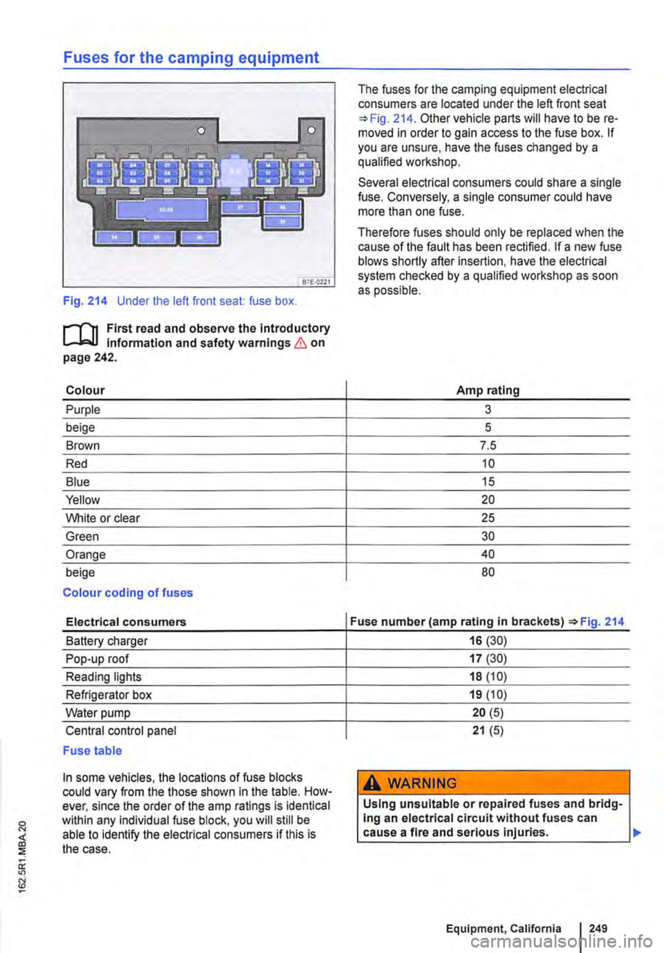
Fig. 214 Under the left front seat: fuse box.
l"""'('n First read and observe the introductory L-Jr:,.U information and safety warnings & on page 242.
Colour
Purple
beige
Brown
Red
Blue
Yellow
White or clear
Green
Orange
beige
Colour coding of fuses
Electrical consumers
Battery charger
Pop-up roof
Reading lights
Refrigerator box
Water pump
Central control panel
Fuse table
In some vehicles, the locations of fuse blocks could vary from the those shown In the table. How-ever, since the order of the amp ratings is identical within any individual fuse block, you will still be able to identify the electrical consumers if this is the case.
The fuses for the camping equipment electrical consumers are located under the left front seat 214. Other vehicle parts will have to be re-moved in order to gain access to the fuse box. If you are unsure, have the fuses changed by a qualified workshop.
Several electrical consumers could share a single fuse. Conversely, a single consumer could have more than one fuse.
Therefore fuses should only be replaced when the cause of the fault has been rectified. If a new fuse blows shortly after insertion, have the electrical system checked by a qualified workshop as soon as possible.
Amp rating
3
5
7.5
10
15
20
25
30
40
80
Fuse number (amp rating in Fig. 214
16 (30)
17 (30)
18 (10)
19 (10)
20 (5)
21 (5)
A WARNING
Using unsuitable or repaired fuses and bridg-Ing an electrical circuit without fuses can cause a fire and serious injuries.
Equipment, California 249
Page 250 of 486
A WARNING (Continued)
• Never fit fuses that have a higher fuse pro-tection limit. Fuses must always be replaced by a new fuse with the same amp rating (same colour and markings) and size.
• Never repair a fuse.
• Never use a metal strip, paper clip or simi-lar objects to replace a fuse.
CD
• To avoid damage to the electrical system in the vehicle, switch the ignition, the lights and all electrical consumers off and remove the ve-hicle key from the ignition before changing a fuse.
• You can damage another position in the electrical system by using a fuse with a higher amp rating.
• Fuse boxes must be protected from dirt and moisture when opened. Dirt and moisture in the fuse boxes can damage the electrical system.
o::n Introduction
This chapter contains information on the following subjects:
Controls for the living area 250
Controls for the living area
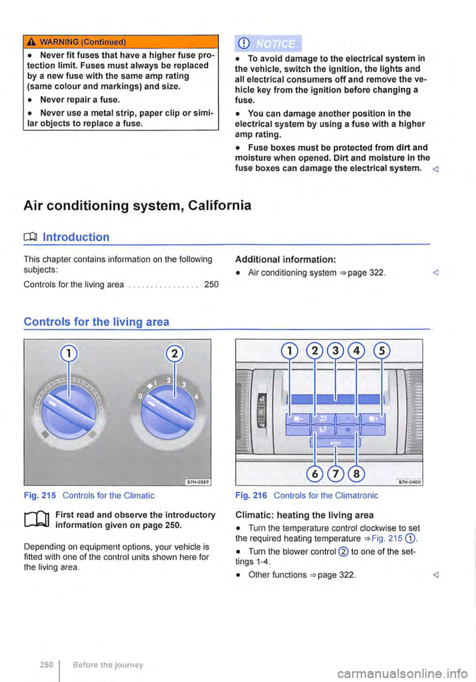
Fig. 215 Controls for the Climatic
ifl1 First read and observe the introductory L-.J.=.IJ information given on page 250.
Depending on equipment options, your vehicle is fitted with one of the control units shown here for the living area.
250 I Before the journey
Additional information:
• Air conditioning system 322.
Fig. 216 Controls for the Climatronic
Climatic: heating the living area
• Turn the temperature control clockwise to set the required heating temperature 215 G).
• Turn the blower control @ to one of the set-tings 1-4.
Page 254 of 486

Cleaning the cooker and sink
Clean the surfaces of the gas cooker and sink with commercially available non-abrasive cleaning Remove the pan supports from atop the burners to clean the surface of the gas cooker.
When cleaning the gas cooker, make sure that you do not damage or bend the heat sensors on the burners.
The gas burners should be cleaned with a brush at regular intervals.
CD
Abrasive sponges and cleaning agents can scratch and otherwise damage surfaces.
CD
Cleaning products that contain solvents, e.g. acetone, paint thinner, attack the material and can cause damage. <1
Cleaning the display of the central control panel
CD r-l'n First read and observe the Introductory L-l.::JJ information given on page 252. Do not use solvents such as turpentine or pet-
When cleaning the display, use an anti-static cloth or anti-static agent in order to prevent the build up of static charge on the display, which could render the display symbols unrecognizable
rol to clean the display, as these will damage lt.
[]J First read and observe the introductory information given on page 252.
Fault Possible cause Solution
Supplementary 1. The fuel tank is empty. 1. Fill up with fuel. heating system is malfunctioning or not working at all
2. There is a defective fuse 2. Replace the fuse 249. 429 and 249.
3. The warm air vent is blocked. 3. Remove objects blocking the air intake or warm air vents.
4. Battery voltage too low. 4. Charge the battery using the battery charger or by running the engine.
5. The switch-on time is not program-5. Properly program the switch-on time. med or is incorrectly programmed.
6. The central control panel is not 6. Switch on the central control panel. switched on.
1. Electrical consumers have been 1. Charge the battery using the battery Battery voltage switched on and caused the voltage of charger or by running the engine. too low the additional battery to drop to 10.5 volts or below.
2. The battery charger is malfunction-2. Check the residual current circuit breaker ing. or have the battery charger checked by a qualified workshop.
Battery charger is 1. There is a defective fuse 1. Replace fuse =>page 249. not charging the 429 and 249. battery.
254 Before the journey
Page 255 of 486
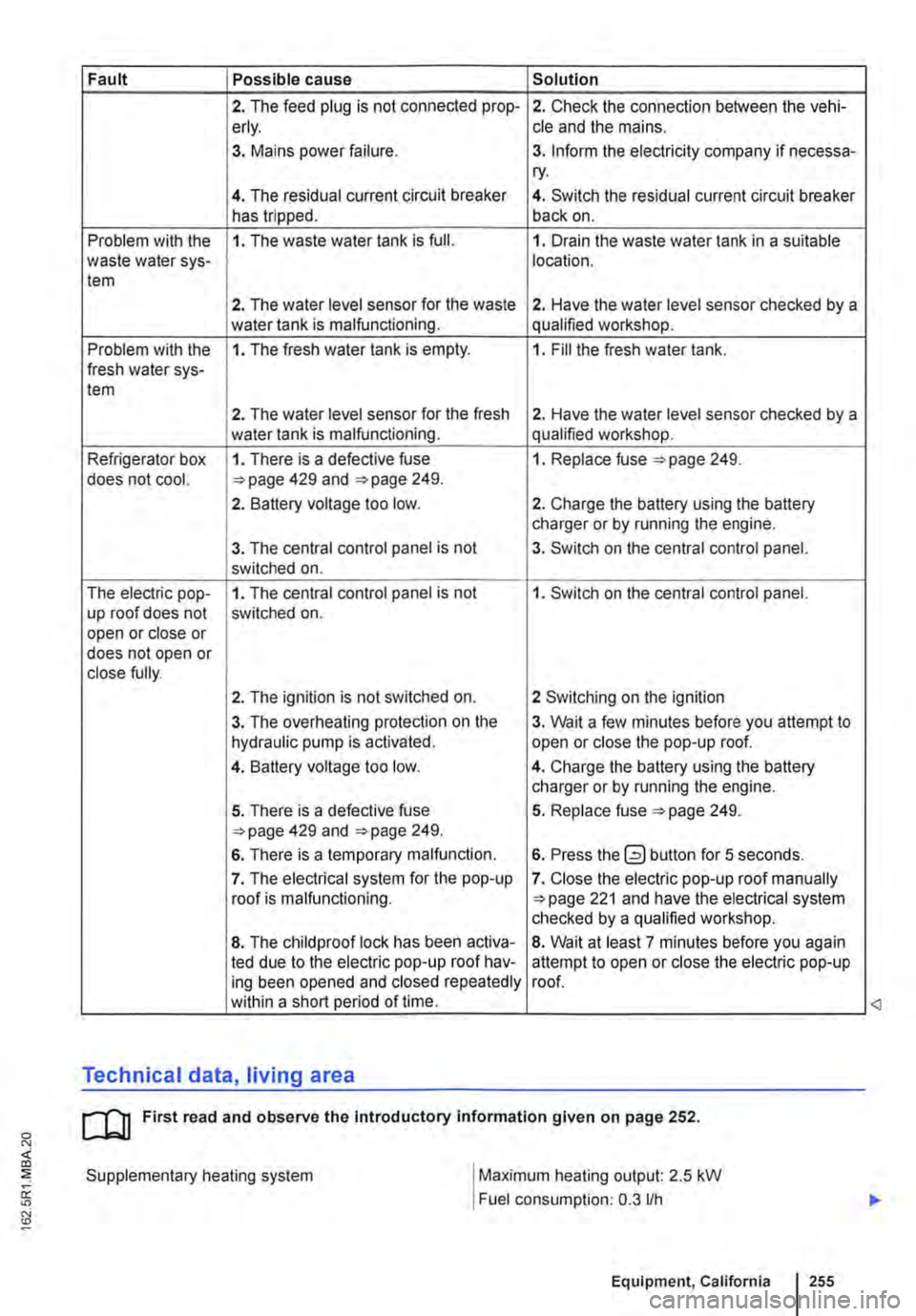
Fault Possible cause Solution
2. The feed plug is not connected prop-2. Check the connection between the vehi-erly. cle and the mains.
3. Mains power failure. 3. Inform the electricity company if necessa-ry.
4. The residual current circuit breaker 4. Switch the residual current circuit breaker has tripped. back on.
Problem with the 1. The waste water tank is full. 1. Drain the waste water tank in a suitable waste water sys-location. tem
2. The water level sensor for the waste 2. Have the water level sensor checked by a water tank is malfunctioning. qualified workshop.
Problem with the 1. The fresh water tank is empty. 1. Fill the fresh water tank. fresh water sys-tem
2. The water level sensor for the fresh 2. Have the water level sensor checked by a water tank is malfunctioning. qualified workshop.
Refrigerator box 1. There is a defective fuse 1. Replace fuse 249. does not cool. 429 and 249.
2. Battery voltage too low. 2. Charge the battery using the battery charger or by running the engine.
3. The central control panel is not 3. Switch on the central control panel. switched on.
The electric pop-1. The central control panel is not 1. Switch on the central control panel. up roof does not switched on. open or close or does not open or close fully.
2. The ignition is not switched on. 2 Switching on the ignition
3. The overheating protection on the 3. Wait a few minutes before you attempt to hydraulic pump is activated. open or close the pop-up roof.
4. Battery voltage too low. 4. Charge the battery using the battery charger or by running the engine.
5. There is a defective fuse 5. Replace fuse 249. 429 and 249.
6. There is a temporary malfunction. 6. Press the button for 5 seconds.
7. The electrical system for the pop-up 7. Close the electric pop-up roof manually roof is malfunctioning. 221 and have the electrical system checked by a qualified workshop.
8. The child proof lock has been activa-8. Wait at least 7 minutes before you again led due to the electric pop-up roof hav-attempt to open or close the electric pop-up ing been opened and closed repeatedly roof. within a short period of time.
Technical data, living area
cu First read and observe the Introductory information given on page 252.
Supplementary heating system
I
Maximum heating output: 2.5 kW
Fuel consumption: 0.3 lfh
Equipment, California I 255
<3
Page 257 of 486
While driving
Starting the engine, changing gear and parking
Starting and stopping the engine
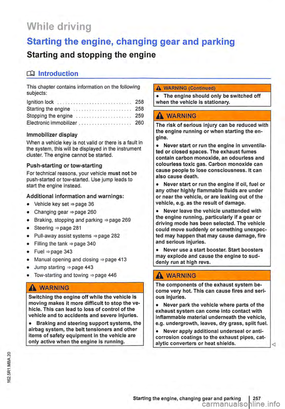
o::n Introduction
This chapter contains information on the following subjects:
Ignition lock . . ......•........ 258
Starting the engine . . . . . • . • . . . . . . . . 258
Stopping the engine . . . . . . . . . . . . . . . . . . . . . 259
Electronic immobilizer . . . . . . . . . • . . . . . . . . . . 260
Immobilizer display
When a vehicle key is not valid or there is a fault in the system, this will be displayed in the Instrument cluster. The engine cannot be started.
Push-starting or tow-starting
For technical reasons, your vehicle must not be push-started or tow-started. Use jump leads to start the engine instead.
Additional information and warnings:
• Vehicle key set =>page 36
• Changing gear =>page 260
• Braking, stopping and parking =>page 269
• Steering =>page 281
• Pull-away assist systems =>page 282
• Filling the tank =>page 340
• Fuel =>page 343
• Manual opening and dosing =>page 413
• Jump starting =>page 443
• Tow-starting and towing =>page 446
A WARNING
Switching the engine off while the vehicle Is moving makes it more difficult to stop the ve-hicle. This can lead to loss of control of the vehicle and to accidents and severe Injuries.
• Braking and steering support systems, the alrbag system, the belt tens loners and other items of safety equipment in the vehicle are only active when the engine is running.
A WARNING (Continued)
• The engine should only be switched off when the vehicle Is stationary.
A WARNING
The risk of serious Injury can be reduced with the engine running or when starting the en-glne.
• Never start or run the engine In unventlla-ted or closed spaces. The exhaust fumes contain carbon monoxide, an odourless and colourless toxic gas. Carbon monoxide can cause people to lose consciousness. it can also cause death.
• Never start or run the engine if oil, fuel or any other highly flammable fluids are under or near the vehicle, or are leaking out of the vehicle, e.g. as the result of damage.
• Never leave the vehicle unattended with the engine running, particularly if a gear or driving mode has been selected. The vehicle could move suddenly or something unexpec-ted may happen that may cause damage, fire and serious Injuries.
• Never use a start booster. Start boosters may explode and cause the engine to sud-denly run at high revs.
A WARNING
The components of the exhaust system be-come very hot. This can cause fires and sari-ous Injuries.
• Never park the vehicle where parts of the exhaust system can come Into contact with Inflammable material underneath the vehicle, e.g. undergrowth, leaves, dry grass, split fuel.
• Never apply additional undersea! or anti-corrosion coatings to the exhaust pipes, cat-a lytic converters or heat shields.
Starting the engine, changing gear and parking I 257
Page 258 of 486
Ignition lock
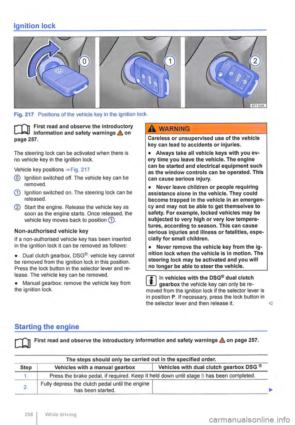
Fig. 217 Positions of the vehicle key in the ignition lock .
.--m First read and observe the introductory Information and safety warnings & on page 257.
The steering lock can be activated when there is no vehicle key in the ignition lock.
Vehicle key positions :) Fig. 217
@ Ignition switched off. The vehicle key can be removed.
G) Ignition switched on. The steering lock can be released.
® Start the engine. Release the vehicle key as soon as the engine starts. Once released. the vehicle key moves back to position G).
Non-authorised vehicle key
If a non-authorised vehicle key has been inserted in the ignition lock it can be removed as follows:
• Dual clutch gearbox, DSG®: vehicle key cannot be removed from the ignition lock in this position. Press the lock button in the selector lever and re-lease. The vehicle key can be removed.
• Manual gearbox: remove the vehicle key from the ignition lock.
Starting the engine
A WARNING
Careless or unsupervised use of the vehicle key can lead to accidents or Injuries.
• Always take all vehicle keys with you ev-ery time you leave the vehicle. The engine can be started and electrical equipment such as the window controls can be operated. This can cause serious Injury.
• Never leave children or people requiring assistance alone In the vehicle. They could become trapped In the vehicle in an emergen-cy and may not be able to get themselves to safety. For example, locked vehicles may be subjected to very high or very low tempera-tures, according to season. This can cause serious Injuries and Illness or fatalities, espe-cially for small children.
• Never remove the vehicle key from the ig-nition lock when the vehicle Is In motion. The steering lock may be activated and you will no longer be able to steer the vehicle.
m In vehicles with the DSG® dual clutch W gearbox the vehicle key can only be re-moved from the Ignition lock if the selector lever is in position P. If necessary, press the lock button in the selector lever and then release it.
The steps should only be carried out In the specified order.
Step Vehicles with a manual gearbox I Vehicles with dual clutch gearbox DSG ®
1. Press the brake pedal, if required. Keep it held down until stage 5 has been completed.
Fully depress the clutch pedal until the engine I
___
258 I While drivong