2021 RAM PROMASTER CITY parking brake
[x] Cancel search: parking brakePage 189 of 280

SAFETY187
Periodic Safety Checks You Should Make
Outside The Vehicle
Tires
Examine tires for excessive tread wear and
uneven wear patterns. Check for stones, nails,
glass, or other objects lodged in the tread or
sidewall. Inspect the tread for cuts and cracks.
Inspect sidewalls for cuts, cracks, and bulges.
Check the lug nut/bold torque for tightness.
Check the tires (including spare) for proper cold
inflation pressure.
Lights
Have someone observe the operation of brake
lights and exterior lights while you work the
controls. Check turn signal and high beam
indicator lights on the instrument panel.
Door Latches
Check for proper closing, latching, and locking.
Fluid Leaks
Check area under the vehicle after overnight
parking for fuel, coolant, oil, or other fluid leaks.
Also, if gasoline fumes are detected or if fuel or
brake fluid leaks are suspected, the cause
should be located and corrected immediately.
NEVER place any objects under the floor
mat (e.g., towels, keys, etc.). These objects
could change the position of the floor mat
and may cause interference with the accel -
erator, brake, or clutch pedals.
If the vehicle carpet has been removed and
re-installed, always properly attach carpet
to the floor and check the floor mat
fasteners are secure to the vehicle carpet.
Fully depress each pedal to check for inter -
ference with the accelerator, brake, or
clutch pedals then re-install the floor mats.
It is recommended to only use mild soap
and water to clean your floor mats. After
cleaning, always check your floor mat has
been properly installed and is secured to
your vehicle using the floor mat fasteners
by lightly pulling mat.
WARNING! (Continued)
6
21_VM_OM_EN_USC_t.book Page 187
Page 198 of 280
196IN CASE OF EMERGENCY
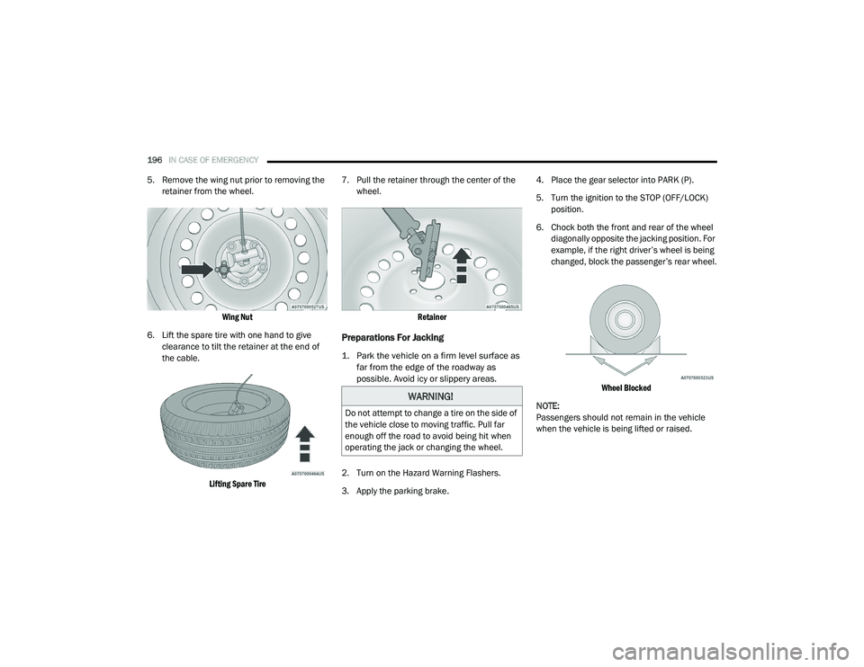
5. Remove the wing nut prior to removing the
retainer from the wheel.
Wing Nut
6. Lift the spare tire with one hand to give clearance to tilt the retainer at the end of
the cable.
Lifting Spare Tire
7. Pull the retainer through the center of the
wheel.
Retainer
Preparations For Jacking
1. Park the vehicle on a firm level surface as far from the edge of the roadway as
possible. Avoid icy or slippery areas.
2. Turn on the Hazard Warning Flashers.
3. Apply the parking brake. 4. Place the gear selector into PARK (P).
5. Turn the ignition to the STOP (OFF/LOCK)
position.
6. Chock both the front and rear of the wheel diagonally opposite the jacking position. For
example, if the right driver’s wheel is being
changed, block the passenger’s rear wheel.
Wheel Blocked
NOTE:
Passengers should not remain in the vehicle
when the vehicle is being lifted or raised.
WARNING!
Do not attempt to change a tire on the side of
the vehicle close to moving traffic. Pull far
enough off the road to avoid being hit when
operating the jack or changing the wheel.
21_VM_OM_EN_USC_t.book Page 196
Page 199 of 280
IN CASE OF EMERGENCY197
(Continued)
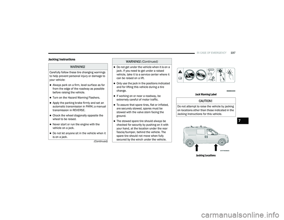
Jacking Instructions
Jack Warning Label Jacking Locations
WARNING!
Carefully follow these tire changing warnings
to help prevent personal injury or damage to
your vehicle:
Always park on a firm, level surface as far
from the edge of the roadway as possible
before raising the vehicle.
Turn on the Hazard Warning Flashers.
Apply the parking brake firmly and set an
automatic transmission in PARK; a manual
transmission in REVERSE.
Chock the wheel diagonally opposite the
wheel to be raised.
Never start or run the engine with the
vehicle on a jack.
Do not let anyone sit in the vehicle when it
is on a jack.
Do not get under the vehicle when it is on a
jack. If you need to get under a raised
vehicle, take it to a service center where it
can be raised on a lift.
Only use the jack in the positions indicated
and for lifting this vehicle during a tire
change.
If working on or near a roadway, be
extremely careful of motor traffic.
To assure that spare tires, flat or inflated,
are securely stowed, spares must be
stowed with the valve stem facing the
ground.
The stowed spare tire should always be
checked for security by pushing on it with
your hand, at the location under the rear
fascia/bumper, behind the vehicle. The
spare tire should not move when fully
secured by the winch under the vehicle.
WARNING! (Continued)
CAUTION!
Do not attempt to raise the vehicle by jacking
on locations other than those indicated in the
Jacking Instructions for this vehicle.
7
21_VM_OM_EN_USC_t.book Page 197
Page 208 of 280
206IN CASE OF EMERGENCY
See below steps to prepare for jump starting:
1. Apply the parking brake, shift the
automatic transmission into PARK (P) and
turn the ignition to STOP.
2. Turn off the heater, radio, and all electrical accessories.
3. If using another vehicle to jump-start the battery, park the vehicle within the jumper
cables reach, apply the parking brake and
make sure the ignition is OFF.
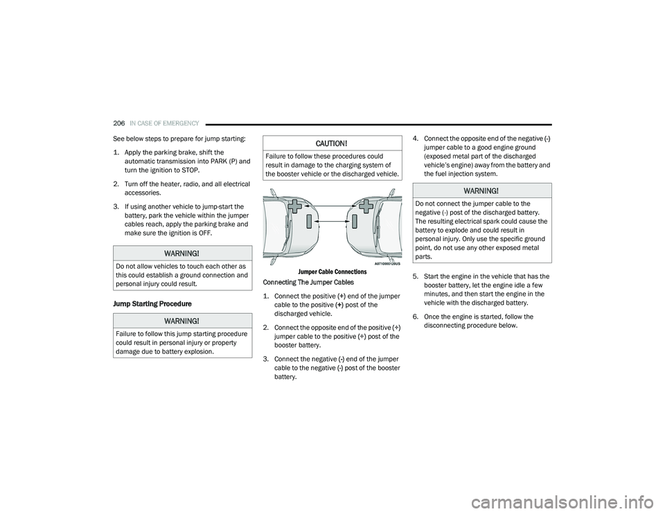
Jump Starting Procedure
Jumper Cable Connections
Connecting The Jumper Cables
1. Connect the positive
(+) end of the jumper
cable to the positive (+)
post of the
discharged vehicle.
2. Connect the opposite end of the positive (+)
jumper cable to the positive (+) post of the
booster battery.
3. Connect the negative (-) end of the jumper
cable to the negative (-) post of the booster
battery. 4. Connect the opposite end of the negative
(-)
jumper cable to a good engine ground
(exposed metal part of the discharged
vehicle’s engine) away from the battery and
the fuel injection system.
5. Start the engine in the vehicle that has the booster battery, let the engine idle a few
minutes, and then start the engine in the
vehicle with the discharged battery.
6. Once the engine is started, follow the disconnecting procedure below.
WARNING!
Do not allow vehicles to touch each other as
this could establish a ground connection and
personal injury could result.
WARNING!
Failure to follow this jump starting procedure
could result in personal injury or property
damage due to battery explosion.
CAUTION!
Failure to follow these procedures could
result in damage to the charging system of
the booster vehicle or the discharged vehicle.
WARNING!
Do not connect the jumper cable to the
negative (-) post of the discharged battery.
The resulting electrical spark could cause the
battery to explode and could result in
personal injury. Only use the specific ground
point, do not use any other exposed metal
parts.
21_VM_OM_EN_USC_t.book Page 206
Page 210 of 280
208IN CASE OF EMERGENCY
IGNITION KEY REMOVAL OVERRIDE
This vehicle is equipped with a Key Ignition Park
Interlock which requires the transmission to be
in PARK (P) before the ignition switch can be
turned to the OFF/LOCK (key removal) position.
To remove the key manually, proceed as
follows:
1. Firmly apply the parking brake.
2. Remove the Allen Key located in the rear
cargo area, in the tool bag (if equipped) or
on the left side in the cargo box.
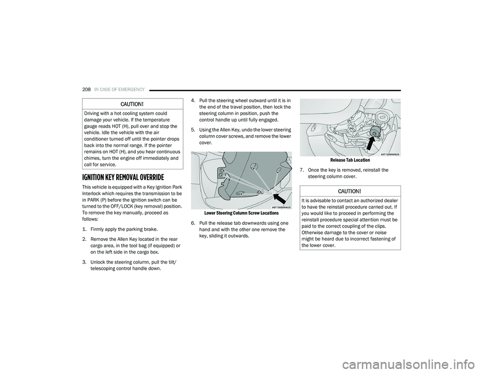
3. Unlock the steering column, pull the tilt/ telescoping control handle down. 4. Pull the steering wheel outward until it is in
the end of the travel position, then lock the
steering column in position, push the
control handle up until fully engaged.
5. Using the Allen Key, undo the lower steering column cover screws, and remove the lower
cover.
Lower Steering Column Screw Locations
6. Pull the release tab downwards using one hand and with the other one remove the
key, sliding it outwards.
Release Tab Location
7. Once the key is removed, reinstall the steering column cover.
CAUTION!
Driving with a hot cooling system could
damage your vehicle. If the temperature
gauge reads HOT (H), pull over and stop the
vehicle. Idle the vehicle with the air
conditioner turned off until the pointer drops
back into the normal range. If the pointer
remains on HOT (H), and you hear continuous
chimes, turn the engine off immediately and
call for service.
CAUTION!
It is advisable to contact an authorized dealer
to have the reinstall procedure carried out. If
you would like to proceed in performing the
reinstall procedure special attention must be
paid to the correct coupling of the clips.
Otherwise damage to the cover or noise
might be heard due to incorrect fastening of
the lower cover.
21_VM_OM_EN_USC_t.book Page 208
Page 211 of 280
IN CASE OF EMERGENCY209
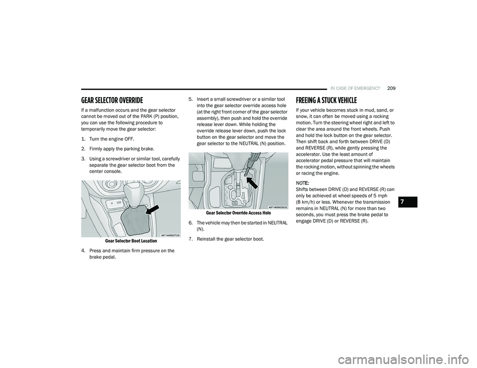
GEAR SELECTOR OVERRIDE
If a malfunction occurs and the gear selector
cannot be moved out of the PARK (P) position,
you can use the following procedure to
temporarily move the gear selector:
1. Turn the engine OFF.
2. Firmly apply the parking brake.
3. Using a screwdriver or similar tool, carefully
separate the gear selector boot from the
center console.
Gear Selector Boot Location
4. Press and maintain firm pressure on the brake pedal. 5. Insert a small screwdriver or a similar tool
into the gear selector override access hole
(at the right front corner of the gear selector
assembly), then push and hold the override
release lever down. While holding the
override release lever down, push the lock
button on the gear selector and move the
gear selector to the NEUTRAL (N) position.
Gear Selector Override Access Hole
6. The vehicle may then be started in NEUTRAL (N).
7. Reinstall the gear selector boot.
FREEING A STUCK VEHICLE
If your vehicle becomes stuck in mud, sand, or
snow, it can often be moved using a rocking
motion. Turn the steering wheel right and left to
clear the area around the front wheels. Push
and hold the lock button on the gear selector.
Then shift back and forth between DRIVE (D)
and REVERSE (R), while gently pressing the
accelerator. Use the least amount of
accelerator pedal pressure that will maintain
the rocking motion, without spinning the wheels
or racing the engine.
NOTE:
Shifts between DRIVE (D) and REVERSE (R) can
only be achieved at wheel speeds of 5 mph
(8 km/h) or less. Whenever the transmission
remains in NEUTRAL (N) for more than two
seconds, you must press the brake pedal to
engage DRIVE (D) or REVERSE (R).
7
21_VM_OM_EN_USC_t.book Page 209
Page 216 of 280
214IN CASE OF EMERGENCY
Replacing Exterior Bulbs
Headlamps
See below steps to replace:
1. Remove the plastic cap from the back of
the headlamp housing.
2. Rotate the bulb counterclockwise.
3. Remove the bulb and replace as needed.
4. Install the bulb and rotate clockwise to lock in place.
5. Reinstall the plastic cap.
Front Turn Signal Lamps
See below steps to replace:
1. Remove the cap from the back of the outer upper headlamp housing.
2. Rotate the bulb counterclockwise and remove.
3. Install the bulb into socket.
4. Rotate the bulb/socket clockwise into the lamp locking it in place.
5. Reinstall the plastic cap.
Parking And Daytime Running Lights
See below steps to replace:
1. Remove the cap from the back of the outer lower headlamp housing.
2. Rotate the bulb counterclockwise and remove.
3. Install the bulb into socket, and rotate bulb/ socket clockwise into lamp locking it in
place.
4. Reinstall the plastic cap.
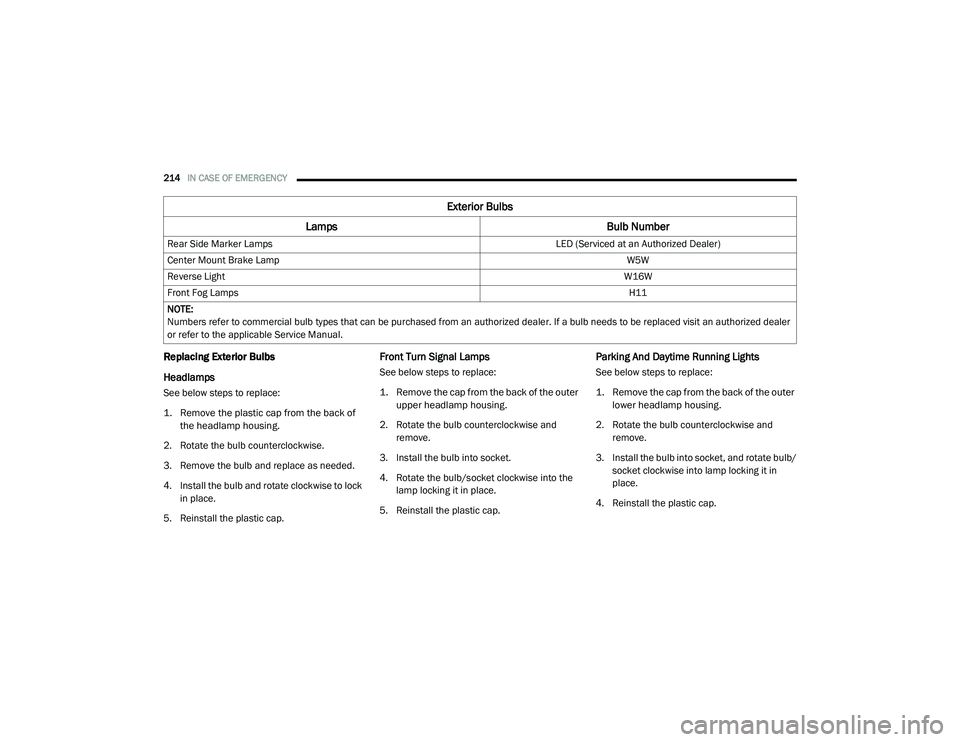
Rear Side Marker Lamps
LED (Serviced at an Authorized Dealer)
Center Mount Brake Lamp W5W
Reverse Light W16W
Front Fog Lamps H11
NOTE:
Numbers refer to commercial bulb types that can be purchased from an authorized dealer. If a bulb needs to be replaced visit an authorized dealer
or refer to the applicable Service Manual.
Exterior Bulbs
Lamps Bulb Number
21_VM_OM_EN_USC_t.book Page 214
Page 221 of 280

SERVICING AND MAINTENANCE219
Mileage or time passed (whichever comes first)
20,000
30,000
40,000
50,000
60,000
70,000
80,000
90,000
100,000
110,000
120,000
130,000
140,000
150,000
Or Years: 2 3 4 5 6 7 8 9 10 11 12 13 14 15
Or Kilometers:
32,000
48,000
64,000
80,000
96,000
112,000
128,000
144,000
160,000
176,000
192,000
208,000
224,000
240,000
Additional Inspections
Inspect the CV/Universal joints. X X X X X X X X X X X X X X
Inspect front suspension, boot seals, tie rod ends, and
replace if necessary. X X X X X
X X
Inspect the brake linings, parking brake function. X X X X XX X
Inspect front accessory drive belt, tensioner, idler pulley, and
replace if necessary. X
Additional Maintenance
Replace engine air cleaner filter.
1X XX XX
Replace air conditioning/cabin air filter. X X X X XX X
Change brake fluid every two years.
2X X X X X X X
Replace spark plugs.
3X
8
21_VM_OM_EN_USC_t.book Page 219