2021 RAM PROMASTER CITY lights
[x] Cancel search: lightsPage 29 of 280

GETTING TO KNOW YOUR VEHICLE27
Sun Visor “Slide-On-Rod” Feature
The sun visor “Slide-On-Rod” feature allows for
additional flexibility in positioning the sun visor
to block out the sun.
1. Fold down the sun visor.
2. Unclip the visor from the corner clip.
3. Pull the sun visor toward the inside rearview
mirror to extend it.
EXTERIOR LIGHTS
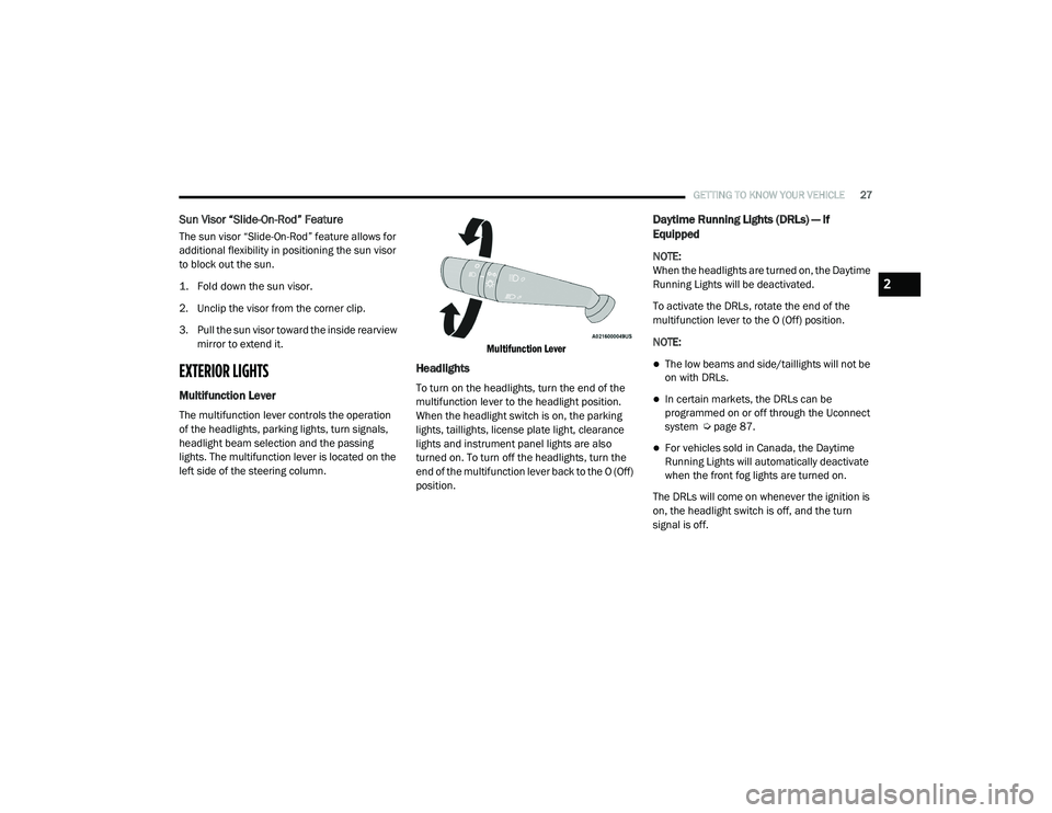
Multifunction Lever
The multifunction lever controls the operation
of the headlights, parking lights, turn signals,
headlight beam selection and the passing
lights. The multifunction lever is located on the
left side of the steering column.
Multifunction Lever
Headlights
To turn on the headlights, turn the end of the
multifunction lever to the headlight position.
When the headlight switch is on, the parking
lights, taillights, license plate light, clearance
lights and instrument panel lights are also
turned on. To turn off the headlights, turn the
end of the multifunction lever back to the O (Off)
position.
Daytime Running Lights (DRLs) — If
Equipped
NOTE:
When the headlights are turned on, the Daytime
Running Lights will be deactivated.
To activate the DRLs, rotate the end of the
multifunction lever to the O (Off) position.
NOTE:
The low beams and side/taillights will not be
on with DRLs.
In certain markets, the DRLs can be
programmed on or off through the Uconnect
system Ú
page 87.
For vehicles sold in Canada, the Daytime
Running Lights will automatically deactivate
when the front fog lights are turned on.
The DRLs will come on whenever the ignition is
on, the headlight switch is off, and the turn
signal is off.
2
21_VM_OM_EN_USC_t.book Page 27
Page 30 of 280

28GETTING TO KNOW YOUR VEHICLE
High/Low Beam Switch
Pull the multifunction lever toward the steering
wheel to switch the headlights to high beams.
Pull the multifunction lever again to turn the low
beams back on.
Flash-To-Pass
You can signal another vehicle with your
headlights by lightly pulling the multifunction
lever toward you. This will cause the high beam
headlights to turn on, and remain on, until the
lever is released.
Parking Lights
These lights can only be turned on with the
ignition in the STOP (OFF/LOCK) position or
removed. Move the end of the multifunction
lever to O (Off) position, and then to the
headlight position.
The indicator light telltale in the instrument
panel comes on. The lights stay on until the next
ignition cycle is performed.
Follow Me Home/Headlight Delay
When this feature is selected, the driver can
choose to have the headlights remain on for a
preset period of time after the engine is turned
off.
Activation
Remove the key or turn the ignition to the STOP
(OFF/LOCK) position, and pull the multifunction
lever toward the steering wheel within two
minutes. Each time the lever is pulled, the
activation of the lights will be extended by
30 seconds. The activation of the lights can be
extended to a maximum of 210 seconds.
Deactivation
Pull the multifunction lever toward the steering
wheel and hold it for more than two seconds.
Fog Lights — If Equipped
The fog light switch is located on the center
stack of the instrument panel, just above the
climate controls. Push the switch once to turn the fog
lights on. Push the switch a second
time to turn the fog lights off.
NOTE:
If the vehicle’s ignition is turned off, the fog
lights will also turn off.
Turn Signals
Move the multifunction lever up or down to
activate the turn signals. The arrows on each
side of the instrument cluster flash to show
proper operation.
NOTE:
If either light remains on and does not flash, or
there is a very fast flash rate, check for a defec -
tive outside light bulb.
Lane Change Assist
Lightly push the multifunction lever up or down,
without moving beyond the detent, and the turn
signal will flash five times then automatically
turn off.
21_VM_OM_EN_USC_t.book Page 28
Page 31 of 280

GETTING TO KNOW YOUR VEHICLE29
INTERIOR LIGHTS
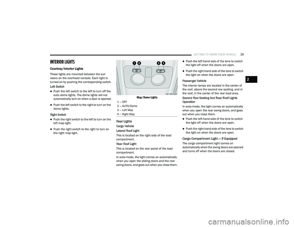
Courtesy/Interior Lights
These lights are mounted between the sun
visors on the overhead console. Each light is
turned on by pushing the corresponding switch.
Left Switch
Push the left switch to the left to turn off the
auto dome lights. The dome lights will not
automatically turn on when a door is opened.
Push the left switch to the right to turn on the
dome lights.
Right Switch
Push the right switch to the left to turn on the
left map light.
Push the right switch to the right to turn on
the right map light.
Map/Dome Lights
Rear Lights
Cargo Vehicle
Lateral Roof Light
This is located on the right side of the load
compartment.
Rear Roof Light
This is located on the rear panel of the load
compartment.
In auto-mode, the light comes on automatically
when you open the sliding doors and the rear
swing doors, and goes out when you close them.
Push the left-hand side of the lens to switch
the light off when the doors are open.
Push the right-hand side of the lens to switch
the light on when the doors are open.
Passenger Vehicle
The interior lamps are located in the center of
the roof, above the second row seating, and in
the roof, in the center of the rear load area.
Second Row Seating And Rear Roof Lights
Operation
In auto-mode, the light comes on automatically
when you open the rear swing doors, and goes
out when you close them.
Push the left-hand side of the lens to switch
the light off when the doors are open.
Push the right-hand side of the lens to switch
the light on when the doors are open.
Cargo Compartment Light — If Equipped
The cargo compartment light comes on
automatically when the swing doors are opened
and turns off when the doors are closed.
1 — OFF
2 — AUTO/Dome
3 — Left Map
4 — Right Map
2
21_VM_OM_EN_USC_t.book Page 29
Page 43 of 280

GETTING TO KNOW YOUR VEHICLE41
(Continued)
(Continued)
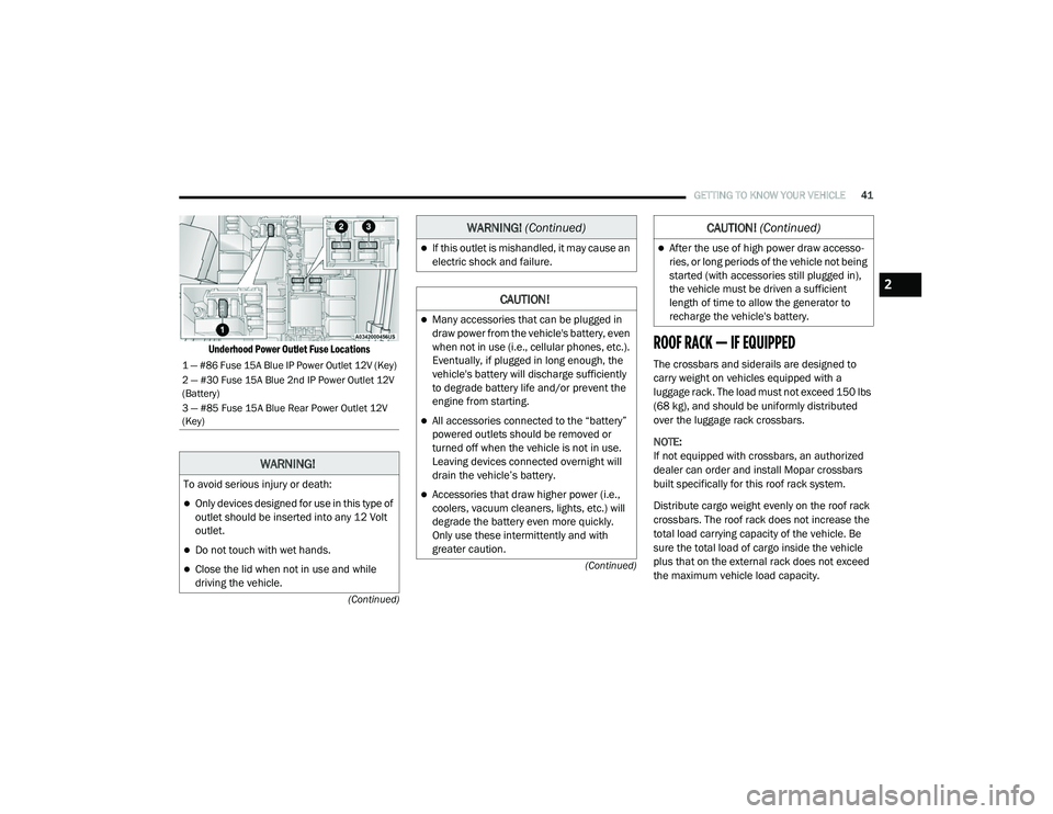
Underhood Power Outlet Fuse Locations
ROOF RACK — IF EQUIPPED
The crossbars and siderails are designed to
carry weight on vehicles equipped with a
luggage rack. The load must not exceed 150 lbs
(68 kg), and should be uniformly distributed
over the luggage rack crossbars.
NOTE:
If not equipped with crossbars, an authorized
dealer can order and install Mopar crossbars
built specifically for this roof rack system.
Distribute cargo weight evenly on the roof rack
crossbars. The roof rack does not increase the
total load carrying capacity of the vehicle. Be
sure the total load of cargo inside the vehicle
plus that on the external rack does not exceed
the maximum vehicle load capacity.1 — #86 Fuse 15A Blue IP Power Outlet 12V (Key)
2 — #30 Fuse 15A Blue 2nd IP Power Outlet 12V
(Battery)
3 — #85 Fuse 15A Blue Rear Power Outlet 12V
(Key)
WARNING!
To avoid serious injury or death:
Only devices designed for use in this type of
outlet should be inserted into any 12 Volt
outlet.
Do not touch with wet hands.
Close the lid when not in use and while
driving the vehicle.
If this outlet is mishandled, it may cause an
electric shock and failure.
CAUTION!
Many accessories that can be plugged in
draw power from the vehicle's battery, even
when not in use (i.e., cellular phones, etc.).
Eventually, if plugged in long enough, the
vehicle's battery will discharge sufficiently
to degrade battery life and/or prevent the
engine from starting.
All accessories connected to the “battery”
powered outlets should be removed or
turned off when the vehicle is not in use.
Leaving devices connected overnight will
drain the vehicle’s battery.
Accessories that draw higher power (i.e.,
coolers, vacuum cleaners, lights, etc.) will
degrade the battery even more quickly.
Only use these intermittently and with
greater caution.
WARNING! (Continued)
After the use of high power draw accesso -
ries, or long periods of the vehicle not being
started (with accessories still plugged in),
the vehicle must be driven a sufficient
length of time to allow the generator to
recharge the vehicle's battery.
CAUTION! (Continued)
2
21_VM_OM_EN_USC_t.book Page 41
Page 47 of 280

GETTING TO KNOW YOUR INSTRUMENT PANEL45
Location And Controls
The instrument cluster display features a driver
interactive display that is located in the
instrument cluster.
Instrument Cluster Display Location
The menu items described below are an
example of what can be found in the vehicle's
menu:
Dimmer
Speed Beep
Trip A / B (options are selectable through the
steering wheel stalk)
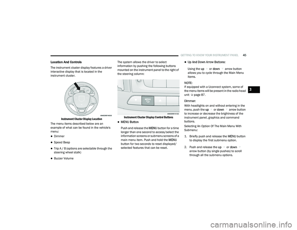
Buzzer Volume The system allows the driver to select
information by pushing the following buttons
mounted on the instrument panel to the right of
the steering column:
Instrument Cluster Display Control Buttons
MENU Button
Push and release the MENU button for a time
longer than one second to access/select the
information screens or submenu screens of a
main menu item. Push and hold the MENU
button for two seconds to reset displayed/
selected features that can be reset.
Up And Down Arrow Buttons:
Using the up or down arrow button
allows you to cycle through the Main Menu
Items.
NOTE:
If equipped with a Uconnect system, some of
the menu items will be present in the radio head
unit Ú page 87.
Dimmer:
With headlights on and without entering in the
menu, push the up or down arrow button
to increase or decrease the brightness of the
instrument panel, graphics and command
buttons.
Selecting An Option Of The Main Menu With
Submenu:
1. Briefly push and release the
MENU
button
to display the first submenu option.
2. Push and release the up or down
arrow button (by single pushes) to scroll
through all the submenu options.
3
21_VM_OM_EN_USC_t.book Page 45
Page 51 of 280

GETTING TO KNOW YOUR INSTRUMENT PANEL49
Values Displayed
Range
This indicates the distance which may be
traveled with the fuel remaining in the tank,
assuming that driving conditions will not
change. The message “----” will appear on the
display in the following cases:
Distance less than 30 miles (or 50 km).
The vehicle is parked for a long time with the
engine running.
NOTE:
The range depends on several factors: driving
style, type of route (freeway, residential, moun -
tain roads, etc.), conditions of use of the vehicle
(load, tire pressure, etc.). Trip planning must
take into account the above notes.
Travel Distance
This value shows the distance covered since the
last reset.
Average Fuel Consumption
This value shows the approximate average
consumption since the last reset.
Current Fuel Consumption
This indicates the fuel consumption. The value
is constantly updated. The message “----” will
appear on the display if the vehicle is parked
with the engine running.
Average Speed
This value shows the vehicle's average speed as
a function of the overall time elapsed since the
last reset.
Travel Time
This value shows the time elapsed since the last
reset.
WARNING LIGHTS AND MESSAGES
The warning/indicator lights will illuminate in
the instrument panel together with a dedicated
message and/or acoustic signal when
applicable. These indications are indicative and
precautionary and as such must not be
considered as exhaustive and/or alternative to
the information contained in the Owner’s
Manual, which you are advised to read carefully
in all cases. Always refer to the information in
this chapter in the event of a failure indication.
All active telltales will display first if applicable.
The system check menu may appear different based upon equipment options and current
vehicle status. Some telltales are optional and
may not appear.
Red Warning Lights
Air Bag Warning Light
This light will turn on for four to eight
seconds as a bulb check when the
ignition is placed in the ON/RUN or
MAR/ON/RUN position. If the light is
either not on during startup, stays on, or turns
on while driving, have the system inspected by
an authorized dealer as soon as possible. This
light will illuminate with a single chime when a
fault with the Air Bag Warning Light has been
detected, it will stay on until the fault is cleared.
If the light comes on intermittently or remains
on while driving, have an authorized dealer
service the vehicle immediately.
Brake Warning Light
This warning light monitors various
brake functions, including brake fluid
level and parking brake application. If
the brake light turns on it may
indicate that the parking brake is applied, that
the brake fluid level is low, or that there is a
problem with the Anti-Lock Brake System
reservoir.
3
21_VM_OM_EN_USC_t.book Page 49
Page 54 of 280

52GETTING TO KNOW YOUR INSTRUMENT PANEL
Seat Belt Reminder Warning Light
When the ignition is first placed in the
ON/RUN or MAR/ON/RUN position, if
the driver’s seat belt is unbuckled, a
chime will sound and the light will turn
on. When driving, if the driver or front passenger
seat belt remains unbuckled, the Seat Belt
Reminder Light will flash or remain on
continuously and a chime will sound
Ú page 153.
Transmission Fault Warning Light
This light will illuminate (together with
a message in the instrument cluster
display and a buzzer) to indicate a
transmission fault. Contact an
authorized dealer if the message remains after
restarting the engine.
Engine Oil Level Warning Light
This warning light appears on the
panel when the engine oil level falls
below the minimum recommended
value. Restore the correct engine oil
level or contact your authorized dealer for
service.
Yellow Warning Lights
Anti-Lock Brake System (ABS) Warning Light
This light monitors the ABS. The light
will turn on when the ignition is placed
in the ON/RUN or MAR/ON/RUN
position and may stay on for as long
as four seconds.
If the ABS light remains on or turns on while
driving, then the Anti-Lock portion of the brake
system is not functioning and service is
required. However, the conventional brake system will continue to operate normally if the
brake warning light is not on.
If the ABS light is on, the brake system should
be serviced as soon as possible to restore the
benefits of Anti-Lock Brakes. If the ABS light
does not turn on when the ignition is placed in
the ON/RUN or MAR/ON/RUN position, have
the light inspected by an authorized dealer.
Low Fuel Warning Light
When the fuel level reaches
approximately 2–3 gal (9–11 L) this
light will turn on, and remain on until
fuel is added.
Generic Warning Light
The Generic Warning Light will
illuminate if any of the following
conditions occur: Engine Oil Pressure
Sensor Failure, External Light Failure,
Parking Sensor Failure, Fuel Cut-Off Fail/
Intervention, Generic Failure on Trailer, or Air
Bag telltale recovery.
The telltale will blink in case of an Air Bag
Warning Light Failure. Contact an authorized
dealer immediately for service.
WARNING!
If you continue operating the vehicle when
the Transmission Temperature Warning Light
is illuminated you could cause the fluid to boil
over, come in contact with hot engine or
exhaust components and cause a fire.
CAUTION!
Continuous driving with the Transmission
Temperature Warning Light illuminated will
eventually cause severe transmission
damage or transmission failure.
21_VM_OM_EN_USC_t.book Page 52
Page 57 of 280

GETTING TO KNOW YOUR INSTRUMENT PANEL55
Electronic Stability Control (ESC) Warning
Light — If Equipped
The ESC Indicator Light in the
instrument cluster will come on when
the ignition is placed in the ON/RUN
or MAR/ON/RUN position, and when
ESC is activated. It should go out with the
engine running. If the ESC Indicator Light comes
on continuously with the engine running, a
malfunction has been detected in the ESC
system. If this light remains on after several
ignition cycles, and the vehicle has been driven
several miles (kilometers) at speeds greater
than 30 mph (48 km/h), see your authorized
dealer as soon as possible to have the problem
diagnosed and corrected.
The ESC OFF Indicator Light and the ESC Indi -
cator Light come on momentarily each time
the ignition is placed in the ON/RUN or MAR/
ON/RUN position.
Each time the ignition is turned to ON/RUN or
MAR/ON/RUN, the ESC system will be on,
even if it was turned off previously.
The ESC system will make buzzing or clicking
sounds when it is active. This is normal; the
sounds will stop when ESC becomes inactive.
This light will come on when the vehicle is in
an ESC event.
Electronic Stability Control (ESC) OFF
Warning Light — If Equipped
This warning light indicates the ESC is
off.
Each time the ignition is turned to ON/RUN or
ACC/ON/RUN, the ESC system will be on, even
if it was turned off previously.
Green Indicator Lights
Turn Signal Indicator Lights
When the left or right turn signal is
activated, the turn signal indicator will
flash independently and the
corresponding exterior turn signal
lamps will flash. Turn signals can be activated
when the multifunction lever is moved down
(left) or up (right). NOTE:
A continuous chime will sound if the vehicle is
driven more than 1 mile (1.6 km) with either
turn signal on.
Check for an inoperative outside light bulb if
either indicator flashes at a rapid rate.
Park/Headlight On Indicator Light
This indicator light will illuminate
when the park lights or headlights are
turned on Ú
page 27.
Front Fog Indicator Light — If Equipped
This indicator light will illuminate
when the front fog lights are on
Úpage 27.
Cruise Control Indicator Light — If Equipped
This indicator light will illuminate
when the cruise control is activated
Úpage 68.
NOTE:
There will be no change in the indicator light
when the desired speed is set.
3
21_VM_OM_EN_USC_t.book Page 55