Page 109 of 176

107
In the event of a breakdown
8
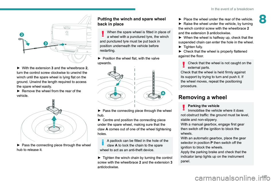
► With the extension 3 and the wheelbrace 2,
turn the control screw clockwise to unwind the
winch until the spare wheel is lying flat on the
ground. Unwind the length required to access
the spare wheel easily.
►
Remove the wheel from the rear of the
vehicle.
► Pass the connecting piece through the wheel
hub to release it.
Putting the winch and spare wheel
back in place
When the spare wheel is fitted in place of
a wheel with a punctured tyre, the winch
and punctured tyre must be put back in
position underneath the vehicle before
restarting.
►
Position the wheel flat, with the valve
upwards.
► Pass the connecting piece through the wheel
hub.
►
Centre and position the connecting piece
under the spare wheel, making sure that the
claw
A comes out of one of the wheel tightening
holes.
A padlock can be fitted in the hole of the claw A to lock the chain to the spare
wheel to act as an anti-theft device.
►
T
ighten the winch chain by turning the control
screw with the wheelbrace 2 and the extension 3
anticlockwise.
► Place the wheel under the rear of the vehicle.
► Raise the wheel under the vehicle, by turning
the winch control screw with the wheelbrace 2
and the extension 3 anticlockwise.
►
When the wheel is halfway up, check that the
suspended
chain can enter the hole in the wheel.
►
T
ighten fully.
►
Check that the wheel is properly flattened
against the floor
.
Check that the wheel is not caught on the
external parts.
Check that the wheel is held firmly against
its support by trying to turn and push it. If
the wheel moves, repeat the positioning
procedure.
Removing a wheel
Parking the vehicle
Immobilise the vehicle where it does
not obstruct traffic: the ground must be level,
stable and non-slippery.
With a manual gearbox, engage first gear
then switch off the ignition to block the
wheels.
With an automatic gearbox, place the gear
selector in position P then switch off the
ignition to block the wheels.
Apply the parking brake and check that the
indicator lamp lights up on the instrument
panel.
Page 114 of 176

11 2
In the event of a breakdown
► Turn the connector a quarter turn
anti-clockwise.
►
Pull the bulb connector
.
►
Remove the bulb and replace it.
Amber-coloured bulbs must be replaced by bulbs with identical specifications and
colour.
Daytime running lamps
► Remove the protective cover by giving it a
quarter turn.
►
Pull the bulb holder backwards to remove it.
►
Pull out the bulb and replace it.
When refitting the bulb holder in its housing,
press until you hear a click which means it is
locked in place.
Rear lamps
1. A: Brake lamps/sidelamps (P21/5W)
or
B: Brake lamps (P21W)
2. Direction indicators (PY21W)
3. Reversing lamps (W16W)
4. Foglamp (P21W)
5. B: Sidelamps
(LED)
►
Open the tailgate.
► Unscrew the 2 fixing screws located on the
pillar .
►
Hold the lamp and unclip it by pulling
outwards then turn it over carefully
.
► Turn the bulb holder a quarter turn
anti-clockwise.
► Remove the bulb holder and replace the
bulb by pulling or pressing then turning the bulb
(depending on the bulb type).
Changing a fuse
Accessing the tools
The extraction tweezers are located in the
fusebox.
Page 115 of 176

11 3
In the event of a breakdown
8
► Turn the bulb holder a quarter turn
anti-clockwise.
►
Remove the bulb holder and replace the
bulb by pulling or pressing then turning the bulb
(depending on the bulb type).
Changing a fuse
Accessing the tools
The extraction tweezers are located in the
fusebox.
► Unclip the first cover by pulling the upper
part, then tilt and remove the cover completely .
►
Unclip the second cover by pressing clip
A
,
then pull the cover to remove it.
►
T
ake the tweezers from their housing.
Changing a fuse
Before changing a fuse:
► Identify the cause of the fault and fix it.
►
Switch off all power consumption.
►
Immobilise the vehicle and switch off the
ignition.
►
Identify the defective fuse using the current
allocation tables and diagrams.
T
o replace a fuse, it is essential to:
►
Use the special tweezers to extract the fuse
from its housing and check the condition of its
filament.
►
Always replace the failed fuse with a fuse of
the same rating (same colour); use of a different
rating may cause malfunctions - risk of fire!
If the fault recurs soon after replacing a fuse,
have the electrical system checked by a
PEUGEOT dealer or a qualified workshop.
The fuse allocation tables and the corresponding diagrams are available
from a PEUGEOT dealer or from a qualified
workshop.
The replacement of a fuse not shown in the allocation tables may cause a serious
malfunction of the vehicle. Contact a
PEUGEOT dealer or a qualified workshop.
Good
Faulty
Tweezers
Installing electrical accessories
The vehicle's electrical system is
designed to operate with standard or optional
equipment.
Before fitting other electrical equipment
or accessories to your vehicle, contact a
PEUGEOT dealer or a qualified workshop.