2021 NISSAN FRONTIER lights
[x] Cancel search: lightsPage 188 of 492
AUTOMATIC ANTI-GLARE
REARVIEW MIRROR
The inside mirror is designed so that it au-
tomatically dims during nighttime condi-
tions and according to the intensity of the
headlights of the vehicle following you. The
automatic anti-glare feature is activated
when the ignition switch is in the ON posi-
tion.
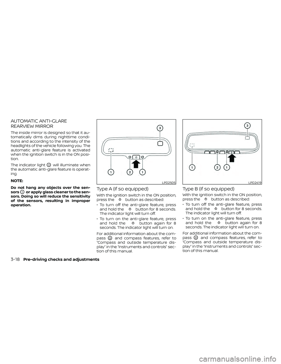
The indicator light
O2will illuminate when
the automatic anti-glare feature is operat-
ing.
NOTE:
Do not hang any objects over the sen-
sors
O1or apply glass cleaner to the sen-
sors. Doing so will reduce the sensitivity
of the sensors, resulting in improper
operation.Type A (if so equipped)
With the ignition switch in the ON position,
press thebutton as described:
• To turn off the anti-glare feature, press and hold the
button for 8 seconds.
The indicator light will turn off.
• To turn on the anti-glare feature, press and hold the
button again for 8
seconds. The indicator light will turn on.
For additional information about the com-
pass
O3and compass features, refer to
“Compass and outside temperature dis-
play” in the “Instruments and controls” sec-
tion of this manual.
Type B (if so equipped)
With the ignition switch in the ON position,
press thebutton as described:
• To turn off the anti-glare feature, press and hold the
button for 8 seconds.
The indicator light will turn off.
• To turn on the anti-glare feature, press and hold the
button again for 8
seconds. The indicator light will turn on.
For additional information about the com-
pass
O3and compass features, refer to
“Compass and outside temperature dis-
play” in the “Instruments and controls” sec-
tion of this manual.
LPD2505LPD2419
3-18Pre-driving checks and adjustments
Page 233 of 492
Static and flutter: During signal interfer-
ence from buildings, large hills or due to
antenna position (usually in conjunction
with increased distance from the station
transmitter), static or flutter can be heard.
This can be reduced by adjusting the treble
control to reduce treble response.
Multipath reception: Because of the reflec-
tive characteristics of FM signals, direct and
reflected signals reach the receiver at the
same time. The signals may cancel each
other, resulting in momentary flutter or loss
of sound.
AM RADIO RECEPTION
AM signals, because of their low frequency,
can bend around objects and skip along
the ground. In addition, the signals can be
bounced off the ionosphere and bent back
to earth. Because of these characteristics,
AM signals are also subject to interference
as they travel from transmitter to receiver.
Fading: Occurs while the vehicle is passing
through freeway underpasses or in areas
with many tall buildings. It can also occur for
several seconds during ionospheric turbu-
lence even in areas where no obstacles exist.
Static: Caused by thunderstorms, electrical
power lines, electric signs and even traffic
lights.
SATELLITE RADIO RECEPTION (if so
equipped)
When the satellite radio is used for the first
time or the battery has been replaced, the
satellite radio may not work properly. This
is not a malfunction. Wait more than 10
minutes with satellite radio ON and the ve-
hicle outside of any metal or large building
for satellite radio to receive all of the neces-
sary data.
No satellite radio reception is available and
“NO SAT” is displayed when the SAT band
option is selected unless optional satellite
receiver and antenna are installed and a
SiriusXM® Satellite Radio service subscrip-
tion is active. Satellite radio is not available
in Alaska, Hawaii and Guam.
Satellite radio performance may be af-
fected if cargo carried on the roof blocks
the satellite radio signal.
If possible, do not put cargo over the satel-
lite antenna.
A build up of ice on the satellite radio an-
tenna can affect satellite radio perfor-
mance. Remove the ice to restore satellite
radio reception.
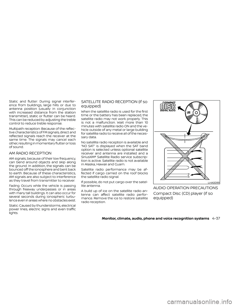
AUDIO OPERATION PRECAUTIONS
Compact Disc (CD) player (if so
equipped)
LHA0099
Page 318 of 492
•Always use tires of the same type,
size, brand, construction (bias, bias-
belted, or radial), and tread pattern
on all four wheels. Install tire chains
on the rear wheels when driving on
slippery roads and drive carefully.
• Be sure to check the brakes immedi-
ately af ter driving in mud or water.
For additional information, refer to
“Wet brakes” in this section.
• Avoid parking your vehicle on steep
hills. If you get out of the vehicle and
it rolls forward, backward or side-
ways, you could be injured.
• Whenever you drive off-road through
sand, mud or water as deep as the
wheel hub, more frequent mainte-
nance may be required. For addi-
tional information, refer to “Mainte-
nance under severe operating
conditions” in the “Maintenance and
schedules” section of this manual.
WARNING
Do not operate the push-button igni-
tion switch while driving the vehicle ex-
cept in an emergency. (The engine will
stop when the ignition switch is pushed
three consecutive times in quick suc-
cession or the ignition switch is pushed
and held for more than 2 seconds.) If
the engine stops while the vehicle is
being driven, this could lead to a crash
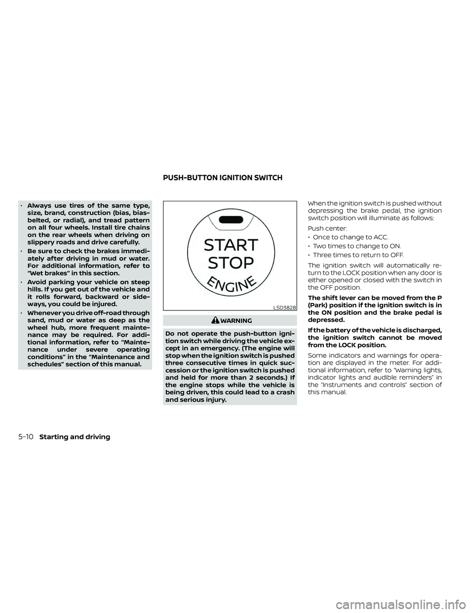
and serious injury. When the ignition switch is pushed without
depressing the brake pedal, the ignition
switch position will illuminate as follows:
Push center:
• Once to change to ACC.
• Two times to change to ON.
• Three times to return to OFF.
The ignition switch will automatically re-
turn to the LOCK position when any door is
either opened or closed with the switch in
the OFF position.
The shif t lever can be moved from the P
(Park) position if the ignition switch is in
the ON position and the brake pedal is
depressed.
If the battery of the vehicle is discharged,
the ignition switch cannot be moved
from the LOCK position.
Some indicators and warnings for opera-
tion are displayed in the meter. For addi-
tional information, refer to “Warning lights,
indicator lights and audible reminders” in
the “Instruments and controls” section of
this manual.
LSD3828
PUSH-BUTTON IGNITION SWITCH
Page 321 of 492
NISSAN VEHICLE IMMOBILIZER
SYSTEM
The NISSAN Vehicle Immobilizer System
will not allow the engine to start without
the use of the registered key.
If the engine fails to start using a registered
key (for example, when interference is
caused by another registered key, an auto-
mated toll road device or automatic pay-
ment device on the key ring), restart the
engine using the following procedures:
1. Leave the ignition switch in the ON posi-tion for approximately 5 seconds.
2. Place the ignition switch in the OFF or LOCK position, and wait approximately
10 seconds.
3. Repeat steps 1 and 2.
4. Restart the engine while holding the de- vice (which may have caused the inter-
ference) separate from the registered
key.
If the no start condition re-occurs, NISSAN
recommends placing the registered key on
a separate key ring to avoid interference
from other devices. • Make sure the area around the vehicle is
clear.
• Check fluid levels such as engine oil, cool- ant, brake, and windshield-washer fluid
as frequently as possible, or at least
whenever you refuel.
• Check that all windows and lights are clean.
• Visually inspect tires for their appearance and condition. Also check tires for proper
inflation.
• Check that all doors are closed.
• Position seat and adjust head restraints/ headrests.
• Adjust inside and outside mirrors.
• Fasten the seat belt and ask all passen- gers to do likewise.
• Check the operation of warning lights when the ignition switch is placed in the
ON position. For additional information,
refer to “Warning lights, indicator lights
and audible reminders” in the “Instru-
ments and controls” section of this
manual. 1. Apply the parking brake.
2. Move the shif t lever to P (Park) or N (Neu-
tral). P (Park) is recommended.
The starter is designed not to operate
unless the shif t lever is in either P
(Park) or N (Neutral).
3. Push the ignition switch to the ON posi- tion. Depress the brake pedal and push
the ignition switch to start the engine.
To start the engine immediately, push
and release the ignition switch while de-
pressing the brake pedal with the igni-
tion switch in any position.
• If the engine is very hard to start in extremely cold weather or when re-
starting, depress the accelerator
pedal a little (approximately 1/3 to the
floor) and while holding, crank the en-
gine. Release the accelerator pedal
when the engine starts.
• If the engine is very hard to start be- cause it is flooded, depress the accel-
erator pedal all the way to the floor
and hold it. Push the ignition switch to
the ON position to start cranking the
engine. Af ter 5 or 6 seconds, stop
cranking by pushing the ignition
switch to the LOCK position. Af ter
BEFORE STARTING THE ENGINE STARTING THE ENGINE
Starting and driving5-13
Page 333 of 492
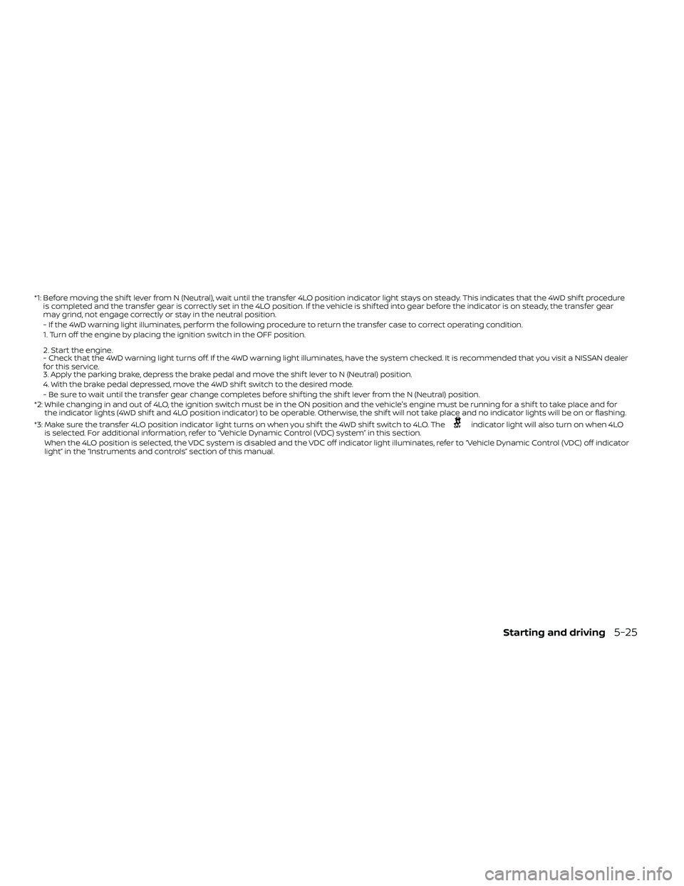
*1: Before moving the shif t lever from N (Neutral), wait until the transfer 4LO position indicator light stays on steady. This indicates that the 4WD shif t procedure
is completed and the transfer gear is correctly set in the 4LO position. If the vehicle is shif ted into gear before the indicator is on steady, the transf er gear
may grind, not engage correctly or stay in the neutral position.
- If the 4WD warning light illuminates, perform the following procedure to return the transfer case to correct operating condition.
1. Turn off the engine by placing the ignition switch in the OFF position.
2. Start the engine.
- Check that the 4WD warning light turns off. If the 4WD warning light illuminates, have the system checked. It is recommended that you visit a NISSAN dea ler
for this service.
3. Apply the parking brake, depress the brake pedal and move the shif t lever to N (Neutral) position.
4. With the brake pedal depressed, move the 4WD shif t switch to the desired mode.
- Be sure to wait until the transfer gear change completes before shif ting the shif t lever from the N (Neutral) position.
*2: While changing in and out of 4LO, the ignition switch must be in the ON position and the vehicle's engine must be running for a shif t to take place and for the indicator lights (4WD shif t and 4LO position indicator) to be operable. Otherwise, the shif t will not take place and no indicator lights will be on o r flashing.
*3: Make sure the transfer 4LO position indicator light turns on when you shif t the 4WD shif t switch to 4LO. The
indicator light will also turn on when 4LO
is selected. For additional information, refer to “Vehicle Dynamic Control (VDC) system” in this section.
When the 4LO position is selected, the VDC system is disabled and the VDC off indicator light illuminates, refer to “Vehicle Dynamic Control (VDC) off indicator
light” in the “Instruments and controls” section of this manual.
Starting and driving5-25
Page 343 of 492
The VDC system uses various sensors to
monitor driver inputs and vehicle motion.
Under certain driving conditions, the VDC
system helps to perform the following
functions:
• Controls brake pressure to reduce wheelslip on one slipping drive wheel so power
is transferred to a non-slipping drive
wheel on the same axle.
• Controls brake pressure and engine out- put to reduce drive wheel slip based on
vehicle speed (traction control function).
• If the 4WD transfer case is shif ted into 4LO the
indicator light will come on and
the VDC system will be turned off. For
additional information, refer to “Using
4–Wheel Drive (4WD)” in this section.
• Controls brake pressure at individual wheels and engine output to help the
driver maintain control of the vehicle in
the following conditions:– Understeer (vehicle tends to not follow the steered path despite increased
steering input)
– Oversteer (vehicle tends to spin due to certain road or driving conditions)
The VDC system can help the driver to
maintain control of the vehicle, but it can-
not prevent loss of vehicle control in all driv-
ing situations. When the VDC system operates, the
indicator light in the instrument panel
flashes so note the following:
• The road may be slippery or the system
may determine some action is required
to help keep the vehicle on the steered
path.
• You may feel a pulsation in the brake pedal and hear a noise or vibration from
under the hood. This is normal and indi-
cates that the VDC system is working
properly.
• Adjust your speed and driving to the road conditions.
For additional information, refer to “Slip in-
dicator light” and ”Vehicle Dynamic Control
(VDC) OFF indicator light” in the ”Instru-
ments and controls” section of this manual.
If a malfunction occurs in the system, the
indicator light will come on in the in-
strument panel. The VDC system auto-
matically turns off when these indicator
lights are off.
The VDC OFF switch is used to turn off the
VDC system. The
indicator light illumi-
nates to indicate the VDC system is off. When the VDC OFF switch is used to turn off
the system, the VDC system still operates
to prevent one drive wheel from slipping by
transferring power to a non-slipping drive
wheel. The
indicator light flashes if this
occurs. All other VDC functions are off and
the
indicator light will not flash.
The VDC system is automatically reset to
on when the ignition switch is placed in the
OFF position then back to the ON position.
The computer has a built-in diagnostic fea-
ture that tests the system each time you
start the engine and move the vehicle for-
ward or in reverse at a slow speed. When
the self-test occurs, you may hear a clunk
noise and/or feel a pulsation in the brake
pedal. This is normal and is not an indica-
tion of a malfunction.
VEHICLE DYNAMIC CONTROL (VDC)
SYSTEM
Starting and driving5-35
Page 344 of 492

WARNING
• The VDC system is designed to help
the driver maintain stability but does
not prevent accidents due to abrupt
steering operation at high speeds or
by careless or dangerous driving
techniques. Reduce vehicle speed
and be especially careful when driv-
ing and cornering on slippery sur-
faces and always drive carefully.
• Do not modif y the vehicle's suspen-
sion. If suspension parts such as
shock absorbers, struts, springs, sta-
bilizer bars, bushings and wheels are
not NISSAN recommended for your
vehicle or are extremely deterio-
rated, the VDC system may not oper-
ate properly. This could adversely af-
fect vehicle handling performance,
and the
indicator light may flash
or theindicator light may
illuminate.
• If brake related parts such as brake
pads, rotors and calipers are not
NISSAN recommended or are ex-
tremely deteriorated, the VDC sys-
tem may not operate properly and
both the
andindicator
lights may illuminate. •
If engine control related parts are not
NISSAN recommended or are ex-
tremely deteriorated, both the
andindicator lights may
illuminate.
• When driving on extremely inclined
surfaces such as higher banked cor-
ners, the VDC system may not oper-
ate properly and the
indicator
light may flash or theindicator
light may illuminate. Do not drive on
these types of roads.
• When driving on an unstable surface
such as a turntable, ferry, elevator or
ramp, the
indicator light may
flash or theindicator light may
illuminate. This is not a malfunction.
Restart the engine af ter driving onto
a stable surface.
• If wheels or tires other than the
NISSAN recommended ones are
used, the VDC system may not oper-
ate properly and the
indicator
light may flash or theindicator
light may illuminate.
• The VDC system is not a substitute
for winter tires or tire chains on a
snow covered road.
BRAKE FORCE DISTRIBUTION
During braking while driving through turns,
the system optimizes the distribution of
force to each of the four wheels depending
on the radius of the turn.
indicator light may flash
or theindicator light may
illuminate.
5-36Starting and driving
Page 345 of 492
•If brake related parts such as brake
pads, rotors and calipers are not
NISSAN recommended or are ex-
tremely deteriorated, the VDC sys-
tem may not operate properly and
both the
and theindicator
lights may illuminate.
• If engine control related parts are not
NISSAN recommended or are ex-
tremely deteriorated, both the
andindicator lights may
illuminate.
• When driving on extremely inclined
surfaces such as higher banked cor-
ners, the VDC system may not oper-
ate properly and the
indicator
light may flash or theindicator
light may illuminate. Do not drive on
these types of roads.
• When driving on an unstable surface
such as a turntable, ferry, elevator or
ramp, the
indicator light may
flash or theindicator light may
illuminate. This is not a malfunction.
Restart the engine af ter driving onto
a stable surface. •
If wheels or tires other than the
NISSAN recommended ones are
used, the VDC system may not oper-
ate properly and the
indicator
light may flash or theindicator
light may illuminate.
• The VDC system is not a substitute
for winter tires or tire chains on a
snow covered road.
WARNING
• Never rely solely on the hill descent
control system to control vehicle
speed when driving on steep down-
hill grades. Always drive carefully and
attentively when using the hill de-
scent control system and decelerate
the vehicle speed by depressing the
brake pedal if necessary. Be espe-
cially careful when driving on frozen,
muddy or extremely steep downhill
roads. Failure to control vehicle
speed may result in a loss of control
of the vehicle and possible serious
injury or death.
• The hill descent control may not con-
trol the vehicle speed on a hill under
all load or road conditions. Always be
prepared to depress the brake pedal
to control vehicle speed. Failure to do
so may result in a collision or serious
personal injury.
The hill descent control system helps
maintain vehicle speed when driving under
15-21 mph (25-35 km/h) on steeper down-
hill grades. Hill descent control is useful
when engine braking alone in 4H or 4L can-
not control vehicle speed. Hill descent con-
trol applies the vehicle brakes to control
HILL DESCENT CONTROL SYSTEM (if
so equipped)
Starting and driving5-37