2021 NISSAN FRONTIER instrument panel
[x] Cancel search: instrument panelPage 231 of 492
MANUAL OPERATION
Fan speed control
Turn thefan speed control dial to
manually control the fan speed.
Press the AUTO button to return to auto-
matic control of the fan speed.
Air recirculation
Press the air recirculation buttonto
recirculate interior air inside the vehicle.
Press the AUTO button to return to auto-
matic mode.
The air recirculation cannot be activated
when the air conditioner is in the
front
defogging mode.
Fresh air intake (if so equipped)
Press thefresh air intake button to
draw outside air into the passenger com-
partment. The
indicator light on the
button will come on.
A/C (air conditioner) button
Start the engine, turn thefan speed
control dial to the desired position and
press the
button to turn on the air
conditioner. To turn off the air conditioner,
press the
button again. The air conditioner cooling function op-
erates only when the engine is running.
Air flow control
Press the air flow control buttons to manu-
ally control air flow and select the air outlet:
— Air flows from center and side
vents.
— Air flows from center and sidevents and foot outlets.
— Air flows mainly from foot outlets.— Air flows from defroster and footoutlets.
— Air flows from defroster outlets.
To turn system off
Press the OFF button.
Rear window or outside mirror
defroster switch (if so equipped)
For additional information, refer to “Rear
window or outside mirror defroster switch”
in the “Instruments and controls” section of
this manual.
OPERATING TIPS
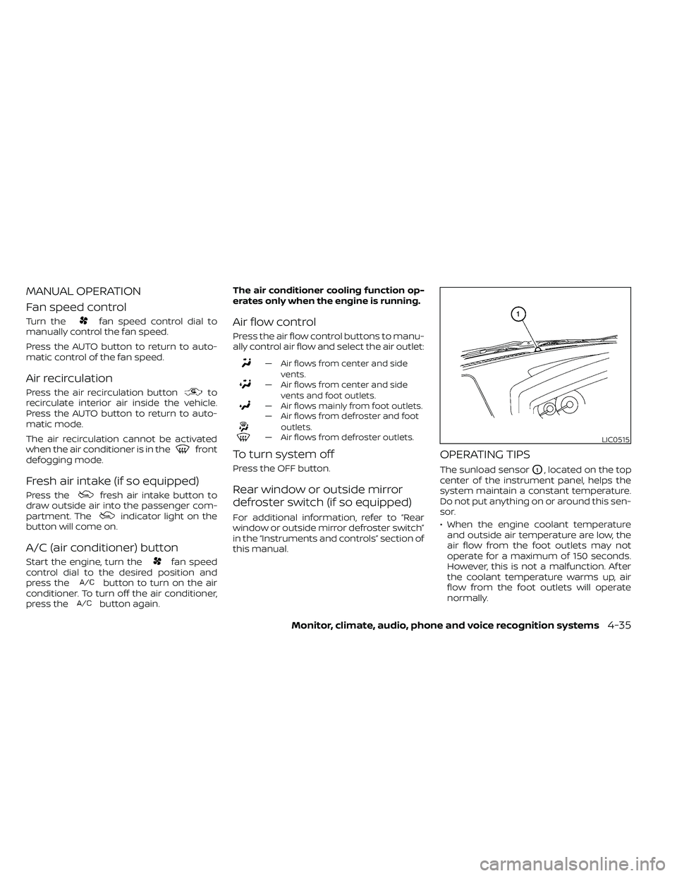
The sunload sensorO1, located on the top
center of the instrument panel, helps the
system maintain a constant temperature.
Do not put anything on or around this sen-
sor.
• When the engine coolant temperature and outside air temperature are low, the
air flow from the foot outlets may not
operate for a maximum of 150 seconds.
However, this is not a malfunction. Af ter
the coolant temperature warms up, air
flow from the foot outlets will operate
normally.
LIC0515
Page 255 of 492
CAUTION
• Do not force the USB device into the
USB port. Inserting the USB device
tilted or up-side-down into the port
may damage the port. Make sure
that the USB device is connected cor-
rectly into the USB port.
• Do not grab the USB port cover (if so
equipped) when pulling the USB de-
vice out of the port. This could dam-
age the port and the cover.
• Do not leave the USB cable in a place
where it can be pulled unintention-
ally. Pulling the cable may damage
the port.
For additional information, refer to your de-
vice manufacturer’s owner information re-
garding the proper use and care of the
device.
The USB port is located on the instrument
panel. Insert the USB device into the instru-
ment panel.
When a compatible storage device is
plugged into the connection port, compat-
ible audio files on the storage device can be
played through the vehicle's audio system.Audio file operation
AUX (auxiliary) button
Place the ignition switch in the ON or ACC
position and press the AUX button to
switch to the USB input mode. If another
audio source is playing and a USB connec-
tion port device is inserted, press the AUX
button until the center display changes to
the USB memory mode.
If the system has been turned off while the
USB memory was playing, press the ON-
OFF button to restart the USB memory.
Play information
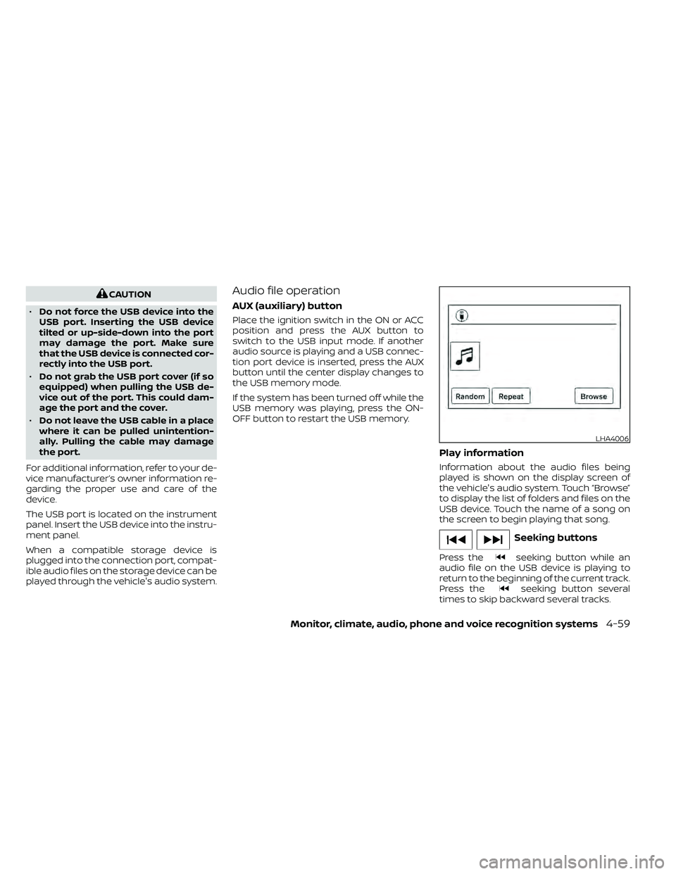
Information about the audio files being
played is shown on the display screen of
the vehicle's audio system. Touch “Browse”
to display the list of folders and files on the
USB device. Touch the name of a song on
the screen to begin playing that song.
seeking button while an
audio file on the USB device is playing to
return to the beginning of the current track.
Press the
seeking button several
times to skip backward several tracks.
LHA4006
Page 260 of 492
CAUTION
• Do not force the USB device into the
USB port. Inserting the USB device
tilted or up-side-down into the port
may damage the port. Make sure
that the USB device is connected cor-
rectly into the USB port.
• Do not grab the USB port cover (if so
equipped) when pulling the USB de-
vice out of the port. This could dam-
age the port and the cover.
• Do not leave the USB cable in a place
where it can be pulled unintention-
ally. Pulling the cable may damage
the port.
For additional information, refer to your de-
vice manufacturer’s owner information re-
garding the proper use and care of the
device.
To connect an iPod® to the vehicle so that
the iPod® can be controlled with the audio
system controls and display screen, use
the USB port located on the instrument
panel. Connect the iPod®-specific end of
the cable to the iPod® and the USB end of
the cable to the USB port on the vehicle. If
your iPod® supports charging via a USB
connection, its battery will be charged while connected to the vehicle with the ig-
nition switch in the ACC or ON position.
While connected to the vehicle, the iPod®
can only be operated by the vehicle audio
controls.
To disconnect the iPod® from the vehicle,
remove the USB end of the cable from the
USB port on the vehicle, then remove the
cable from the iPod®.
* iPod® is a trademark of Apple Inc., regis-
tered in the U.S. and other countries.
Compatibility
The following models are compatible:
• iPod® Classic 5th generation (firmware
version 1.3.0 or later)
• iPod® Classic 6th generation (firmware version 2.0.1 or later)
• iPod® Classic 7th generation (firmware version 2.0.4 or later)
• iPod® Touch 2nd generation (firmware version 4.2.1 or later)*
• iPod® Touch 3rd generation (firmware version 5.1 or later)
• iPod® Touch 4th generation (firmware version 5.1 or later)
• iPod® nano - 1st generation (firmware version 1.3.1 or later) • iPod® nano - 2nd generation (firmware
version 1.1.3 or later)
• iPod® nano - 3rd generation (firmware version 1.1.3 or later)
• iPod® nano - 4th generation (firmware version 1.0.4 or later)
• iPod® nano - 5th generation (firmware version 1.0.2 or later)
• iPod® nano - 6th generation (firmware version 1.1 or later)
• iPhone® 3G (firmware version 4.2.1 or later)
• iPhone® 3GS (firmware version 5.1 or later)
• iPhone® 4 (firmware version 5.1 or later)
• iPhone® 4S (firmware version 5.1 or later)
* Some features of this iPod® may not be
fully functional.
Make sure that your iPod® firmware is up-
dated to the version indicated above.
4-64Monitor, climate, audio, phone and voice recognition systems
Page 327 of 492
WARNING
• Be sure the parking brake is fully re-
leased before driving. Failure to do so
can cause brake failure and lead to
an accident.
• Do not release the parking brake
from outside the vehicle.
• Do not use the shif t lever in place of
the parking brake. When parking, be
sure the parking brake is fully
engaged.
• To help avoid risk of injury or death
through unintended operation of the
vehicle and/or its systems, do not
leave children, people who require
the assistance of others or pets unat-
tended in your vehicle. Additionally,
the temperature inside a closed ve-
hicle on a warm day can quickly be-
come high enough to cause a signifi-
cant risk of injury or death to people
and pets. To engage:
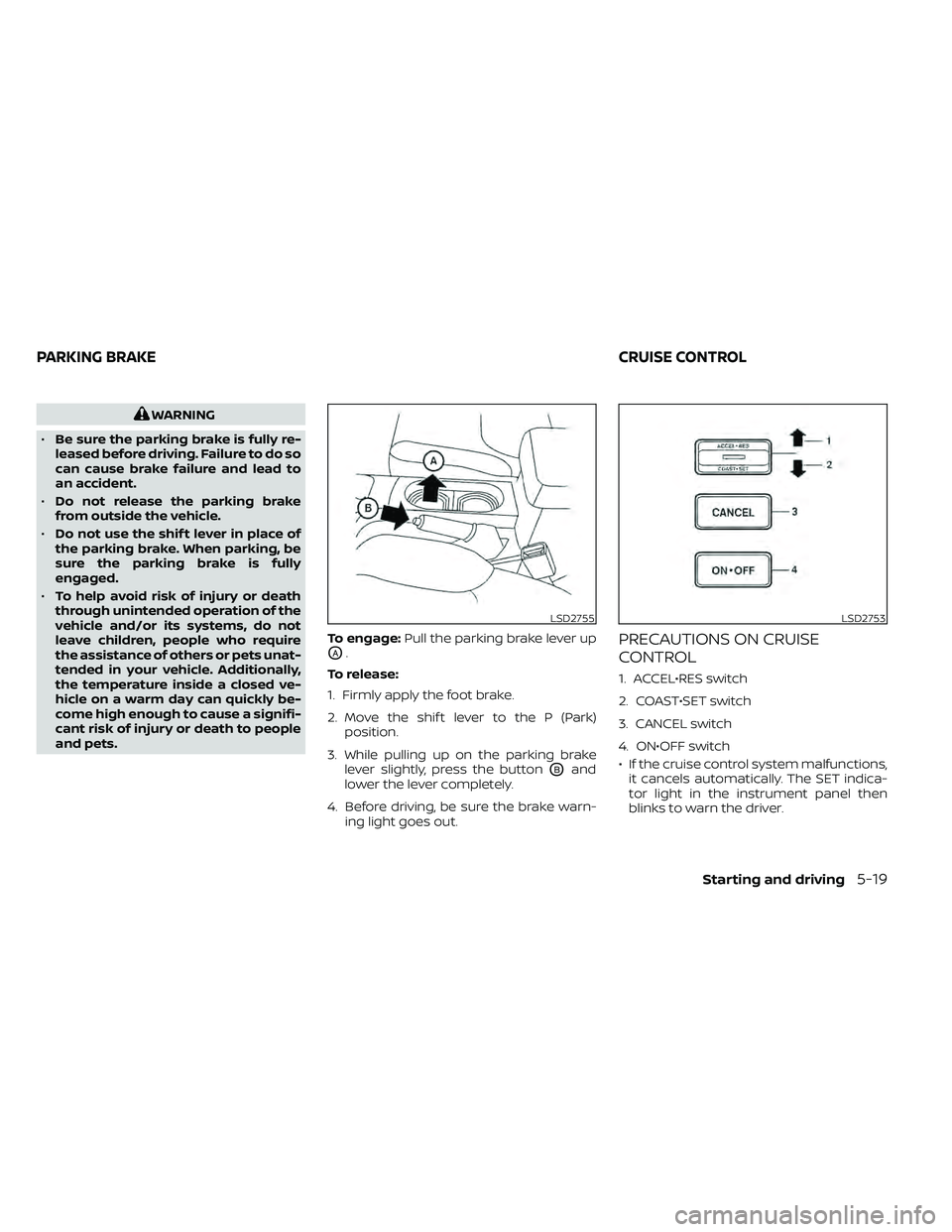
Pull the parking brake lever up
OA.
To release:
1. Firmly apply the foot brake.
2. Move the shif t lever to the P (Park) position.
3. While pulling up on the parking brake lever slightly, press the button
OBand
lower the lever completely.
4. Before driving, be sure the brake warn- ing light goes out.
PRECAUTIONS ON CRUISE
CONTROL
1. ACCEL•RES switch
2. COAST•SET switch
3. CANCEL switch
4. ON•OFF switch
• If the cruise control system malfunctions,it cancels automatically. The SET indica-
tor light in the instrument panel then
blinks to warn the driver.
LSD2755LSD2753
PARKING BRAKE CRUISE CONTROL
Starting and driving5-19
Page 343 of 492
The VDC system uses various sensors to
monitor driver inputs and vehicle motion.
Under certain driving conditions, the VDC
system helps to perform the following
functions:
• Controls brake pressure to reduce wheelslip on one slipping drive wheel so power
is transferred to a non-slipping drive
wheel on the same axle.
• Controls brake pressure and engine out- put to reduce drive wheel slip based on
vehicle speed (traction control function).
• If the 4WD transfer case is shif ted into 4LO the
indicator light will come on and
the VDC system will be turned off. For
additional information, refer to “Using
4–Wheel Drive (4WD)” in this section.
• Controls brake pressure at individual wheels and engine output to help the
driver maintain control of the vehicle in
the following conditions:– Understeer (vehicle tends to not follow the steered path despite increased
steering input)
– Oversteer (vehicle tends to spin due to certain road or driving conditions)
The VDC system can help the driver to
maintain control of the vehicle, but it can-
not prevent loss of vehicle control in all driv-
ing situations. When the VDC system operates, the
indicator light in the instrument panel
flashes so note the following:
• The road may be slippery or the system
may determine some action is required
to help keep the vehicle on the steered
path.
• You may feel a pulsation in the brake pedal and hear a noise or vibration from
under the hood. This is normal and indi-
cates that the VDC system is working
properly.
• Adjust your speed and driving to the road conditions.
For additional information, refer to “Slip in-
dicator light” and ”Vehicle Dynamic Control
(VDC) OFF indicator light” in the ”Instru-
ments and controls” section of this manual.
If a malfunction occurs in the system, the
indicator light will come on in the in-
strument panel. The VDC system auto-
matically turns off when these indicator
lights are off.
The VDC OFF switch is used to turn off the
VDC system. The
indicator light illumi-
nates to indicate the VDC system is off. When the VDC OFF switch is used to turn off
the system, the VDC system still operates
to prevent one drive wheel from slipping by
transferring power to a non-slipping drive
wheel. The
indicator light flashes if this
occurs. All other VDC functions are off and
the
indicator light will not flash.
The VDC system is automatically reset to
on when the ignition switch is placed in the
OFF position then back to the ON position.
The computer has a built-in diagnostic fea-
ture that tests the system each time you
start the engine and move the vehicle for-
ward or in reverse at a slow speed. When
the self-test occurs, you may hear a clunk
noise and/or feel a pulsation in the brake
pedal. This is normal and is not an indica-
tion of a malfunction.
VEHICLE DYNAMIC CONTROL (VDC)
SYSTEM
Starting and driving5-35
Page 346 of 492
vehicle speed allowing the driver to con-
centrate on steering while reducing the
burden of brake and accelerator operation.
• When additional braking is required onsteep downhill roads, activate the hill de-
scent control system by pushing the
switch on. For additional information, re-
fer to “Hill descent control switch” in the
“Instruments and controls” section of this
manual.
• Once the system is activated, the indica- tor light will remain on in the instrument
panel. For additional information, refer to
“Hill descent control system ON indicator
light” in the “Instruments and controls”
section of this manual.
If the accelerator or brake pedal is de-
pressed while the hill descent control sys-
tem is on, the system will stop operating
temporarily. As soon as the accelerator or
brake pedal is released, the hill descent
control system begins to function again if
the hill descent control operating condi-
tions are fulfilled.
For the best results, when descending
steep downhill grades, the hill descent con-
trol switch should be on and the shif t lever
in 2 (Second gear) or 1 (Low gear) for engine
braking.
Page 347 of 492
WARNING
• Always turn and look back before
backing up. The RSS is not a substi-
tute for proper backing procedures.
• Read and understand the limitations
of the RSS as contained in this sec-
tion. Inclement weather may affect
the function of the RSS; this may in-
clude reduced performance or a false
activation.
• This system is not designed to pre-
vent contact with small or moving
objects. •
The system is designed as an aid to
the driver in detecting large station-
ary objects to help avoid damaging
the vehicle. The system will not de-
tect small objects below the bumper,
and may not detect objects close to
the bumper or on the ground.
• If your vehicle sustains damage to
the rear bumper fascia, leaving it
misaligned or bent, the sensing zone
may be altered causing inaccurate
measurement of obstacles or false
alarms.
The RSS sounds a tone to warn the driver of
obstacles near the rear bumper when the
shif t lever is in R (Reverse). The system may
not detect objects at speeds above 3 mph
(5 km/h) and may not detect certain angu-
lar or moving objects.
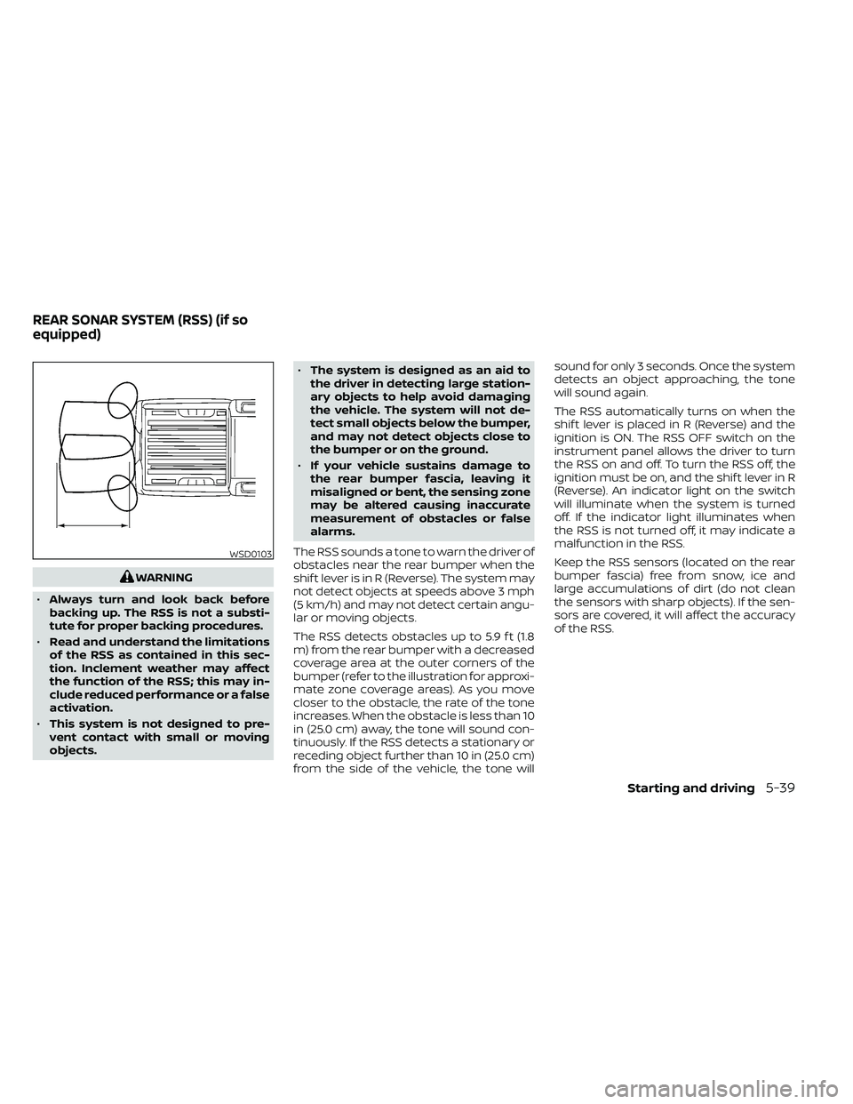
The RSS detects obstacles up to 5.9 f t (1.8
m) from the rear bumper with a decreased
coverage area at the outer corners of the
bumper (refer to the illustration for approxi-
mate zone coverage areas). As you move
closer to the obstacle, the rate of the tone
increases. When the obstacle is less than 10
in (25.0 cm) away, the tone will sound con-
tinuously. If the RSS detects a stationary or
receding object further than 10 in (25.0 cm)
from the side of the vehicle, the tone will sound for only 3 seconds. Once the system
detects an object approaching, the tone
will sound again.
The RSS automatically turns on when the
shif t lever is placed in R (Reverse) and the
ignition is ON. The RSS OFF switch on the
instrument panel allows the driver to turn
the RSS on and off. To turn the RSS off, the
ignition must be on, and the shif t lever in R
(Reverse). An indicator light on the switch
will illuminate when the system is turned
off. If the indicator light illuminates when
the RSS is not turned off, it may indicate a
malfunction in the RSS.
Keep the RSS sensors (located on the rear
bumper fascia) free from snow, ice and
large accumulations of dirt (do not clean
the sensors with sharp objects). If the sen-
sors are covered, it will affect the accuracy
of the RSS.
WSD0103
REAR SONAR SYSTEM (RSS) (if so
equipped)
Starting and driving5-39
Page 478 of 492

Parking brake operation.........5-19Self-adjusting brakes...........8-20Brake fluid....................8-11Brake system.................5-32Brakes......................8-20Break-in schedule...............5-21Brightness control
Instrument panel.............2-33Brightness/contrast button......4-9, 4-15Bulb check/instrument panel........2-15Bulb replacement...............8-28
C
C.M.V.S.S. certification label.........10-12Capacities and recommended
fuel/lubricants................ .10-2Car phone or CB radio............4-79Cargo
(See vehicle loading information).....10-14Cargo lamp switch..............2-34CD care and cleaning.............4-70CD player (See audio system).......4-54Child restraint with top tether strap. . . .1-32Child restraints.......1-25,1-26,1-28, 1-30Precautions on child
restraints.........1-39, 1-42, 1-54, 1-65Top tether strap anchor point
locations.................. .1-33Child safety rear door lock..........3-7Cleaning exterior and interior......7-2,7-4Clock set/adjustment..........4-7,4-13
Clock setting
(models with Navigation System).....4-13Cold weather driving.............5-40Compact disc (CD) player..........4-54Compass....................2-11Compass and outside temperature
display......................2-10Compass display...............2-10Connect phone................4-72Console box..................2-45Control panel buttons.........4-5, 4-10Back button.................4-13Brightness/contrast button. . . .4-9, 4-15Enter button..............4-5, 4-10Setting button...............4-13With navigation system.......4-10,4-11Controls
Audio controls (steering wheel).....4-71Heater and air conditioner controls. .4-34Heater and air conditioner controls
(manual)...................4-22CoolantCapacities and recommended
fuel/lubricants
...............10-2Changing engine coolant.........8-5Checking engine coolant level......8-5Engine coolant temperature gauge. . .2-7Corrosion protection..............7-7Cruise control.................5-19Cup holders................. .2-46Curtain side-impact and rollover
air bag..................... .1-82
D
Daytime Running Lights (DRL) system. .2-32Defroster switch
Rear window and outside mirror
defroster switch
..............2-29Rear window defroster switch.....2-29Dimensions and weights..........10-10Dimmer switch for instrument panel. . .2-33Display controls (see control panel
buttons)................. .4-5, 4-10Door locks................... .3-4Door open warning light...........2-17Drive belt....................8-15Driving
Cold weather driving...........5-40Driving with automatic
transmission................5-14Precautions when starting and
driving.....................5-2Driving the vehicle...............5-14
E
Economy - fuel.................5-23Electronic locking rear differential (E-Lock)
system.....................5-29Electronic locking rear differential (E-Lock)
system switch................ .2-37Emergency engine shutoff.......5-12,6-3Emission control information label. . . .10-12Emission control system warranty. . . .10-38
11-2