2021 NISSAN ARMADA ESP
[x] Cancel search: ESPPage 156 of 603
2-64Instruments and controls
(2) This device must accept any inter-
ference received, including interference
that may cause undesired operation.
Changes or modifications not expressly
approved by the party responsible for
compliance could void the user’s
authority to operate the equipment.
RF Radiation Exposure Statement: This
equipment complies with FCC RF Radia-
tion exposure limits set forth for an
uncontrolled environment.
This device and its antenna must not be
co-located or operating in conjunction
with any other antenna or transmitter.
This equipment should be installed and
operated with a minimum distance of
15cm between the radiator and your
body.
ISED Compliance Statement
This device complies with RSS-Gen of IC
Rules
Operation is subject to the following
two conditions:
(1) This device may not cause harmful
interference, and
(2) This device must accept any inter-
ference received, including interference
that may cause undesired operation.
Changes or modifications made to thisdevice, not expressly approved by LG
Vehicle Components Company, will void
the user’s authority to operate the
equipment.
ISED RF Radiation Exposure Statement:
This equipment complies with ISED RF
Radiation exposure limits set forth for
an uncontrolled environment. This de-
vice and its antenna must not be co-
located or operating in conjunction with
any other antenna or transmitter. This
equipment should be installed to oper-
ate with a minimum distance of 15cm
between the radiator and the end-
user’s body and arms.EMERGENCY SUPPORT
NissanConnect® Services provide various
services to support dealing with emer-
gencies of the subscribed vehicle and the
driver.
For example, in case of an illness or
serious injury, you can seek support by
pushing the in-vehicle Emergency Call
(SOS) button and connecting to the
NissanConnect® Services Response Cen-
ter. The NissanConnect® Services Re-
sponse Center can specify the location
of the vehicle via GPS, and the informa-
tion will be sent to the police or other
agencies as needed.
For information about other NissanCon-
nect® Services emergency support re-
lated services, contact the
NissanConnect® Customer Support line
at 1-855-426-6628 or refer to the Nissan-
Connect® Services website www.nissanu-
sa.com/connect (for U.S.) or www.nissan.
ca/nissanconnect (English)/www.nissan.
ca/nissanconnect/fr (French) (for Cana-
da).
WARNING
.
Please note that the Automatic
Collision Notification service and
Emergency Call function cannot
EMERGENCY CALL (SOS) BUTTON
(if so equipped)
Page 157 of 603
be used in the following condi-
tions:
— Emergency functions and ser-vices will not be available
without a paid subscription
to NissanConnect® Services.
— The NissanConnect® Services network system is disabled.
— The vehicle moves outside the service area where the TCU
(Telematics Control Unit) is
connected to the system.
— The vehicle is outside the area where the cellular network
service is receivable.
— The vehicle is in a location with poor signal reception
such as tunnels, underground
parking garages, behind
buildings or in mountainous
areas.
— The line is busy.
— The TCU (Telematics Control Unit) or other systems of your
vehicle are not working prop-
erly.
— It may not be possible to make an emergency call de-
pending on the severity of a collision and/or emergency.
. Park the vehicle in a safe location
and set the parking brake before
operating the Emergency Call
(SOS) button.
. Only use this service in case of an
emergency. There may be a pen-
alty for inappropriate use of the
service.
. Radio waves could adversely af-
fect electric medical equipment.
Individuals who use a pacemaker
should contact the device manu-
facturer regarding any possible
effects before using the system.
. The TCU (Telematics Control Unit)
antenna is installed inside the
upper central part of the instru-
ment panel. An occupant should
not get any closer to the antenna
than specified by the pacemaker
manufacturer. The radio waves
from the TCU antenna may ad-
versely affect the operation of the
pacemaker while using the Nis-
sanConnect® Services.
5GH0353X
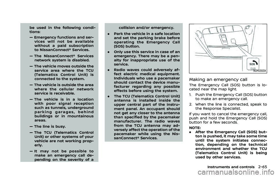
Making an emergency call
The Emergency Call (SOS) button is lo-
cated near the map light.
1. Push the Emergency Call (SOS) button
to make an emergency call.
2. When the line is connected, speak to the Response Specialist.
If you want to cancel the emergency call,
push and hold the Emergency Call (SOS)
button for a few seconds.
NOTE:
. After the Emergency Call (SOS) but-
ton is pushed, it may take some time
until the system initiates connec-
tion, depending on the technical
environment and whether the TCU
(Telematics Control Unit) is being
used by other services.
Instruments and controls2-65
Page 158 of 603
2-66Instruments and controls
.An indicator light on the Emergency
Call (SOS) button shows the readi-
ness of the emergency support sys-
tem. If the indicator light is not
illuminated, pushing the Emergency
Call (SOS) button does not connect
your vehicle to the Response Spe-
cialist.
The indicator light blinks while con-
nected to the NissanConnect® Ser-
vices Response Center.
. Even when the indicator light is
illuminated, connection to the Nis-
sanConnect® Services Response
Center may not be possible. If this
occurs in an emergency situation,
contact the authorities by other
means.
. To avoid disconnecting the line,
keep the engine running during an
emergency call, if it is safe to do so.CUP HOLDERS
CAUTION
.Avoid abrupt starting and braking
when the cup holder is being
used to prevent spilling the drink.
If the liquid is hot, it can scald you
or your passenger.
. Use only soft cups in the cup
holder. Hard objects can injure
you in an accident.
. Do not recline the rear seatback
when you use the cup holders on
the rear armrest. Doing so may
cause the beverages to spill over,
and if they are hot, they may
scald the passengers.
WAC0622X
Front
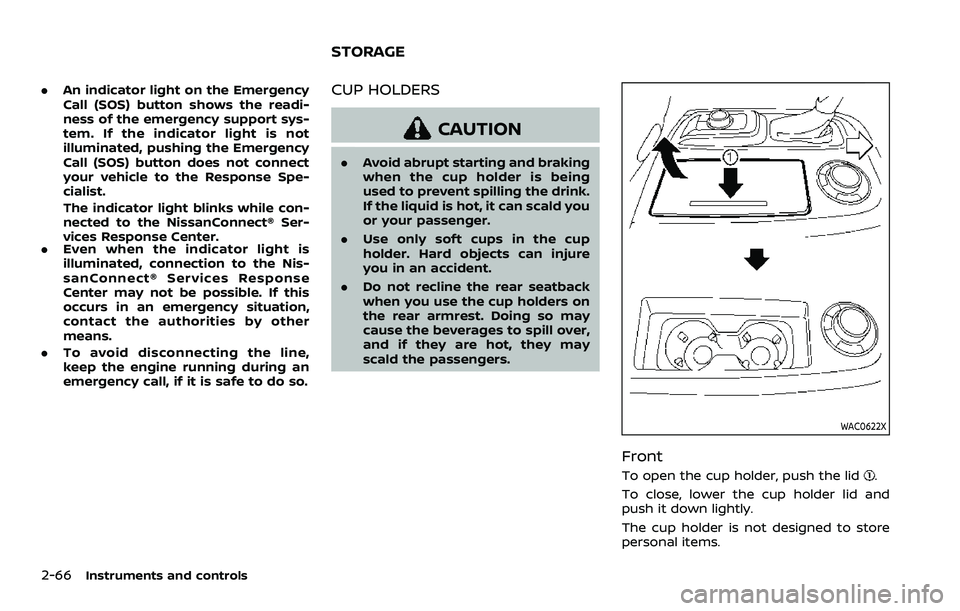
To open the cup holder, push the lid.
To close, lower the cup holder lid and
push it down lightly.
The cup holder is not designed to store
personal items.
STORAGE
Page 164 of 603
2-72Instruments and controls
WAC0626X
ROOF RACK
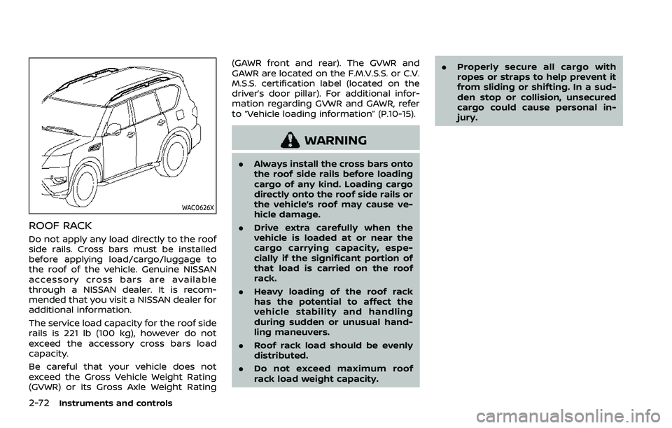
Do not apply any load directly to the roof
side rails. Cross bars must be installed
before applying load/cargo/luggage to
the roof of the vehicle. Genuine NISSAN
accessory cross bars are available
through a NISSAN dealer. It is recom-
mended that you visit a NISSAN dealer for
additional information.
The service load capacity for the roof side
rails is 221 lb (100 kg), however do not
exceed the accessory cross bars load
capacity.
Be careful that your vehicle does not
exceed the Gross Vehicle Weight Rating
(GVWR) or its Gross Axle Weight Rating(GAWR front and rear). The GVWR and
GAWR are located on the F.M.V.S.S. or C.V.
M.S.S. certification label (located on the
driver’s door pillar). For additional infor-
mation regarding GVWR and GAWR, refer
to “Vehicle loading information” (P.10-15).
WARNING
.
Always install the cross bars onto
the roof side rails before loading
cargo of any kind. Loading cargo
directly onto the roof side rails or
the vehicle’s roof may cause ve-
hicle damage.
. Drive extra carefully when the
vehicle is loaded at or near the
cargo carrying capacity, espe-
cially if the significant portion of
that load is carried on the roof
rack.
. Heavy loading of the roof rack
has the potential to affect the
vehicle stability and handling
during sudden or unusual hand-
ling maneuvers.
. Roof rack load should be evenly
distributed.
. Do not exceed maximum roof
rack load weight capacity. .
Properly secure all cargo with
ropes or straps to help prevent it
from sliding or shifting. In a sud-
den stop or collision, unsecured
cargo could cause personal in-
jury.
Page 165 of 603
POWER WINDOWS
WARNING
The driver is always responsible for
all the power window operation in-
cluding passenger’s operation. Be
sure to observe the following warn-
ings for safety.
.Never allow anyone to extend any
portion of their body or objects
out of the opening while the
vehicle is in motion. Otherwise
they may be seriously damaged
by coming into contact with ob-
jects outside the vehicle or when
abruptly braking.
. Make sure that all passengers
have their hands, etc. inside the
vehicle before operating the
power windows. Do not intention-
ally activate the auto-reverse
function. If their hands or faces
are caught in the windows, it
could cause serious injury.
. Never allow children to operate
the power window. Improper op-
eration by children could lead to
an accident. Depress the window
lock button since children or
other persons could be caught in the power window and this may
cause serious damage.
. When operating the power win-
dows, let children know it and
make sure that their hands, arms,
etc. are not placed near the
power windows. Otherwise they
may be caught in the power
windows.
. Make sure that the ignition switch
is in the OFF position and do not
leave the Intelligent Key and chil-
dren unattended inside the vehi-
cle. They could unknowingly
activate switches or controls. Un-
attended children could become
involved in serious accidents.
. To help avoid risk of injury or
death through unintended opera-
tion of the vehicle and or its
systems, including entrapment
in windows or inadvertent door
lock activation, do not leave chil-
dren, people who require the
assistance of others or pets un-
attended in your vehicle. Addi-
tionally, the temperature inside a
closed vehicle on a warm day can
quickly become high enough to
cause a significant risk of injury
or death to people and pets. The power windows operate when the
ignition switch is in the ON position, or for
a period of time after the ignition switch is
placed in the OFF position. If the driver’s
or front passenger’s door is opened dur-
ing this period of time, power to the
windows is canceled.
Instruments and controls2-73
WINDOWS
Page 166 of 603
2-74Instruments and controls
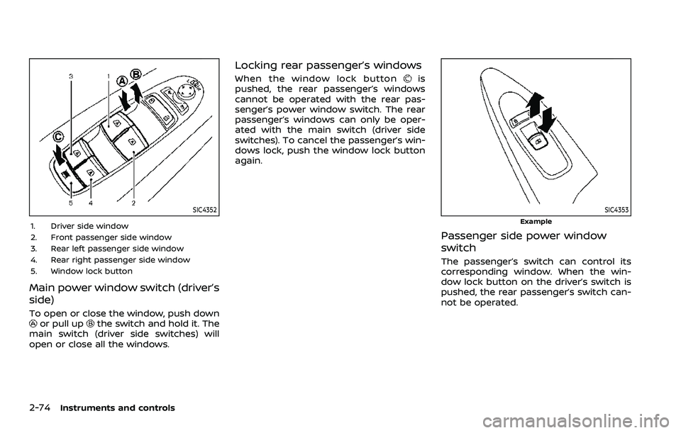
SIC4352
1. Driver side window
2. Front passenger side window
3. Rear left passenger side window
4. Rear right passenger side window
5. Window lock button
Main power window switch (driver’s
side)
To open or close the window, push downor pull upthe switch and hold it. The
main switch (driver side switches) will
open or close all the windows.
Locking rear passenger’s windows
When the window lock buttonis
pushed, the rear passenger’s windows
cannot be operated with the rear pas-
senger’s power window switch. The rear
passenger’s windows can only be oper-
ated with the main switch (driver side
switches). To cancel the passenger’s win-
dows lock, push the window lock button
again.
SIC4353
Example
Passenger side power window
switch
The passenger’s switch can control its
corresponding window. When the win-
dow lock button on the driver’s switch is
pushed, the rear passenger’s switch can-
not be operated.
Page 174 of 603
2-82Instruments and controls
JVI0428X
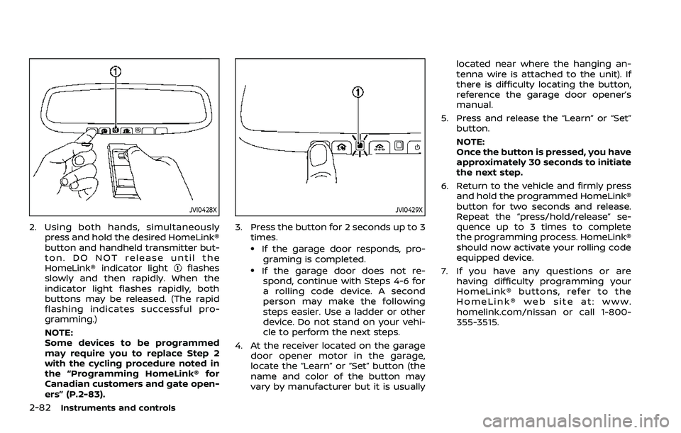
2. Using both hands, simultaneouslypress and hold the desired HomeLink®
button and handheld transmitter but-
ton. DO NOT release until the
HomeLink® indicator light
flashes
slowly and then rapidly. When the
indicator light flashes rapidly, both
buttons may be released. (The rapid
flashing indicates successful pro-
gramming.)
NOTE:
Some devices to be programmed
may require you to replace Step 2
with the cycling procedure noted in
the “Programming HomeLink® for
Canadian customers and gate open-
ers” (P.2-83).
JVI0429X
3. Press the button for 2 seconds up to 3 times.
.If the garage door responds, pro-graming is completed.
.If the garage door does not re-spond, continue with Steps 4-6 for
a rolling code device. A second
person may make the following
steps easier. Use a ladder or other
device. Do not stand on your vehi-
cle to perform the next steps.
4. At the receiver located on the garage door opener motor in the garage,
locate the “Learn” or “Set” button (the
name and color of the button may
vary by manufacturer but it is usually located near where the hanging an-
tenna wire is attached to the unit). If
there is difficulty locating the button,
reference the garage door opener’s
manual.
5. Press and release the “Learn” or “Set” button.
NOTE:
Once the button is pressed, you have
approximately 30 seconds to initiate
the next step.
6. Return to the vehicle and firmly press and hold the programmed HomeLink®
button for two seconds and release.
Repeat the “press/hold/release” se-
quence up to 3 times to complete
the programming process. HomeLink®
should now activate your rolling code
equipped device.
7. If you have any questions or are having difficulty programming your
HomeLink® buttons, refer to the
HomeLink® web site at: www.
homelink.com/nissan or call 1-800-
355-3515.
Page 176 of 603
2-84Instruments and controls
CLEARING THE PROGRAMMED IN-
FORMATION
The following procedure clears the pro-
grammed information from both buttons.
Individual buttons cannot be cleared.
However, individual buttons can be re-
programmed, see “Reprogramming a sin-
gle HomeLink® button” (P.2-84).
To clear all programming
1. Press and hold the two outerHomeLink® buttons until the indicator
light begins to flash in approximately
10 seconds. Do not hold for longer
than 20 seconds.
2. Release both buttons.
HomeLink® is now in the programming
mode and can be programmed at any
time beginning with “Programming
HomeLink®” - Step 1.
REPROGRAMMING A SINGLE
HomeLink® BUTTON
To reprogram a HomeLink® Universal
Transceiver button, complete the follow-
ing.
1. Press and hold the desired HomeLink® button. Do notrelease the button.
2. The indicator light will begin to flash after 20 seconds. Without releasing
the HomeLink® button, proceed with “Programming HomeLink®” - Step 1.
For questions or comments, contact
HomeLink® at: www.homelink.com/
nissan or 1-800-355-3515.
The HomeLink® Universal Transceiver
button has now been reprogrammed.
The new device can be activated by
pushing the HomeLink® button that was
just programmed. This procedure will not
affect any other programmed HomeLink®
buttons.
IF YOUR VEHICLE IS STOLEN
If your vehicle is stolen, you should
change the codes of any non-rolling code
device that has been programmed into
HomeLink®. Consult the Owner’s Manual
of each device or call the manufacturer or
dealer of those devices for additional
information.
When your vehicle is recovered, you will
need to reprogram the HomeLink® Uni-
versal Transceiver with your new trans-
mitter information.
FCC Notice:
For USA:
This device complies with Part 15 of the
FCC Rules. Operation is subject to the
following two conditions: (1) This device
may not cause harmful interference,
and (2) this device must accept any interference received, including inter-
ference that may cause undesired op-
eration.
NOTE:
Changes or modifications not expressly
approved by the party responsible for
compliance could void the user’s
authority to operate the equipment.
For Canada:
This device complies with Industry Ca-
nada licence-exempt RSS standard(s).
Operation is subject to the following
two conditions: (1) this device may not
cause interference, and (2) this device
must accept any interference, including
interference that may cause undesired
operation of the device.