2021 MERCEDES-BENZ GLE COUPE battery
[x] Cancel search: batteryPage 201 of 525
If
th efo llowing conditions are fulfilled, standby
mode can be activated or deactivated using the
multimedia sy stem:
R The engine is switched off.
R The ignition is switched on.
Exceeding theve hicle's displa yed non-opera‐
tional time may cause incon venience, i.e. it can‐
not be guaranteed that thest ar ter battery will
re liably start the engine.
The star ter battery must be charge dfirs t in the
fo llowing situations:
R The vehicle's non-operational time must be
ex tended.
R The Battery charge insufficient for standby
mode messa geappears in the media displa y.
% Standby mode is automatically deactivated
when the ignition is switched on.
Ac tivating/deactivating standby mode (park‐
ing up theve hicle)
Re quirements:
R The engine is switched off. Multimedia sy
stem:
4 © 5
Settings 5
Vehicle #
Activate or deacti vate Standby mode. #
Select Yes. Driving and driving saf
ety sy stems Driving sy
stems and your responsibility Yo
ur vehicle is equipped with driving sy stems
which assist you in driving, parking and manoeu‐
vring theve hicle. The driving sy stems are only
aids. They are not a substitute foryo ur attention
to the sur roundings and do not relie ve you of
yo ur responsibility per taining toroad traf fic la w.
The driver is alw aysre sponsible for maintaining
a safe dis tance totheve hicle in front, forve hicle
speed, for braking in good time and forst ay ing
in lane. Pay attention tothe tra ffic conditions at
all times and inter vene when necessary . Be
aw are of the limitations rega rding the safe use of
th ese sy stems.
Driving sy stems can neither reduce therisk of
accident if youfa ilto adapt your driving style nor
ove rride the la wsof ph ysics. They cannot alw aysta
ke into account road, weather or traf fic condi‐
tions. In
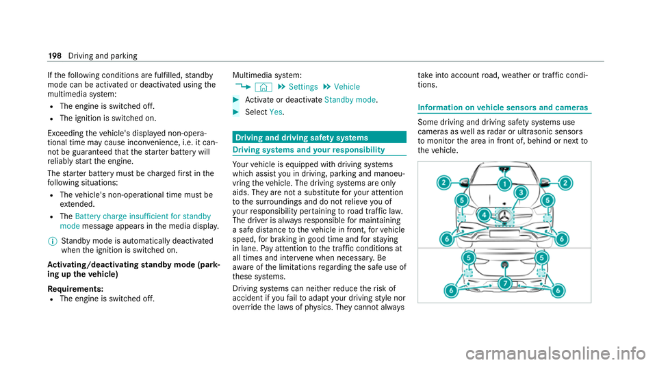
fo rm ation on vehicle sensors and cameras Some driving and driving saf
ety sy stems use
cameras as well as radar or ultrasonic sensors
to monitor the area in front of, behind or next to
th eve hicle. 19 8
Driving and pa rking
Page 244 of 525
%
Further information on AIRMATIC
(/ page 237).
Lo weri ng and raising there ar of theve hicle &
WARNING Risk of entrapment from vehi‐
cle lo wering
When lo wering theve hicle, other people
could become trapped if their limbs are
between theve hicle body and the tyres or
underneath theve hicle. #
Make sure no one is underneath the
ve hicle or in the immediate vicinity of
th e wheel ar ches when theve hicle is
being lo wered. Re
quirements:
R allvehicle doors are closed
R there is no trailer coupled
R there is no bicycle rack fitted
R the battery is suf ficiently charge d (if neces‐
sar y,start the engine) Lo
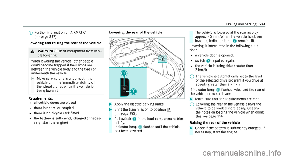
weri ngthere ar of theve hicle #
Apply the electric parking brake. #
Shift the transmission toposition 005D
(/ page 182). #
Pull swit ch1 inthe load compartment trim
brief ly.
Indicator lamp 2flashes until theve hicle
has been lo wered. The
vehicle is lo wered at there ar axle by
appr ox. 40 mm. When theve hicle has been
lo we red, indicator lamp 2remains lit.
Lo we ring is inter rupte d in thefo llowing situa‐
tions:
R ave hicle door is opened.
R switch 1is pulled again.
R theve hicle is being driven fasterthan
2 km/h.
% The vehicle is automatically set tothe le vel
of the selected drive prog ram if you drive at
speeds greater than 2 km/h.
If indicator lamp 2flashes twice and there ar of
th eve hicle does not lo wer: #
Make sure that there qu irements are met.
% Lowe ring there ar of theve hicle allo wsthe
ve hicle tobe loaded more easil y.Obser ve
th e no tes on loading theve hicle when doing
th is (/ page114).
Ra ising there ar of theve hicle #
Che ckifth e battery is suf ficiently charge d. If
necessar y,start the engine. Driving and parking
241
Page 245 of 525
#
Pull switch 1briefly.
Indicator lamp 2goes out.
The vehicle will be raised tothe cur rently
selected le vel.
% The vehicle is automatically set tothe le vel
of the selected drive prog ram if you drive at
speeds greater than 2 km/h.
If th eve hicle cannot be raised: #
Ensure that the battery is suf ficiently
ch arge d; if necessar y,start the engine.
The raising process continues. E-
AC TIVE BODY CONT ROL Fu
nction of E- ACTIVE BODY CONT ROL
E- AC TIVE BODY CONTROL is an electrohydraulic
suspension sy stem with variable damping for
impr oved driving comfort. The all-round le vel
control sy stem ensures the best possible sus‐
pension and const ant ground clearance, even
with a laden vehicle. When driving at speed, the
ve hicle is lo wered automatically toimpr ovedriv‐
ing saf ety and toreduce fuel consum ption. The
suspension setting is adjus ted depending on thero
ad sur face, vehicle load and the drive program
selected.
The ROAD SUR FACE SCAN function de tects
areas of une venness in thero ad before you drive
ove rth em bymeans of a multifunction camera.
This reduces chassis mo vements.
The damping is adju sted individually toeach
wheel and depends on thefo llowing factors:
R Driving style, e.g. sporty
R Road condition, e.g. bumps
R Drive program
E- AC TIVE BODY CONTROL is comprised of the
fo llowing functions and components:
R Vehicles with Driving Assistance Pack‐
age: ROAD SUR FACE SCAN
R Cur veinclination function CURVE
R Recovery mode
R Individual wheel control
R Air suspension with auto matic level control
R Speed-dependent lo wering toreduce fuel
consum ption R
Manual le vel adjustment
R ADS PLUS: Adaptive Damping Sy stem with
const ant adjustment of damping characteris‐
tics
R DYNA MIC SELECT switch and le vel button
Suspension setting and vehicle le vel per
drive prog ram
Drive prog ram C
R The suspension setting is firm er.
R The vehicle is set toSport le vel.
R ROAD SUR FACE SCAN is deactivated.
R The cur veinclination function is deactivated.
Drive program B
R The suspension setting is even firm er.
R The vehicle is set toSport + le vel.
R ROAD SUR FACE SCAN is deactivated.
R The cur veinclination function is active.
Drive prog ram A
R The suspension setting is comfor table.
R The vehicle is set tothe normal le vel. 242
Driving and pa rking
Page 274 of 525
R
Blind Spot Assi stor Active Blind Spot Assi st
R Drive AwayAssi st
R Cross Traf fic Alert
R Reversing camera
R 360° Camera
R AIRMATIC
R E-AC TIVE BODY CONTROL
Coupling up a trailer
* NO
TEDama getothest ar ter battery due
to full discharge Charging
the trailer battery using the po wer
supply of the trailer can damage thest ar ter
batter y. #
Do not use theve hicle's po wer supply
to charge the trailer batter y. #
Remo vethe co ver cap from the ball head and
st ore it in a safe place. #
Position the trailer on a le vel sur face behind
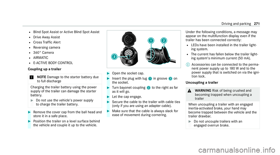
th eve hicle and couple it up totheve hicle. #
Open the soc ket cap. #
Inse rtthe plug with lug 1in groo ve3 on
th e soc ket. #
Turn bayonet coupling 2totheright as far
as it will go. #
Let the cap engage. #
Secure the cable tothe trailer with cable ties
(only if you are using an adap ter cable). #
Make sure that the cable is alw ays slack for
ease of mo vement during cornering. Under
thefo llowing conditions, a message may
appear on the multifunction display even if the
trailer has been connected cor rectly:
R LEDs ha vebeen ins talled in the trailer light‐
ing sy stem.
R The cur rent has fallen below the trailer light‐
ing sy stem's minimum cur rent (50 mA).
% Accessories can be connected tothe perma‐
nent po wer supp lyup to180 W and tothe
po we r supp lythat is swit ched on via the igni‐
tion loc k.
Un coupling a trailer &
WARNING Risk of being crushed and
becoming trapped when uncoupling a
trailer
When uncoupling a trailer with an engaged
ine rtia-activated brake, your hand may
become trapped between theve hicle and the
trailer dr awbar. #
Do not uncouple trailers with an
engaged overrun brake. Driving and pa
rking 271
Page 287 of 525
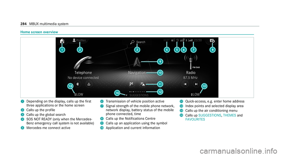
Home screen
overview 1
Depending on the displa y,calls up thefirst
th re e applications or the home screen
2 Calls up the profile
3 Calls up theglobal sear ch
4 SOS NOT READY (only when the Mercedes-
Benz emer gency call sy stem is not available)
5 Mercedes me connect active 6
Transmission of vehicle position active
7 Signal stre ngth of the mobile phone networ k,
network displ ay, battery status of the mobile
phone connected, time
8 Calls up the Notifications Centre
9 Calls up an application using the symbol
A Application and cur rent information B
Quick-access, e.g. enter home address
C Index points and selected displ ayarea
D Calls up the air conditioning menu
E Calls up SUGGESTIONS, THEMESand
FAVOURITES 284
MBUX multimedia sy stem
Page 310 of 525
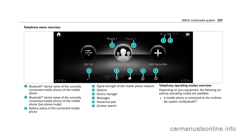
Te
lephone menu overview 1
Blue tooth ®
device name of the cur rently
connected mobile phone/of the mobile
phone
2 Blue tooth ®
device name of the cur rently
connected mobile phone/of the mobile
phone (two phone mode)
3 Battery status of the connected mobile
phone 4
Signal stre ngth of the mobile phone network
5 Options
6 Device manager
7 Messages
8 Nume rical pad
9 Contact search Te
lephony operating modes overview
Depending on your equipment, thefo llowing tel‐
ephony operating modes are available:
R A mobile phone is connec tedto the multime‐
dia sy stem via Blue tooth®
. MBUX multimedia sy
stem 307
Page 323 of 525
%
Ifth ere is a malfunction in the emer gency
call sy stem (e.g. a fault with the speaker,
microphone, airbag, SOS button), a cor re‐
sponding message appears inthe multifunc‐
tion display of the instrument clus ter. Tr
iggering an automatic emer gency call Re
quirements:
R The ignition is switched on.
R The star ter battery is suf ficiently charge d.
Bo th th e Mercedes-Benz emer gency call sy stem
as well as the11 2 emergency call sy stem (EU
eCall) automatically initiate an emer gency call
af te r:
R Activation of there stra int sy stems such as
airbags or seat belt tensioners af ter an acci‐
dent
The emergency call has been made:
R Avo ice connection is es tablished with the
emer gency call centre.
R A messa gewith accident data is transmitted
to the emer gency call centre. The SOS button in
theove rhead control panel
fl ashes until the emer gency call is finished.
If no connection can be made tothe public
emer gency services, a cor responding message
appears inthe displa y. #
Dial the emer gency number 112 or an app ro‐
priate local emer gency call number on your
mobile phone.
If an eme rgency call has been initiated:
R Remain in theve hicle if thero ad and traf fic
conditions permit youto do so until a voice
connection is es tablished with the emer‐
ge ncy call centre.
R Onthe basis of the call, the emer gency call
centre decides wh ether it is necessary tocall
re scue teams and/or the police tothe acci‐
dent site.
R If no vehicle occupant answers, an ambu‐
lance is sent totheve hicle immediatel y. Tr
iggering a manual emer gency call #
Touse the SOS but ton in theov erhead
control panel: pressthe SOS button at least
one second long (/ page310). #
Touse voice control: usethe LINGUA‐
TRONIC voice commands .
The emer gency call has been made:
R Avo ice connection is es tablished with an
emer gency call centre.
R Remain in theve hicle if thero ad and traf fic
conditions permit youto do so until a voice
connection is es tablished with the emer‐
ge ncy call centre.
R Onthe basis of the call, the emer gency call
centre decides wh ether it is necessary tocall
re scue teams and the police tothe accident
site.
R A message with accident data is transmit ted
to the emer gency call centre.
If no connection can be made tothe public
emer gency services, a cor responding message
appears inthe media displa y.320
MBUX multimedia sy stem
Page 326 of 525
Fo
r accident clarification purposes, thefo llowing
measures can be take n up toan hour af terthe
emer gency call has been initia ted:
R The cur rent vehicle position can be de ter‐
mined.
R Avo ice connection totheve hicle occupants
can be es tablished.
R Emer gency call da tacan be called up.
% ForRu ssia: various functions, e.g. receiving
traf fic information, cannot be per form ed for
up totwo hou rsafte r sending an emer gency
call. Self diagnosis function of the eme
rgency call
sy stem Yo
ur car verifies the operability of the emer‐
ge ncy call sy stem each time the ignition is ON.
In case of sy stem failure, you will be informed
with text messa geon the instrument clus ter and
with red indicator SOS NOT READY onthe dis‐
pla y.
Please, make sure, that during 30 seconds af ter
switching ignition ON there d indicator SOS NOT READY
inthe upper right corner of display
is switched OFF, this means the emer gency call
sy stem passed diagnostics successfully. St
arting/ending ERA-GLONASS test mode Re
quirements:
R The star ter battery is suf ficiently charge d.
R The ignition is switched on.
R The vehicle has been stationary for at least
one minute.
% The test mode is cur rently available in the
fo llowing countries, forex ample:
R Russia
R Belarus
R Kazakh stan
R Armenia
R Kyrgyzs tan #
Tostart thete st mode: press and hold the
0076 button on the multifunction steering
wheel for at least five seconds.
The test mode is star ted and automatically
ends af terth e language test has been per‐
fo rm ed. #
Toend thete st mode manuall y:switch off
th e ignition.
The test mode is ended. Information on data processing
Processing of personal data via
the
Mercedes-Benz emer gency call sy stem
All processing of personal data via the
Mercedes-Benz emer gency call sy stem cor re‐
sponds with the specifications in the EU Regula‐
tion 20 16/679 "on the pr otection of individuals
with rega rd tothe processing of personal data
(GDPR)".
The data is solely used bythe Mercedes-Benz
emer gency call sy stem forre scue and reco very
in theeve nt of an accident. MBUX multimedia sy
stem 323