Page 595 of 630
Maintenance
9-48
Engine compartment fuse panel
Fuse Name Fuse ratingCircuit Protected
MDPS 80A/100A MDPS Unit (Column Type-80A) / MDPS Unit (Rack Type-
100A)
C/FAN 80ACooling Fan Motor
B+1 60AICU Junction Block (IPS01, IPS02, IPS03, IPS04, IPS05)
B+3 60AICU Junction Block (Power Window Main Relay, Fuse : F2,
F3, F5, F6, F8, F9, F11, F12, F18, F15)
CVVD 50ACVVD Actuator
Bower 40AE/R Junction Block (RLY.10)
IEB3 40AIEB Unit
Rear Defogger 40AE/R Junction Block (RLY.14)
Trailer1 50ATrailer Connector Unit
B+4 50AICU Junction Block (Long Term Load Latch Relay, Fuse : F1,
F4, F14, F17, F20, F21, F24, F27)
IEB2 60AIEB Unit
IEB1 60AIEB Unit
B+2 50AICU Junction Block (IPS06, IPS07, IPS08, IPS10, IPS11)
PTC Heater 50AE/R Junction Block (RLY.13)
PTG 40APower Tailgate Unit
E-Shifter1 30ASCU
Fuel Pump 20AE/R Junction Block (RLY.7)
AWD 20AAWD ECM
ECU4 10AECM
IG3 20AE/R Junction Block (RLY.3)
Page 596 of 630
09
9-49
Fuse Name Fuse ratingCircuit Protected
OPCU 20AOPU
BATT C/FAN 15A E/R Junction Block (RLY.2) E-Shifter2 10ASCU, Electronic Shift Switch (SBW)
HPCU1 10AHPCU
Trailer2 20ATrailer Connector Unit
RR HTD 10ADriver Power Outside Mirror, Passenger Power Outside
Mirror
IG1 30APCB Block (PDM(IG1) Relay)
IG2 30APCB Block (PDM(IG2) Relay)
ECU3 10ACVVD Actuator, ECM
TCU2 15A TCM, OPU
IEB4 10AIEB Unit
Module 7.5A Electronic Water Pump (Engine) AEB 10AFront Radar
HPCU2 10AHCPU
Sensor1 20AIgnition Coil #1~#4
Sensor2 15A Oxygen Sensor (Up/Down) ECU1 20AECM
Sensor4 10AE/R Junction Block (RLY.7)
Sensor3 10AOil Control Valve #1~#2, Purge Control Solenoid Valve,
RCV Control Solenoid Valve, Variable Oil Pump, Cooling
Fan Motor
B/Horn 15A PCB Block (Burglar Alarm Horn Relay)
Page 597 of 630
Maintenance
9-50
Fuse Name Fuse ratingCircuit Protected
MDPS2 10AMDPS Unit (Rack Type)
Sensor5 15A Active Purge Pump Horn 15A PCB Block (Horn Relay)
Wiper(FR)2 7.5A IBU Wiper(RR) 15A ICU Junction Block (Rear Wiper Relay)
Wiper(FR)1 25A PCB Block (Front Wiper(Low) Relay), Front Wiper Motor P/Outlet1 20ALuggage Power Outlet
P/Outlet2 20AFront Power Outlet
ACC 20AICU Junction Block (Fuse : F33, F36)
TCU1 15ATCM
EWP 10AElectronic Water Pump (Engine)
BMS 10ABMS
ECU2 15AECM
Page 598 of 630

09
9-51
We recommend that you consult an
authorized HYUNDAI dealer to replace
most vehicle light bulbs. It is difficult
to replace vehicle light bulbs because
other parts of the vehicle must be
removed before you can get to the bulb.
This is especially true for removing the
headlamp assembly to get to the bulb(s).
Removing/installing the headlamp
assembly can result in damage to the
vehicle.
WARNING
• Prior to working on a light, depress
the foot brake, shift to P (Park), apply
the parking brake, set the ignition
switch to the LOCK/OFF position
and take the key with you when
leaving the vehicle to avoid sudden
movement of the vehicle and to
prevent possible electric shock.
• Be aware the bulbs may be hot and
may burn your fingers.
NOTICE
Be sure to replace the burned-out bulb
with one of the same wattage rating.
Otherwise, it may cause damage to the
fuse or electrical wiring system.
NOTICE
To prevent damage, do not clean the
headlamp lens with chemical solvents
or strong detergents.
Information
The headlamp and tail lamp lenses could
appear frosty if the vehicle is washed after
driving or the vehicle is driven at night
in wet weather. This condition is caused
by temperature difference between the
lamp inside and outside and, it does not
indicate a problem with your vehicle.
When moisture condenses in the lamp,
it will be removed after driving with the
headlamp on. The removable level may
differ depending on lamp size, lamp
position and environmental condition.
However, if moisture is not removed, we
recommend that your vehicle is inspected
by an authorized HYUNDAI dealer.
Information
• A normally functioning lamp may
flicker momentarily to stabilize the
vehicle’s electrical control system.
However, if the lamp goes out after
flickering momentarily, or continues to
flicker, we recommend the system be
checked by an authorized HYUNDAI
dealer.
• The position lamp may not turn on
when the position lamp switch is turned
on, but the position lamp and headlamp
switch may turn on when the headlamp
switch is turned on. This may be caused
by network failure or vehicle electrical
control system malfunction. If this
occurs, we recommend the system be
checked by an authorized HYUNDAI
dealer.
Information
The headlamp aiming should be adjusted
after an accident or after the headlamp
assembly is reinstalled at an authorized
HYUNDAI dealer.
light bulbs
Page 600 of 630

09
9-53
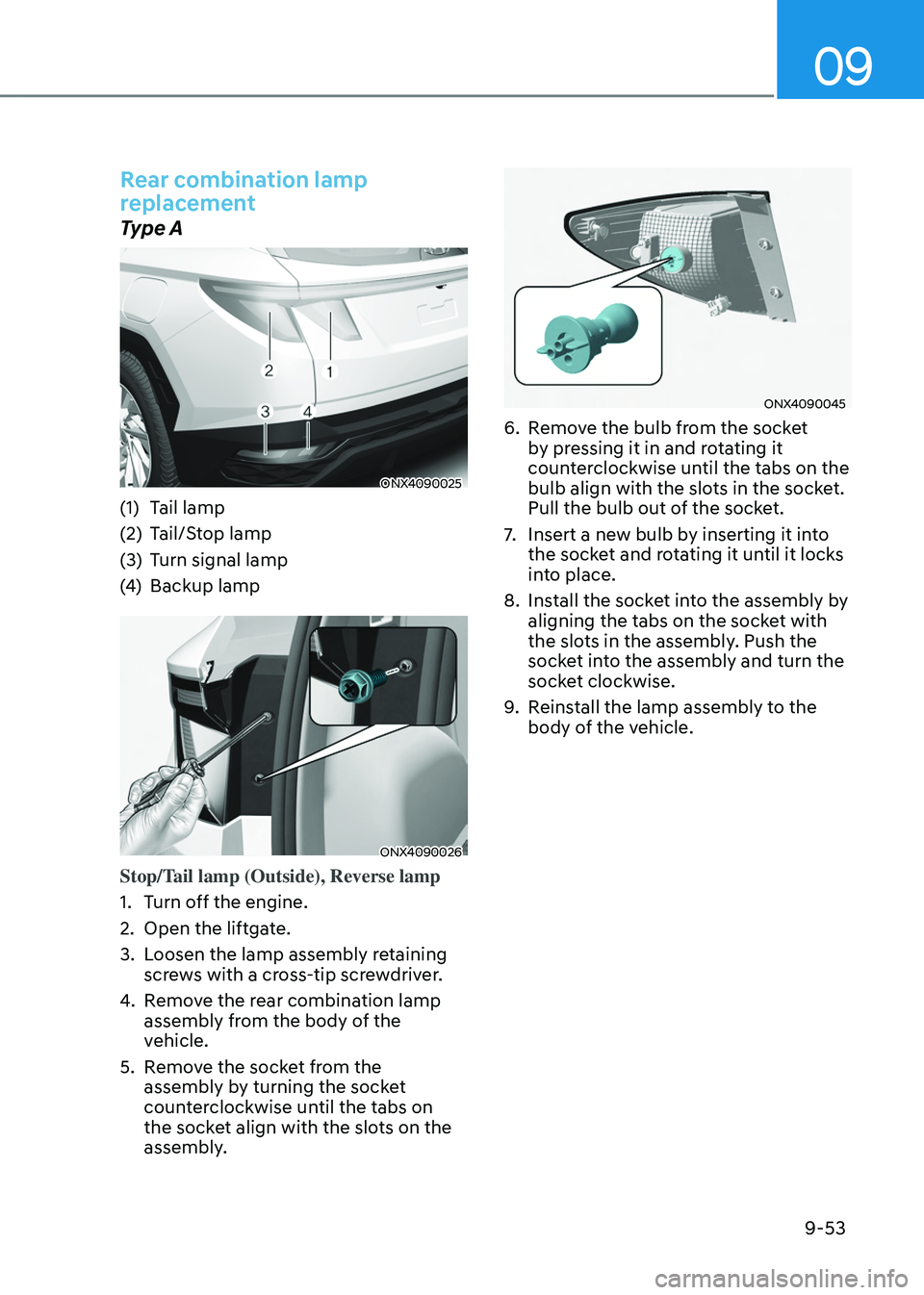
Rear combination lamp
replacement
Type A
ONX4090025
(1) Tail lamp
(2)
Tail/S
top lamp
(3)
Turn signal lamp
(4
)
Backup lamp
ONX4090026
Stop/Tail lamp (Outside), Reverse lamp
1.
Turn o
ff the engine.
2.
Open the liftga
te.
3.
Loosen the lamp assembly r
etaining
screws with a cross-tip screwdriver.
4.
Remo
ve the rear combination lamp
assembly from the body of the
vehicle.
5.
Remo
ve the socket from the
assembly by turning the socket
counterclockwise until the tabs on
the socket align with the slots on the
assembly.
ONX4090045
6. Remove the bulb from the socket
b y pressing it in and rotating it
counterclockwise until the tabs on the
bulb align with the slots in the socket.
Pull the bulb out of the socket.
7.
Insert a new bulb b
y inserting it into
the socket and rotating it until it locks
into place.
8.
Install the sock
et into the assembly by
aligning the tabs on the socket with
the slots in the assembly. Push the
socket into the assembly and turn the
socket clockwise.
9.
Reins
tall the lamp assembly to the
body of the vehicle.
Page 601 of 630
Maintenance
9-54
ONX4090027
Tail lamp (Inside)
1.
Turn o
ff the engine.
2.
Open the liftga
te.
3.
Remo
ve the service cover using a
flat-blade screwdriver.
4.
Remo
ve the socket from the
assembly by turning the socket
counterclockwise until the tabs on
the socket align with the slots on the
assembly.
ONX4090028
5. Remove the bulb from the socket
b y pressing it in and rotating it
counterclockwise until the tabs on the
bulb align with the slots in the socket.
Pull the bulb out of the socket.
6.
Insert a new bulb b
y inserting it into
the socket and rotating it until it locks
into place.
7.
Install the sock
et into the assembly by
aligning the tabs on the socket with
the slots in the assembly. Push the
socket into the assembly and turn the
socket clockwise.
8.
Reins
tall the lamp assembly to the
body of the vehicle.
Page 602 of 630
09
9-55
ONX4090029
Turn signal lamp
ONX4090030
Back-up lampTurn signal lamp, Back-up lamp
1.
Disconnect the negativ
e battery
cable.
2.
Loosen the r
etaining clips under the
bumper and screws on the wheel
house trim.
3.
Pre
y trim under the bumper toward
the vehicle.
4.
Remo
ve the socket from the
assembly by turning the socket
counterclockwise until the tabs on
the socket align with the slots on the
assembly.
5.
Remo
ve the bulb by pulling it straight
out.
6.
Insert a new bulb in the sock
et.
7.
Reins
tall the light assembly to the
body of the vehicle.
Page 606 of 630

09
9-59
appEarancE carE
Exterior care
Exterior general caution
It is very important to follow the label
directions when using any chemical
cleaner or polish. Read all warning and
caution statements that appear on the
label.
Finish maintenance
Washing
To help protect your vehicle’s finish from
rust and deterioration, wash it thoroughly
and frequently at least once a month
with lukewarm or cold water.
If you use your vehicle for off-road
driving, you should wash it after each
off-road trip. Pay special attention to the
removal of any accumulation of salt, dirt,
mud, and other foreign materials. Make
sure the drain holes in the lower edges
of the doors and rocker panels are kept
clear and clean.
Insects, tar, tree sap, bird droppings,
industrial pollution and similar deposits
can damage your vehicle’s finish if not
removed immediately.
Even prompt washing with plain water
may not completely remove all these
deposits. A mild soap, safe for use on
painted surfaces, should be used.
After washing, rinse the vehicle
thoroughly with lukewarm or cold water.
Do not allow soap to dry on the finish.
High-pressure washing
• When using high-pressure washers,
make sure to maintain sufficient
distance from the vehicle.
Insufficient clearance or excessive
pressure can lead to component
damage or water penetration.
• Do not spray the camera, sensors or
its surrounding area directly with a
high pressure washer. Shock applied
from high pressure water may cause
the device to not operate normally.
• Do not bring the nozzle tip close to
boots (rubber or plastic covers) or
connectors as they may be damaged
if they come into contact with high
pressure water.
WARNING
After washing the vehicle, test the
brakes while driving slowly to see
if they have been affected by water
before getting on the road. If braking
performance is impaired, dry the
brakes by applying them lightly while
maintaining a slow forward speed.
NOTICE
• Do not use strong soap, chemical
detergents or hot water, and do not
wash the vehicle in direct sunlight
or when the body of the vehicle is
warm.
• Be careful when washing the side
windows of your vehicle.
• Especially, with high-pressure water,
water may leak through the windows
and wet the interior.
• To prevent damage to the plastic
parts, do not clean with chemical
solvents or strong detergents.
• To prevent damage to the charging
door, make sure to close and lock the
vehicle doors when washing (high-
pressure washing, automatic car
washing, etc.) the vehicle.