2021 HYUNDAI ELANTRA HYBRID fuel
[x] Cancel search: fuelPage 507 of 555
Maintenance
9-38
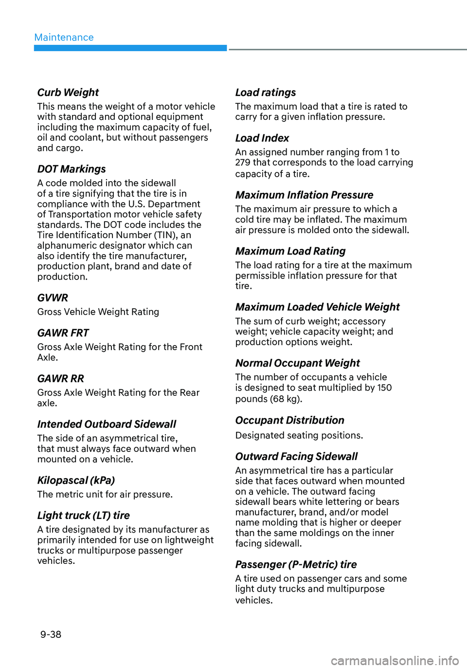
Curb Weight
This means the weight of a motor vehicle
with standard and optional equipment
including the maximum capacity of fuel,
oil and coolant, but without passengers
and cargo.
DOT Markings
A code molded into the sidewall
of a tire signifying that the tire is in
compliance with the U.S. Department
of Transportation motor vehicle safety
standards. The DOT code includes the
Tire Identification Number (TIN), an
alphanumeric designator which can
also identify the tire manufacturer,
production plant, brand and date of
production.
GVWR
Gross Vehicle Weight Rating
GAWR FRT
Gross Axle Weight Rating for the Front
Axle.
GAWR RR
Gross Axle Weight Rating for the Rear
axle.
Intended Outboard Sidewall
The side of an asymmetrical tire,
that must always face outward when
mounted on a vehicle.
Kilopascal (kPa)
The metric unit for air pressure.
Light truck (LT) tire
A tire designated by its manufacturer as
primarily intended for use on lightweight
trucks or multipurpose passenger
vehicles.
Load ratings
The maximum load that a tire is rated to
carry for a given inflation pressure.
Load Index
An assigned number ranging from 1 to
279 that corresponds to the load carrying
capacity of a tire.
Maximum Inflation Pressure
The maximum air pressure to which a
cold tire may be inflated. The maximum
air pressure is molded onto the sidewall.
Maximum Load Rating
The load rating for a tire at the maximum
permissible inflation pressure for that
tire.
Maximum Loaded Vehicle Weight
The sum of curb weight; accessory
weight; vehicle capacity weight; and
production options weight.
Normal Occupant Weight
The number of occupants a vehicle
is designed to seat multiplied by 150
pounds (68 kg).
Occupant Distribution
Designated seating positions.
Outward Facing Sidewall
An asymmetrical tire has a particular
side that faces outward when mounted
on a vehicle. The outward facing
sidewall bears white lettering or bears
manufacturer, brand, and/or model
name molding that is higher or deeper
than the same moldings on the inner
facing sidewall.
Passenger (P-Metric) tire
A tire used on passenger cars and some
light duty trucks and multipurpose
vehicles.
Page 519 of 555
Maintenance
9-50
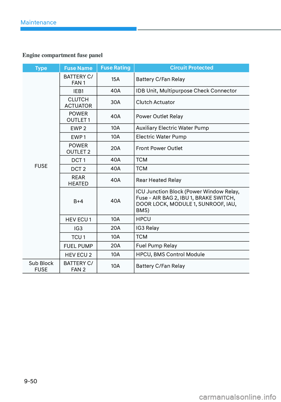
Engine compartment fuse panel
TypeFuse Name Fuse Rating
Circuit Protected
FUSE BATTERY C/
FAN 1 15A
Battery C/Fan Relay
IEB1 40A
IDB Unit, Multipurpose Check Connector
CLUTCH
ACTUATOR 30A
Clutch Actuator
POWER
OUTLET 1 40A
Power Outlet Relay
EWP 2 10A
Auxiliary Electric Water Pump
EWP 1 10A
Electric Water Pump
POWER
OUTLET 2 20A
Front Power Outlet
DCT 1 40A
TCM
DCT 2 40A
TCM
REAR
HEATED 40A
Rear Heated Relay
B+4 40AICU Junction Block (Power Window Relay,
Fuse - AIR BAG 2, IBU 1, BRAKE SWITCH,
DOOR LOCK, MODULE 1, SUNROOF, IAU,
BMS)
HEV ECU 1 10A
HPCU
IG3 20A
IG3 Relay
TCU 1 10A
TCM
FUEL PUMP 20A
Fuel Pump Relay
HEV ECU 2 10A
HPCU, BMS Control Module
Sub Block FUSE BATTERY C/
FAN 2 10A
Battery C/Fan Relay
Page 520 of 555

09
9-51
Engine compartment fuse panel
Fuse NameFuse Rating
Circuit Protected
WIPER 25A
Wiper Relay
HORN 15A
Horn Relay
IGN COIL 20A
Ignition Coil #1 ~ #4
ECU2 15A
ECM
SENSOR3 10A
E/R Junction Block (Fuel Pump Relay)
SENSOR2 10ACamshaft Position Sensor #1/#2 (Intake/Exhaust), Mass
Air Flow Sensor, ELCM, Oil Control Valve #1/#2 (Intake/
Exhaust),
Purge Control Solenoid Valve
ECU3 10A
ECM, HPCU, Clutch Actuator
SENSOR1 15A
Oxygen Sensor (Up/Down)
IEB 4 10A
IDB Unit, Multipurpose Check Connector
EWP 3 10A
Auxiliary Electric Water Pump
ECU1 20A
ECM
TCU2 15A
Transaxle Range Switch, TCM
Page 533 of 555
Maintenance
9-64
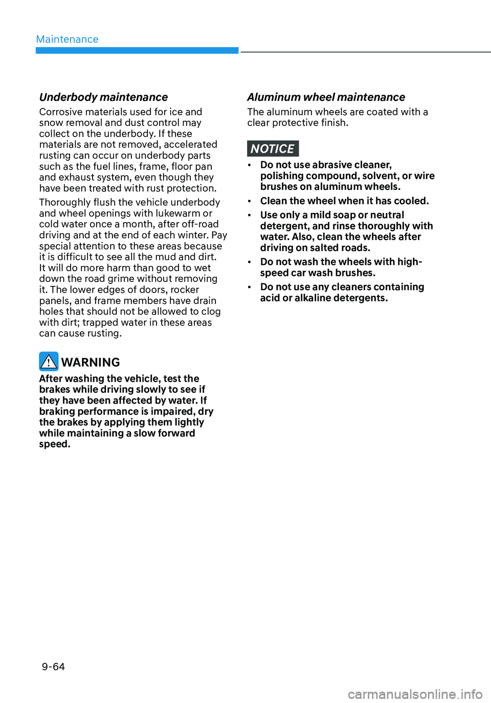
Underbody maintenance
Corrosive materials used for ice and
snow removal and dust control may
collect on the underbody. If these
materials are not removed, accelerated
rusting can occur on underbody parts
such as the fuel lines, frame, floor pan
and exhaust system, even though they
have been treated with rust protection.
Thoroughly flush the vehicle underbody
and wheel openings with lukewarm or
cold water once a month, after off-road
driving and at the end of each winter. Pay
special attention to these areas because
it is difficult to see all the mud and dirt.
It will do more harm than good to wet
down the road grime without removing
it. The lower edges of doors, rocker
panels, and frame members have drain
holes that should not be allowed to clog
with dirt; trapped water in these areas
can cause rusting.
WARNING
After washing the vehicle, test the
brakes while driving slowly to see if
they have been affected by water. If
braking performance is impaired, dry
the brakes by applying them lightly
while maintaining a slow forward
speed.
Aluminum wheel maintenance
The aluminum wheels are coated with a
clear protective finish.
NOTICE
• Do not use abrasive cleaner,
polishing compound, solvent, or wire
brushes on aluminum wheels.
• Clean the wheel when it has cooled.
• Use only a mild soap or neutral
detergent, and rinse thoroughly with
water. Also, clean the wheels after
driving on salted roads.
• Do not wash the wheels with high-
speed car wash brushes.
• Do not use any cleaners containing
acid or alkaline detergents.
Page 539 of 555
Maintenance
9-70
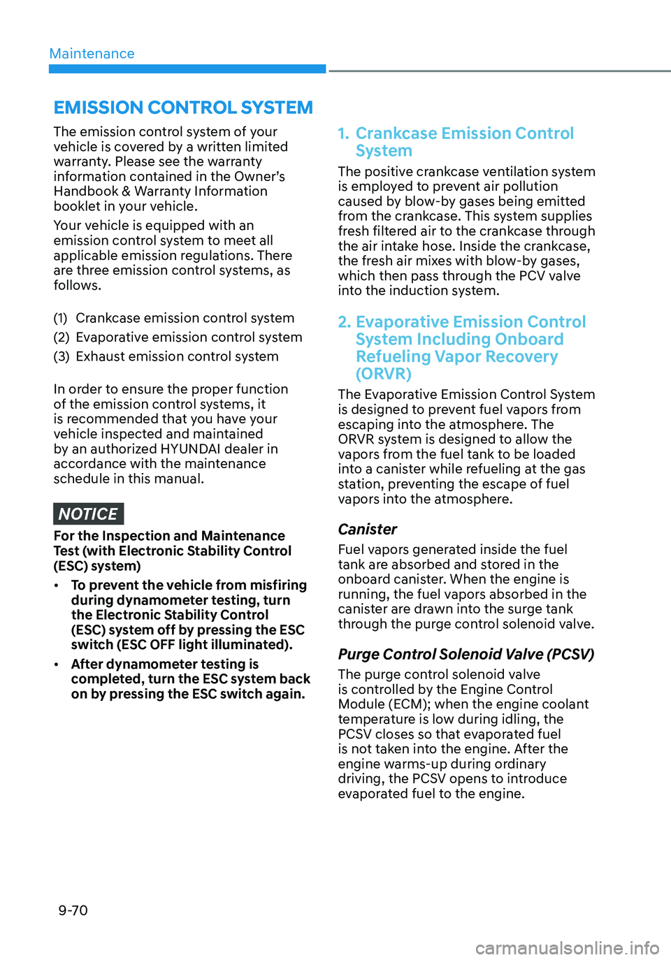
The emission control system of your
vehicle is covered by a written limited
warranty. Please see the warranty
information contained in the Owner’s
Handbook & Warranty Information
booklet in your vehicle.
Your vehicle is equipped with an
emission control system to meet all
applicable emission regulations. There
are three emission control systems, as
follows.
(1) Crankcase emission control system
(2) Evaporative emission control system
(3) Exhaust emission control system
In order to ensure the proper function
of the emission control systems, it
is recommended that you have your
vehicle inspected and maintained
by an authorized HYUNDAI dealer in
accordance with the maintenance
schedule in this manual.
NOTICE
For the Inspection and Maintenance
Test (with Electronic Stability Control
(ESC) system)
• To prevent the vehicle from misfiring
during dynamometer testing, turn
the Electronic Stability Control
(ESC) system off by pressing the ESC
switch (ESC OFF light illuminated).
• After dynamometer testing is
completed, turn the ESC system back
on by pressing the ESC switch again.
1. Crankcase Emission Control
System
The positive crankcase ventilation system
is employed to prevent air pollution
caused by blow-by gases being emitted
from the crankcase. This system supplies
fresh filtered air to the crankcase through
the air intake hose. Inside the crankcase,
the fresh air mixes with blow-by gases,
which then pass through the PCV valve
into the induction system.
2. Evaporative Emission Control
System Including Onboard
Refueling Vapor Recovery
(ORVR)
The Evaporative Emission Control System
is designed to prevent fuel vapors from
escaping into the atmosphere. The
ORVR system is designed to allow the
vapors from the fuel tank to be loaded
into a canister while refueling at the gas
station, preventing the escape of fuel
vapors into the atmosphere.
Canister
Fuel vapors generated inside the fuel
tank are absorbed and stored in the
onboard canister. When the engine is
running, the fuel vapors absorbed in the
canister are drawn into the surge tank
through the purge control solenoid valve.
Purge Control Solenoid Valve (PCSV)
The purge control solenoid valve
is controlled by the Engine Control
Module (ECM); when the engine coolant
temperature is low during idling, the
PCSV closes so that evaporated fuel
is not taken into the engine. After the
engine warms-up during ordinary
driving, the PCSV opens to introduce
evaporated fuel to the engine.
EMISSION CONTROL SYSTEM
Page 541 of 555
Maintenance
9-72
Operating precautions for catalytic
converters (if equipped)
WARNING
The exhaust system and catalytic
converter are very hot during and
immediately after the engine has been
running. To avoid SERIOUS INJURY or
DEATH:
• Do not park, idle, or drive the vehicle
over or near flammable objects, such
as grass, vegetation, paper, leaves,
etc. A hot exhaust system can ignite
flammable items under your vehicle.
• Keep away from the exhaust system
and catalytic converter or you may
get burned.
Also, do not remove the heat sink
around the exhaust system, do not
seal the bottom of the vehicle, and
do not coat the vehicle for corrosion
control. It may present a fire risk
under certain conditions. Your vehicle is equipped with a catalytic
converter emission control device.
To prevent damage to the catalytic
converter and to your vehicle, take the
following precautions:
•
Use only UNLEADED FUEL for
gasoline engines.
• Do not operate the vehicle when
there are signs of engine malfunction,
such as misfire or a noticeable loss of
performance.
• Do not misuse or abuse the engine.
Examples of misuse are coasting with
the engine off and descending steep
grades in gear with the engine off.
• Do not operate the engine at high
idle speed for extended periods (5
minutes or more).
• Do not modify or tamper with any
part of the engine or emission
control system. All inspections and
adjustments must be made by an
authorized HYUNDAI dealer.
• Avoid driving with extremely low
fuel level. If you run out of gasoline,
it could cause the engine to misfire
and result in excessive loading of the
catalytic converter.
Page 547 of 555

I
I-5
E
Emission Control System
........................................................................\
............9-70
Engine Compartment
........................................................................\
.............2-6/ 9-3
Engine coolant/Inverter coolant
........................................................................\
...9-18
Changing Engine Coolant ........................................................................\
........9-21
Checking the Coolant Level ........................................................................\
.....9-18
Engine Number
........................................................................\
............................2-14
Engine Oil
........................................................................\
....................................9-16
Checking the Engine Oil and Filter ..................................................................9-17
Checking the Engine Oil Level ........................................................................\
9-16
Engine specification ........................................................................\
....................... 2-7
Explanation of Scheduled Maintenance Items
....................................................9-14
Dual clutch transmission fluid ........................................................................\
.9-15
HSG (Hybrid Starter & Generator) Belt .........................................................9-14
Exterior Lights
........................................................................\
.............................5-72
Battery saver function ........................................................................\
..............5-75
Headlamp delay function ........................................................................\
.........5-75
High beam operation ........................................................................\
................5-73
Lighting control ........................................................................\
........................5-72
Turn signals and lane change signals ...............................................................5-74
Exterior Overview
........................................................................\
.........................2-2
F
Forward Collision–Avoidance Assist (FCA) (front view camera only)
................7-2
Function malfunction and limitations ................................................................7-7
Function operation ........................................................................\
......................7-5
Function settings ........................................................................\
........................7-3
Forward Collision–Avoidance Assist (FCA) (sensor fusion)
.............................7-14
Function malfunction and limitations ..............................................................7-22
Function operation ........................................................................\
....................7-18
Function settings ........................................................................\
......................7-16
Fuel filler door
........................................................................\
.............................5-69
Fuel Requirements
........................................................................\
.........................1-5
Fuses
........................................................................\
............................................9-42
Engine Compartment Panel Fuse Replacement ...............................................9-44
Fuse/Relay Panel Description ........................................................................\
..9-45
Instrument Panel Fuse Replacement ................................................................9-43