2021 ALFA ROMEO STELVIO brake light
[x] Cancel search: brake lightPage 128 of 280
STARTING AND OPERATING
126
(Continued)
ParkSense System Usage Precautions
NOTE:
Some conditions may influence the perfor-
mance of the ParkSense system:
Reduced sensor sensitivity could be due to
the presence of ice, snow, mud, or thick
paint on the surface of the sensor.
The sensors may detect a false obstacle
(echo interference) due to mechanical inter -
ference, for example when washing the
vehicle or in extreme weather.
The signals sent by the sensors can be
altered by the presence of ultrasonic
systems (e.g. pneumatic brake systems of
trucks or pneumatic drills) near the vehicle.
System performance can be influenced by
the position of the sensors. For example,
due to a change in the ride setting (caused
by wear to the shock absorbers or suspen -
sion), by changing tires, overloading the
vehicle or operations that require the
vehicle to be lowered.
Be sure not to place bumper stickers or
other adhesives over the sensors as this will
affect system performance.
The presence of a trailer hitch without a
trailer. This may interfere with the operation
of the parking sensors. Before using the
ParkSense system, it is recommended to remove or close the trailer hitch assembly
when the vehicle is not being used for
towing.
LANE DEPARTURE WARNING
(LDW) SYSTEM
Lane Departure Warning Operation
The Lane Departure Warning system uses a
forward looking camera located on the wind
-
shield to detect lane markings and measure
vehicle position within the lane boundaries.
When one or both lane limits are detected and
the vehicle passes over one without an acti -
vated turn signal, the system emits a visual as
well as an acoustic signal.
If the vehicle continues to go beyond the line
of the lane without any intervention from the
driver, the surpassed line will light up on the
display (left or right) to urge the driver to bring
the vehicle back into the limits of the lane.
CAUTION!
Projecting loads on the roof of the vehicle
may interfere with the correct operation of
the camera. Before starting, make sure
the load is correctly positioned in order
not to cover the camera operating range.
Do not cover the operating range of the
camera with stickers or other objects.
Do not tamper with nor operate on the
camera. Do not close the openings in the
aesthetic cover located under the interior
rearview mirror. In the event of a failure of
the camera, contact your authorized
dealer.
The camera may have limited or absent
operation due to weather conditions such
as: heavy rain, hail, thick fog, heavy snow,
formation of ice layers on the windshield.
Camera operation may also be compro -
mised by the presence of dust, condensa -
tion, dirt or ice on the windshield, by traffic
conditions (e.g. vehicles that are driving
not aligned with yours, vehicle driving in a
transverse or opposite way on the same
lane, bend with a small radius of curva -
ture), by road surface conditions and by
driving conditions (e.g. off-road driving).
Make sure the windshield is always clean.
Use specific detergents and clean cloths
to avoid scratching the windshield. The
camera operation may also be limited or
absent in some driving, traffic and road
surface conditions.
If the windshield must be replaced due to
scratches, chipping or breakage, contact
exclusively an authorized dealer. Do not
replace the windshield on your own. It is
advisable to replace the windshield if it is
damaged in the area of the camera.
CAUTION! (Continued)
21_GU_OM_EN_USC_t.book Page 126
Page 142 of 280
STARTING AND OPERATING
140
Towing Requirements — Trailer Brakes
Do not interconnect the hydraulic brake
system or vacuum system of your vehicle
with that of the trailer. This could cause
inadequate braking and possible personal
injury.
An electronically actuated trailer brake
controller is required when towing a trailer
with electronically actuated brakes. When
towing a trailer equipped with a hydraulic
surge actuated brake system, an electronic
brake controller is not required.
Trailer brakes are recommended for trailers
over 1,000 lbs (453 kg) and required for
trailers in excess of 2,000 lbs (907 kg).
Towing Requirements — Trailer Lights And
Wiring
Whenever you pull a trailer, regardless of the
trailer size, stoplights and turn signals on the
trailer are required for motoring safety.
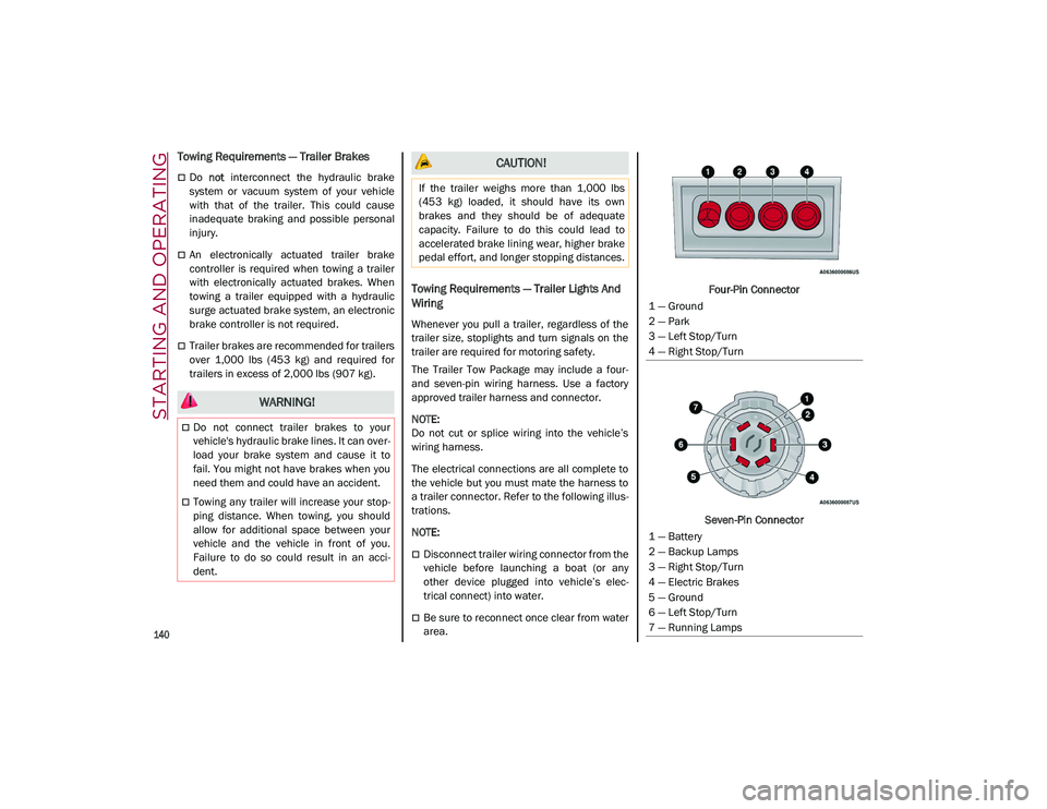
The Trailer Tow Package may include a four-
and seven-pin wiring harness. Use a factory
approved trailer harness and connector.
NOTE:
Do not cut or splice wiring into the vehicle’s
wiring harness.
The electrical connections are all complete to
the vehicle but you must mate the harness to
a trailer connector. Refer to the following illus -
trations.
NOTE:
Disconnect trailer wiring connector from the
vehicle before launching a boat (or any
other device plugged into vehicle’s elec -
trical connect) into water.
Be sure to reconnect once clear from water
area. Four-Pin Connector
Seven-Pin Connector
WARNING!
Do not connect trailer brakes to your
vehicle's hydraulic brake lines. It can over -
load your brake system and cause it to
fail. You might not have brakes when you
need them and could have an accident.
Towing any trailer will increase your stop -
ping distance. When towing, you should
allow for additional space between your
vehicle and the vehicle in front of you.
Failure to do so could result in an acci -
dent.
CAUTION!
If the trailer weighs more than 1,000 lbs
(453 kg) loaded, it should have its own
brakes and they should be of adequate
capacity. Failure to do this could lead to
accelerated brake lining wear, higher brake
pedal effort, and longer stopping distances.
1 — Ground
2 — Park
3 — Left Stop/Turn
4 — Right Stop/Turn
1 — Battery
2 — Backup Lamps
3 — Right Stop/Turn
4 — Electric Brakes
5 — Ground
6 — Left Stop/Turn
7 — Running Lamps
21_GU_OM_EN_USC_t.book Page 140
Page 145 of 280
143
Traffic And Road Conditions
High fuel consumption is caused by heavy
traffic, for instance when traveling in traffic
with frequent use of low gears or in cities with
many traffic lights. Winding mountain roads
and rough road surfaces also adversely affect
consumption.
Stops In Traffic
During prolonged stops (e.g. railway cross-
ings), turn off the engine.
Performance — Quadrifoglio
This vehicle is equipped with an engine
capable of delivering exceptionally fast accel -
eration and speed:
Peak power: 505 HP at 6,500 RPM.
Peak torque: 443 ft-lbs at 2,500–5,000 RPM.
Top speed: 176 mph (283 km/h).
Acceleration from 0 to 60 mph (0 to 100 km/h):
3.6 seconds.
For safe driving, it is essential, particularly
during the first days of use, to get to know the
car by driving carefully and gradually discov -
ering its performance.
Brakes
The car braking system may be available with
four carbon-ceramic material brake discs, one
on each wheel. In order to guarantee the maximum braking
capacity for the first use, Alfa Romeo performs
a "run-in" procedure for discs and pads directly
at the factory.
The use of carbon-ceramic material brake
discs guarantees braking features (better
deceleration/pedal load ratio, braking
distances, fading resistance) proportional to
the dynamic features of the car in addition to
considerably decreasing the unsprung compo
-
nent weight.
The materials used and the structural features
of the system could generate unusual noises
which have absolutely no adverse effect on
correct operation and reliability of the braking
system.
Greater pressure may need to be applied to
the brake pedal the first time to keep the same
braking capacities in presence of condensa -
tion or salt on the braking surfaces, for
example after washing or if the car is not used
for a long time.
NOTE:
Given the high technological level of this
system, any servicing on it must be performed
by an authorized dealer which exclusively has
the skills needed for the repair and mainte -
nance operations. In case of intensive, high-performance use of
the car, have the efficiency of the
carbon-ceramic material braking system
inspected as shown on the Maintenance Plan
at an authorized dealer.
Driving On Race Tracks
Before driving on a track using a racing style, it
is necessary to:
Attend a race track driving course.
Check the liquid levels in the engine
compartment
Ú
page 208.
Have the car inspected at an authorized
dealer.
Remember that the car was not designed to be
driven exclusively on the race track and that
this use increases stress and component
wear.
NOTE:
Quadrifoglio front brakes are equipped with
Non-Asbestos Organic (NAO) type pads. These
pads are NOT suitable for high thermal loads
(for example track use). If you want to use
vehicle on a track it is recommended to use
the optional CCM Brakes (Carbon Ceramic
Brake disc).
21_GU_OM_EN_USC_t.book Page 143
Page 147 of 280
145
(Continued)
SAFETY
This very important section describes the
safety systems that your vehicle may be
equipped with, and provides instructions on
how to use them correctly.
ACTIVE SAFETY SYSTEMS
The vehicle may be equipped with the
following active safety devices:
Anti-Lock Brake System (ABS)
Active Torque Vectoring (ATV) System
Dynamic Steering Torque (DST) System
Drive Train Control (DTC) System
Electronic Stability Control (ESC) System
Hill Descent Control (HDC) System
Hill Start Assist (HSA) System
Panic Brake Assist (PBA) System
Traction Control System (TCS)
For system operation, see the following pages.
Anti-Lock Brake System (ABS)
An integral part of the braking system, the ABS
prevents one or more wheels from locking and
slipping in all road surface conditions, regard -
less of the intensity of the braking action. The
system ensures that the vehicle can be
controlled even during emergency braking,
allowing the driver to optimize stopping
distances. The system intervenes during braking when
the wheels are about to lock, typically in emer
-
gency braking or low-grip conditions where
locking may be more frequent.
The system also improves control and stability
of the vehicle when braking on a surface
where the grip of the left and right wheels
varies, such as in a corner.
The Electronic Braking Force Distribution
(EBD) system works with the ABS, allowing the
brake force to be distributed between the front
and rear wheels.
System Intervention
The ABS equipped on this vehicle is provided
with the "Brake-By-Wire", Integrated Brake
System (IBS), function. With this system, the
command given by pressing the brake pedal is
not transmitted hydraulically, but electrically.
Therefore, the light pulsation that is felt on the
pedal with the traditional system is no longer
noticeable.Active Torque Vectoring (ATV) System — If
Equipped
The dynamic drive control is used to optimize
and balance the drive torque between the
wheels of the same axles. The ATV system
improves the grip in turns, sending more drive
torque to the external wheel.
WARNING!
The ABS contains sophisticated electronic
equipment that may be susceptible to
interference caused by improperly
installed or high output radio transmitting
equipment. This interference can cause
possible loss of anti-lock braking capa -
bility. Installation of such equipment
should be performed by qualified profes -
sionals.
Pumping of the Anti-Lock Brakes will
diminish their effectiveness and may lead
to a collision. Pumping makes the stop -
ping distance longer. Just press firmly on
your brake pedal when you need to slow
down or stop.
The ABS cannot prevent the natural laws
of physics from acting on the vehicle, nor
can it increase braking or steering effi -
ciency beyond that afforded by the condi -
tion of the vehicle brakes and tires or the
traction afforded.
The ABS cannot prevent collisions,
including those resulting from excessive
speed in turns, following another vehicle
too closely, or hydroplaning.
The capabilities of an ABS equipped
vehicle must never be exploited in a reck -
less or dangerous manner that could jeop -
ardize the user’s safety or the safety of
others.
WARNING! (Continued)
21_GU_OM_EN_USC_t.book Page 145
Page 148 of 280
SAFETY
146
Given that, in a turn, the external wheels of the
car travel more than the internal ones and
therefore turn faster, sending a higher thrust
to the external rear wheel allows for the car to
be more stable and to not suffer an "under-
steer" condition. Understeer occurs when the
vehicle is turning less than appropriate for the
steering wheel position.
Dynamic Steering Torque (DST) System
DST uses the integration of the Electronic
Stability Control (ESC) system with the electric
power steering to increase the safety level of
the whole vehicle.
In critical situations (e.g. braking on surfaces
with different grip conditions), the ESC system
influences the steering through the DST func -
tion to implement an additional torque contri -
bution on the steering wheel in order to
suggest the most correct maneuver to the
driver.
The coordinated action of the brakes and
steering increases the safety and control of
the vehicle.
NOTE:
The DST feature is only meant to help the
driver realize the correct course of action
through small torques on the steering wheel,
which means the effectiveness of the DST
feature is highly dependent on the driver’s
sensitivity and overall reaction to the applied
torque. It is very important to realize that this feature will not steer the vehicle, meaning the
driver is still responsible for steering the
vehicle.
Drive Train Control (DTC) System
Some models of this vehicle are equipped with
an All-Wheel Drive (AWD) system, which offers
an optimal drive for countless driving condi
-
tions and road surfaces. The system reduces
tire slipping to a minimum, automatically
redistributing the torque to the front and rear
wheels as needed.
To maximize fuel savings, the vehicle with
AWD automatically passes to Rear-Wheel
Drive (RWD) when the road and environmental
conditions are such that they wouldn't cause
the tires to slip. When the road and environ -
mental conditions require better traction, the
vehicle automatically switches to AWD mode.
NOTE:
There may be a brief delay in shifting to
AWD mode after a tire slipping event occurs.
If the system failure symbol switches on,
after starting the engine or while driving, it
means that the AWD system is not working
properly. If the warning message activates
frequently, it is recommended to carry out
the maintenance operations.
Electronic Stability Control (ESC) System
The ESC system improves the directional
control and stability of the vehicle in various
driving conditions.
The ESC system corrects the vehicle’s under -
steer and oversteer, distributing the brake
force on the appropriate wheels. The torque
supplied by the engine can also be reduced in
order to maintain control of the vehicle.
The ESC system uses sensors installed on the
vehicle to determine the path that the driver
intends to follow and compares it with the
vehicle’s effective path. When the real path
deviates from the desired path, the ESC
system intervenes to counter the vehicle’s
oversteer or understeer.
Oversteer occurs when the vehicle is
turning more than it should according to the
angle of the steering wheel.
Understeer occurs when the vehicle is
turning less than it should according to the
angle of the steering wheel.
System Intervention
The intervention of the system is indicated by
the flashing of the ESC warning light on the
instrument panel, to inform the driver that the
vehicle stability and grip are critical.
21_GU_OM_EN_USC_t.book Page 146
Page 151 of 280
149
Panic Brake Assist (PBA) System
The PBA system is designed to improve the
vehicle’s braking capacity during emergency
braking.
The system detects emergency braking by
monitoring the speed and force with which the
brake pedal is pressed, and consequently
applies the optimal brake pressure. This can
reduce the braking distance: the PBA system
therefore complements the ABS.
Maximum assistance from the PBA system is
obtained by pressing the brake pedal very
quickly. In addition, the brake pedal should be
pressed continuously during braking, avoiding
intermittent presses, to get the most out of thesystem. Do not reduce pressure on the brake
pedal until braking is no longer necessary.
The PBA system is deactivated when the brake
pedal is released.Traction Control System (TCS)
The TCS automatically operates in the event of
slipping, loss of grip on wet roads (hydro
-
planing), and acceleration on one or both drive
wheels on roads that are slippery, snowy, icy,
etc. Depending on the slipping conditions, two
different control systems are activated:
If the slipping involves both drive wheels,
the system intervenes, reducing the power
transmitted by the engine.
If the slipping only involves one of the drive
wheels, the Brake Limited Differential (BLD)
function is activated, automatically braking the wheel which is slipping (the behavior of
a self-locking differential is simulated). This
will increase the engine torque transferred
to the wheel which isn't slipping.
System Intervention
The intervention of the system is indicated by
the flashing of the ESC warning light on the
instrument panel, to inform the driver that the
vehicle stability and grip are critical.
AUXILIARY DRIVING SYSTEMS
The following auxiliary driving systems are
available in this vehicle:
Blind Spot Monitoring (BSM) — if equipped
Active Blind Spot Assist (ABSA) — if
equipped
Forward Collision Warning Plus (FCW+)
Tire Pressure Monitoring System (TPMS)
The vehicle may also be fitted with the
following driving assistance systems:
Driver Attention Assist (DAA)
Lane Departure Warning (LDW)
Lane Keeping Assist (LKA)
Highway Assist System (HAS)
Traffic Jam Assist (TJA)
Adaptive Cruise Control (ACC)
Intelligent Speed Control (ISC)
Traffic Sign Recognition (TSR)
WARNING!
There may be situations where the Hill Start
Assist (HSA) will not activate and slight
rolling may occur, such as on minor hills or
with a loaded vehicle, or while pulling a
trailer. HSA is not a substitute for active
driving involvement. It is always the driver’s
responsibility to be attentive to distance to
other vehicles, people, and objects, and
most importantly brake operation to ensure
safe operation of the vehicle under all road
conditions. Your complete attention is
always required while driving to maintain
safe control of your vehicle. Failure to follow
these warnings can result in a collision or
serious personal injury.
WARNING!
The Panic Brake Assist (PBA) cannot
prevent the natural laws of physics from
acting on the vehicle, nor can it increase
the traction afforded by prevailing road
conditions. PBA cannot prevent collisions,
including those resulting from excessive
speed in turns, driving on very slippery
surfaces, or hydroplaning. The capabilities
of a PBA-equipped vehicle must never be
exploited in a reckless or dangerous
manner, which could jeopardize the user's
safety or the safety of others.
21_GU_OM_EN_USC_t.book Page 149
Page 154 of 280
SAFETY
152
Operating Mode
The system may be activated/deactivated via
the radio system. To access the function,
select the following items on the main menu in
sequence:
1. “Driving Assistance”
2. “Blind Spot Alert”
“Blind Spot Alert”, “Visual” Mode
When the system is enabled, the warning light
within the door mirror on the side of the
detected object illuminates.
The visual warning on the mirror will blink if the
driver activates the turn signals, indicating a
lane change.
The warning light will be constant if the driver
stays in the same lane.
“Blind Spot Alert” Function Deactivation
When the system is deactivated (“Blind Spot
Alert” mode off), the BSM or RCP systems will
not emit an audible or a visual warning.
The BSM system will store the operating mode
that was active when the engine was stopped.
Each time the engine is started, the operating
mode stored previously will be recalled and
used
Ú
page 268.
Active Blind Spot Assist (ABSA) System — If
Equipped
The ABSA system is to help avoid/limit lateral
collisions with cars coming from adjacent lanes changing the vehicle’s trajectory in order
to try to keep it in the detected lane.
The system warns the driver about the pres
-
ence of other vehicles in the detection area by
illuminating the warning light located within
the door mirror on the side in which the other
vehicle was detected and by means of an
acoustic signal and/or vibration on the
steering wheel and/or counter-steering torque
on the steering wheel (if the respective item on
the “Driver Assistance” menu is set up and
then “Safety” is selected on the radio system).
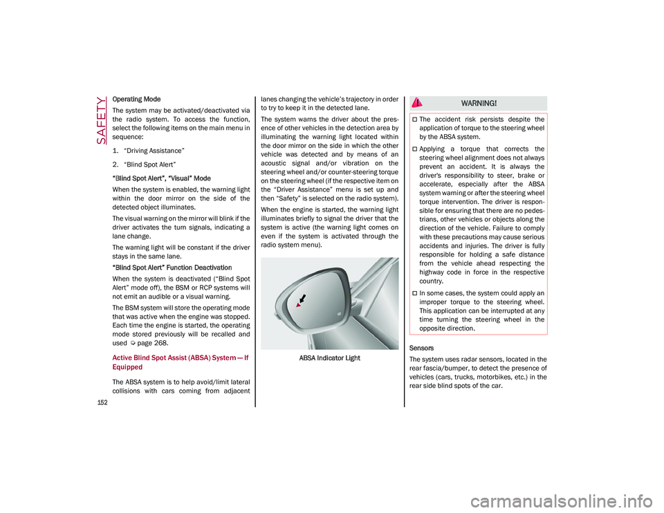
When the engine is started, the warning light
illuminates briefly to signal the driver that the
system is active (the warning light comes on
even if the system is activated through the
radio system menu).
ABSA Indicator Light Sensors
The system uses radar sensors, located in the
rear fascia/bumper, to detect the presence of
vehicles (cars, trucks, motorbikes, etc.) in the
rear side blind spots of the car.
WARNING!
The accident risk persists despite the
application of torque to the steering wheel
by the ABSA system.
Applying a torque that corrects the
steering wheel alignment does not always
prevent an accident. It is always the
driver's responsibility to steer, brake or
accelerate, especially after the ABSA
system warning or after the steering wheel
torque intervention. The driver is respon
-
sible for ensuring that there are no pedes -
trians, other vehicles or objects along the
direction of the vehicle. Failure to comply
with these precautions may cause serious
accidents and injuries. The driver is fully
responsible for holding a safe distance
from the vehicle ahead respecting the
highway code in force in the respective
country.
In some cases, the system could apply an
improper torque to the steering wheel.
This application can be interrupted at any
time turning the steering wheel in the
opposite direction.
21_GU_OM_EN_USC_t.book Page 152
Page 159 of 280
157
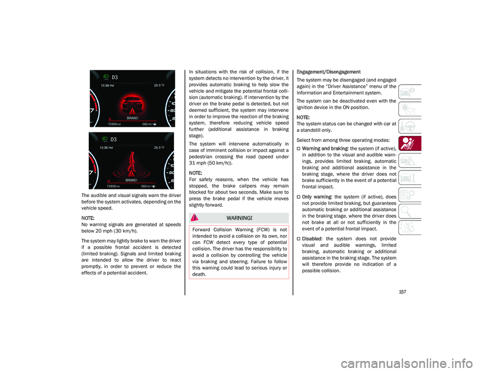
The audible and visual signals warn the driver
before the system activates, depending on the
vehicle speed.
NOTE:
No warning signals are generated at speeds
below 20 mph (30 km/h).The system may lightly brake to warn the driver
if a possible frontal accident is detected
(limited braking). Signals and limited braking
are intended to allow the driver to react
promptly, in order to prevent or reduce the
effects of a potential accident. In situations with the risk of collision, if the
system detects no intervention by the driver, it
provides automatic braking to help slow the
vehicle and mitigate the potential frontal colli
-
sion (automatic braking). If intervention by the
driver on the brake pedal is detected, but not
deemed sufficient, the system may intervene
in order to improve the reaction of the braking
system, therefore reducing vehicle speed
further (additional assistance in braking
stage).
The system will intervene automatically in
case of imminent collision or impact against a
pedestrian crossing the road (speed under
31 mph (50 km/h)).
NOTE:
For safety reasons, when the vehicle has
stopped, the brake calipers may remain
blocked for about two seconds. Make sure to
press the brake pedal if the vehicle moves
slightly forward. Engagement/Disengagement
The system may be disengaged (and engaged
again) in the “Driver Assistance” menu of the
Information and Entertainment system.
The system can be deactivated even with the
ignition device in the ON position.
NOTE:
The system status can be changed with car at
a standstill only.
Select from among three operating modes:
Warning and braking
: the system (if active),
in addition to the visual and audible warn -
ings, provides limited braking, automatic
braking and additional assistance in the
braking stage, where the driver does not
brake sufficiently in the event of a potential
frontal impact.
Only warning : the system (if active), does
not provide limited braking, but guarantees
automatic braking or additional assistance
in the braking stage, where the driver does
not brake at all or not sufficiently in the
event of a potential frontal impact.
Disabled : the system does not provide
visual and audible warnings, limited
braking, automatic braking or additional
assistance in the braking stage. The system
will therefore provide no indication of a
possible collision.
WARNING!
Forward Collision Warning (FCW) is not
intended to avoid a collision on its own, nor
can FCW detect every type of potential
collision. The driver has the responsibility to
avoid a collision by controlling the vehicle
via braking and steering. Failure to follow
this warning could lead to serious injury or
death.
21_GU_OM_EN_USC_t.book Page 157