2021 ALFA ROMEO STELVIO suspension
[x] Cancel search: suspensionPage 120 of 280

STARTING AND OPERATING
118
Automatic Deactivation
System operation will be temporarily disabled
under the following conditions:
When traveling around narrow bends
If the lane boundaries are not detected
One of the two lines is interrupted
The sun is low and reflects on the radar
camera
If the turn signals are activated
If the driver intentionally changes lanes
without using the turn signal
If manual steering begins
If the driver’s hands are removed from the
steering wheel
When there is no surrounding traffic and
there are no horizontal lane boundaries
If the system is not functioning properly
If lateral acceleration is high
NOTE:
When TJA is turned off, the symbol in the
instrument cluster display will turn red, and
then grey.
A sensor in the steering wheel detects
whether the driver’s hands are placed on
the steering wheel. When the automatic suspension conditions
are over, the TJA system will be automatically
reactivated.
Operation
The TJA system can only operate when the
driver’s hands are on the steering wheel.
If the system detects that the driver’s hands
have been removed from the steering wheel, a
message will appear in the instrument cluster
display to alert the driver to place their hands
back on the wheel.
NOTE:
If the vehicle begins to cross the lane
boundary, the steering wheel will vibrate
and a dedicated screen will appear in the
instrument cluster display.
The TJA system may take up to five seconds
to become active once all conditions are
met.
The following conditions must be met in order
to activate the system:
The TJA system must be enabled
The Adaptive Cruise Control (ACC) system
must be turned on
The right and left lane boundaries must be
recognized by the system
The vehicle must be traveling at a speed
between 0 and 37 mph (0 and 60 km/h)
The camera, radar, and radio system must
be functioning properly
The road lane width must be between 8.5 ft
and 13.7 ft (2.6 m and 4.2 m)
The turn signals must be turned off
The TJA system must be functioning prop -
erly
If the ACC speed is set to 37 mph (60 km/h)
or less, traveling downhill may increase the
vehicle speed. The system will remain inac -
tive until the speed returns to 37 mph
(60 km/h) or less.
Indications On The Display
The TJA system status is indicated by the color
of the symbol in the instrument cluster display.
The system uses sensors in the steering wheel
to detect if the driver’s hands are present. If
the driver’s hands are removed, a series of
warnings will appear in the instrument cluster
display to alert the driver to reposition their
hands on the steering wheel. Acoustic signals
will also be emitted.
If the driver’s hands are not returned to the
steering wheel after a period of time, the
system will be disabled.
21_GU_OM_EN_USC_t.book Page 118
Page 138 of 280

STARTING AND OPERATING
136
Gross Vehicle Weight Rating (GVWR)
The GVWR is the total permissible weight of
your vehicle including driver, passengers,
vehicle, options and cargo. The label also
specifies maximum capacities of front and
rear axle systems (GAWR). Total load must be
limited so GVWR and front and rear GAWR are
not exceeded.
Payload
The payload of a vehicle is defined as the
allowable load weight a truck can carry,
including the weight of the driver, all passen-
gers, options and cargo.
Gross Axle Weight Rating (GAWR)
The GAWR is the maximum permissible load
on the front and rear axles. The load must be
distributed in the cargo area so that the GAWR
of each axle is not exceeded.
Each axle GAWR is determined by the compo -
nents in the system with the lowest load
carrying capacity (axle, springs, tires or
wheels). Heavier axles or suspension compo -
nents sometimes specified by purchasers for
increased durability do not necessarily
increase the vehicle's GVWR.
Tire Size
The tire size on the Vehicle Certification Label
represents the actual tire size on your vehicle.
Replacement tires must be equal to the load
capacity of this tire size.
Rim Size
This is the rim size that is appropriate for the
tire size listed.
Inflation Pressure
This is the cold tire inflation pressure for your
vehicle for all loading conditions up to full
GAWR.
Curb Weight
The curb weight of a vehicle is defined as the
total weight of the vehicle with all fluids,
including vehicle fuel, at full capacity condi -
tions, and with no occupants or cargo loaded
into the vehicle. The front and rear curb weight
values are determined by weighing your
vehicle on a commercial scale before any
occupants or cargo are added.
Loading
The actual total weight and the weight of the
front and rear of your vehicle at the ground can
best be determined by weighing it when it is
loaded and ready for operation.
The entire vehicle should first be weighed on a
commercial scale to ensure that the GVWR
has not been exceeded. The weight on the
front and rear of the vehicle should then be
determined separately to be sure that the load
is properly distributed over the front and rear
axle. Weighing the vehicle may show that the
GAWR of either the front or rear axles has
been exceeded but the total load is within the specified GVWR. If so, weight must be shifted
from front to rear or rear to front as appro
-
priate until the specified weight limitations are
met. Store the heavier items down low and be
sure that the weight is distributed equally.
Stow all loose items securely before driving.
Improper weight distributions can have an
adverse effect on the way your vehicle steers
and handles and the way the brakes operate.
TRAILER TOWING
In this section you will find safety tips and
information on limits to the type of towing you
can reasonably do with your vehicle. Before
towing a trailer, carefully review this informa -
tion to tow your load as efficiently and safely
as possible.
To maintain the New Vehicle Limited Warranty
coverage, follow the requirements and recom -
mendations in this manual concerning vehi -
cles used for trailer towing.
CAUTION!
Do not load your vehicle any heavier than
the GVWR or the maximum front and rear
GAWR. If you do, parts on your vehicle can
break, or it can change the way your vehicle
handles. This could cause you to lose
control. Also overloading can shorten the
life of your vehicle.
21_GU_OM_EN_USC_t.book Page 136
Page 149 of 280

147
Hill Descent Control (HDC) System — If
Equipped
The HDC function is an integral part of the
Electronic Stability Control (ESC) system,
keeping the vehicle at a constant speed while
descending a hill by actively controlling the
brakes.
HDC aims to create vehicle stability and safer
driving in various situations, including poor
grip conditions and steep descents.
The system has three different modes:
Off: the system is deactivated
Enabled: the system is enabled and ready to
intervene when the activation conditions
are met
Active: the system actively controls the
vehicle speed
Enabling The System
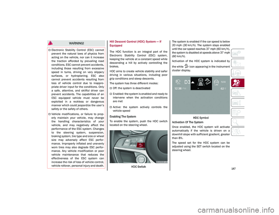
To enable the system, push the HDC switch
located on the steering wheel.
HDC Switch The system is enabled if the car speed is below
20 mph (30 km/h). The system stays enabled
until the car speed reaches 37 mph (60 km/h),
the system is disabled at speeds above 37 mph
(60 km/h).
Activation of the HDC system is indicated by
the white icon appearing in the instrument
cluster display.
HDC Symbol
Activation Of The System
Once enabled, the HDC system will activate
automatically if the vehicle is driven on a
downhill slope with sufficient gradient, greater
than 8%.
The speed set for the HDC system can be
adjusted using the SET switch located on the
steering wheel.
WARNING!
Electronic Stability Control (ESC) cannot
prevent the natural laws of physics from
acting on the vehicle, nor can it increase
the traction afforded by prevailing road
conditions. ESC cannot prevent accidents,
including those resulting from excessive
speed in turns, driving on very slippery
surfaces, or hydroplaning. ESC also
cannot prevent accidents resulting from
loss of vehicle control due to inappro -
priate driver input for the conditions. Only
a safe, attentive, and skillful driver can
prevent accidents. The capabilities of an
ESC equipped vehicle must never be
exploited in a reckless or dangerous
manner which could jeopardize the user’s
safety or the safety of others.
Vehicle modifications, or failure to prop -
erly maintain your vehicle, may change
the handling characteristics of your
vehicle, and may negatively affect the
performance of the ESC system. Changes
to the steering system, suspension,
braking system, tire type and size or wheel
size may adversely affect ESC perfor-
mance. Improperly inflated and unevenly
worn tires may also degrade ESC perfor -
mance. Any vehicle modification or poor
vehicle maintenance that reduces the
effectiveness of the ESC system can
increase the risk of loss of vehicle control,
vehicle rollover, personal injury and death.
21_GU_OM_EN_USC_t.book Page 147
Page 207 of 280

205
(Continued)
MANUAL PARK RELEASE
See an authorized dealer to disengage the
manual park release lever.
TOWING A DISABLED VEHICLE
This section describes procedures for towing a
disabled vehicle using a commercial towing
service.
NOTE:
If your vehicle is equipped with a Anti-Lift
Protection system, you will need to disable the
system prior to towing by pushing the button
located on the overhead console
Ú
page 23.
The operators of the assistance vehicle must
be informed with regard to the vehicle's
minimum height from ground in order to avoid
contact between the ends of the bumpers with
the equipment of the breakdown truck.
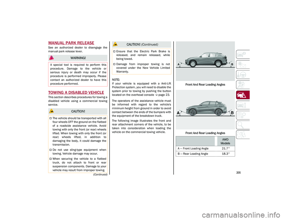
The following image illustrates the front and
rear attachment corners of the vehicle, to be
taken into consideration when loading the
vehicle on the commercial towing vehicle. Front And Rear Loading Angles
Front And Rear Loading Angles
WARNING!
A special tool is required to perform this
procedure. Damage to the vehicle or
serious injury or death may occur if the
procedure is performed improperly. Please
contact an authorized dealer to have this
procedure performed.
CAUTION!
The vehicle should be transported with all
four wheels OFF the ground on the flatbed
of a roadside assistance vehicle. Avoid
towing with only the front (or rear) wheels
lifted. When towing with only the front (or
rear) wheels lifted, in addition to
damaging the body, it could damage the
transmission.
Do not use sling-type equipment when
towing. Vehicle damage may occur.
When securing the vehicle to a flatbed
truck, do not attach to front or rear
suspension components. Damage to your
vehicle may result from improper towing.
Ensure that the Electric Park Brake is
released, and remain released, while
being towed.
Damage from improper towing is not
covered under the New Vehicle Limited
Warranty.
CAUTION! (Continued)
AWD
Models
A — Front Loading Angle 21.7°
B — Rear Loading Angle 18.3°
21_GU_OM_EN_USC_t.book Page 205
Page 246 of 280

SERVICING AND MAINTENANCE
244
NOTE:
Wheel valve stem must be replaced as well
when installing new tires due to wear and tear
in existing tires.
Keep dismounted tires in a cool, dry place with
as little exposure to light as possible. Protect
tires from contact with oil, grease, and gaso-
line.
Replacement Tires
The tires on your new vehicle provide a
balance of many characteristics. They should
be inspected regularly for wear and correct
cold tire inflation pressures. The manufacturer
strongly recommends that you use tires equiv -
alent to the originals in size, quality and perfor -
mance when replacement is needed
Ú
page 243. Refer to the Tire and Loading
Information placard or the Vehicle Certifica -
tion Label for the size designation of your tire.
The Load Index and Speed Symbol for your tire
will be found on the original equipment tire
sidewall.
See the Tire Sizing Chart example for more
information relating to the Load Index and
Speed Symbol of a tire
Ú
page 233.
It is recommended to replace the two front
tires or two rear tires as a pair. Replacing just
one tire can seriously affect your vehicle’s
handling. If you ever replace a wheel, make
sure that the wheel’s specifications match
those of the original wheels. It is recommended you contact an authorized
tire dealer or original equipment dealer with
any questions you may have on tire specifica
-
tions or capability. Failure to use equivalent
replacement tires may adversely affect the
safety, handling, and ride of your vehicle.
Spare Tires — If Equipped
NOTE:
For vehicles equipped with Tire Service Kit
instead of a spare tire
Ú
page 198.
Spare Tire Matching Original Equipped Tire
And Wheel — If Equipped
Your vehicle may be equipped with a spare tire
and wheel equivalent in look and function to
the original equipment tire and wheel found on
the front or rear axle of your vehicle. This spare
tire may be used in the tire rotation for your
vehicle. If your vehicle has this option, refer to
an authorized tire dealer for the recom -
mended tire rotation pattern.
WARNING!
Do not use a tire, wheel size, load rating,
or speed rating other than that specified
for your vehicle. Some combinations of
unapproved tires and wheels may change
suspension dimensions and performance
characteristics, resulting in changes to
steering, handling, and braking of your
vehicle. This can cause unpredictable
handling and stress to steering and
suspension components. You could lose
control and have a collision resulting in
serious injury or death. Use only the tire
and wheel sizes with load ratings
approved for your vehicle.
Never use a tire with a smaller load index
or capacity, other than what was originally
equipped on your vehicle. Using a tire with
a smaller load index could result in tire
overloading and failure. You could lose
control and have a collision.
Failure to equip your vehicle with tires
having adequate speed capability can
result in sudden tire failure and loss of
vehicle control.
CAUTION!
Replacing original tires with tires of a
different size may result in false
speedometer and odometer readings.
CAUTION!
Because of the reduced ground clearance,
do not take your vehicle through an
automatic car wash with a compact or
limited use temporary spare installed.
Damage to the vehicle may result.
21_GU_OM_EN_USC_t.book Page 244
Page 249 of 280

247
(Continued)
tires only in sets of four; failure to do so may
adversely affect the safety and handling of
your vehicle.
Snow tires generally have lower speed ratings
than what was originally equipped with your
vehicle and should not be operated at
sustained speeds over 75 mph (120 km/h).
For speeds above 75 mph (120 km/h) refer to
original equipment or an authorized tire dealer
for recommended safe operating speeds,
loading and cold tire inflation pressures.
While studded tires improve performance on
ice, skid and traction capability on wet or dry
surfaces may be poorer than that of
non-studded tires. Some states prohibit
studded tires; therefore, local laws should be
checked before using these tire types.
Tire Chains and Traction Devices
It is possible to fit 13 mm chains on all the
tires except for R20.
Use of traction devices require sufficient
tire-to-body clearance. Follow these recom-
mendations to guard against damage.
NOTE:
Traction device must be of proper size for
the tire, as recommended by the traction
device manufacturer.
Use on rear tires only.
Check the tension of the snow chains after
the first few meters have been driven.
Using snow chains with tires with non-orig -
inal dimensions may damage the vehicle.
Using different tires sizes or types (M+S,
snow, etc.) between the front and rear axles
may adversely affect vehicle driveability,
with the risk of losing control of the vehicle
and resulting accidents.
Tire Rotation Recommendations
Tires on the front and rear axles of vehicles
operate at different loads and perform
different steering, driving, and braking func -
tions. For these reasons, they wear at unequal
rates. These effects can be reduced by timely
rotation of tires. Rotation will increase tread
life, maintain traction levels and contribute to
a smooth, quiet ride.
To resolve this problem, tires should be
rotated at each service interval (approximately
every 10,000 miles [16,000 km]). More
frequent rotation is permissible if desired. The
reasons for any rapid or unusual wear should
be corrected prior to rotation being performed.
Tire Rotations Not Recommended — If
Equipped
Due to different size tires and wheels on front
and rear axles tire rotation is not possible for:
2.0T GME Engine equipped with a different
front and rear tire size.
CAUTION!
To avoid damage to your vehicle or tires,
observe the following precautions:
Because of restricted traction device
clearance between tires and other
suspension components, it is important
that only traction devices in good condi -
tion are used. Broken devices can cause
serious damage. Stop the vehicle immedi -
ately if noise occurs that could indicate
device breakage. Remove the damaged
parts of the device before further use.
Install device as tightly as possible and
then retighten after driving about ½ mile
(0.8 km).
Do not exceed 30 mph (48 km/h).
Drive cautiously and avoid severe turns
and large bumps, especially with a loaded
vehicle.
Do not drive for a prolonged period on dry
pavement.
Observe the traction device manufac -
turer’s instructions on the method of
installation, operating speed, and condi -
tions for use. Always use the suggested
operating speed of the device manufac -
turer’s if it is less than 30 mph (48 km/h).
Do not use traction devices on a compact
spare tire.
CAUTION! (Continued)
21_GU_OM_EN_USC_t.book Page 247
Page 258 of 280

TECHNICAL SPECIFICATIONS
256
SUSPENSION
STEERING
CAUTION!
Water, ice and salt spread on the roads may deposit on the brake discs, reducing braking efficiency the first time the brakes are applied.
To obtain the maximum efficiency of the braking system, a bedding-in period of about 300 miles (500 km) is needed: during this period it is
better to avoid sharp, repeated and prolonged braking.
VersionFrontRear
2.0L Engine Independent wheel
double-wishbone suspension Independent wheel with
multilink system
2.9L Engine Independent wheel
double-wishbone suspension Independent wheel with
multilink system
VersionCurb-to-curb turning circleType
2.0L Engine 38.55 ft (11.75 m)Rack and pinion with electric
power steering
2.9L Engine 37.10 ft (11.30 m)Rack and pinion with electric
power steering
21_GU_OM_EN_USC_t.book Page 256
Page 271 of 280

269
A
Accessories Purchased By The Owner.......... 4
Active Blind Spot Assist .............................152
Active Safety Systems ................................ 145
Active Torque Vectoring (ATV) System ......145
Adaptive Cruise Control (ACC)
(Cruise Control) .................................104, 106Off ........................................................... 108
On............................................................108
Additives, Fuel ............................................ 261
Adjust Forward.............................................. 31, 33
Rearward ........................................... 31, 33
Air Bag......................................................... 170 Air Bag Operation ...................................171Air Bag Warning Light ............................169
Driver Knee Air Bag................................ 172Enhanced Accident Response .....175, 207
Event Data Recorder (EDR) ...................207
Front Air Bag...........................................170
If Deployment Occurs ............................175
Knee Impact Bolsters ............................172
Maintaining Your Air Bag System.......... 177
Maintenance ..........................................177
Redundant Air Bag Warning Light.........170
Side Air Bags ..........................................172
Transporting Pets...................................189
Air Bag Light ......................................169, 189
Air Pressure Tires ........................................................240
Alfa Active Suspension (AAS).....................101
Alfa DNA System .......................................... 98
Antifreeze (Engine Coolant) ....................... 262
Anti-Lock Braking (ABS) System ................ 145
Anti-Lock Warning Light ............................... 75 Automatic Climate Controls ........................ 49
Automatic Dimming Mirror .......................... 37
Automatic Door Locks ................................. 27
Automatic Headlights .................................. 43
Automatic Temperature Control (ATC)........ 49
Automatic Transmission .............................. 92
Auxiliary Driving Systems .......................... 149
Auxiliary Power Outlet .................................. 56
B
Battery ................................................. 78, 217 Charging System Light ............................ 78
Keyless Key Fob Replacement ............... 18
Battery Recharging .................................... 218
Belts, Seat .................................................. 189
Blind Spot Monitoring ................................ 150
Bodywork (Cleaning And Maintenance) ... 249
B-Pillar Location ......................................... 237
Brake System Warning Light .....................................74, 75
Brakes ........................................................ 255 Brake Fluid Level ................................... 217
Brightness, Interior Lights ........................... 46
Bulbs, Light ................................................ 190
C
Camera, Rear ............................................. 132
Capacities, Fluid ........................................ 262
Carbon Monoxide Warning ............... 190, 191
Certification Label...................................... 135
Chart, Tire Sizing ........................................ 234
Check Engine Light (Malfunction
Indicator Light) ............................................. 85
Checking Levels ................................ 214, 215
Checking Your Vehicle For Safety ............. 188 Checks, Safety ........................................... 188
Child Restraint ........................................... 178
Child Restraints
Booster Seats ........................................ 180
Child Seat Installation........................... 187
How To Stow An unused ALR Seat Belt ..................................................... 185
Infant And Child Restraints................... 179
LATCH Positions .................................... 182
Lower Anchors And Tethers For Children ............................................. 181
Older Children And Child Restraints .... 179
Seating Positions................................... 181
Clean Air Gasoline ..................................... 260
Cleaning Wheels ................................................... 245
Climate Control ...................................... 48, 54 Automatic..................................................49
Compact Spare Tire................................... 245
Contract, Service ....................................... 267
Cooling System Cooling Capacity .................................... 262
Selection Of Coolant (Antifreeze) ......... 262
Cruise Control (Speed Control) ........ 104, 106
Customer Assistance ................................ 266
D
Daytime Running Lights ...............................42
Defroster, Windshield ............................... 189
Dimensions ................................................ 257
Disabled Vehicle Towing ........................... 205
Door Ajar ................................................ 79, 80
Door Ajar Light ....................................... 79, 80
Door Locks ....................................................27 Automatic..................................................27
21_GU_OM_EN_USC_t.book Page 269