Page 137 of 284

135
REFUELING THE VEHICLE
Refueling The Vehicle
Before refueling, make sure that the fuel type
is correct.
Also, stop the engine before refueling.
NOTE:
An inefficient catalytic converter leads to
harmful exhaust emissions, thus contributing
to air pollution.
Refueling Procedure
The fuel filler door is unlocked when the
central door locking system is unlocked. It is
automatically locked when the central locking
system is applied.
Opening The Fuel Filler Door
To refuel proceed as follows:
1. Open fuel filler door by pushing on thepoint shown by the arrow.
Fuel Door
2. Remove the fuel filler cap.
3. Insert the fuel nozzle fully into the filler pipe.
CAUTION!
To avoid vehicle damage, Rear Back Up
Camera should only be used as a parking
aid. The Rear Back Up Camera is unable
to view every obstacle or object in your
drive path.
To avoid vehicle damage, the vehicle must
be driven slowly when using the Rear Back
Up Camera to be able to stop in time when
an obstacle is seen. It is recommended
that the driver look frequently over his/her
shoulder when using the Rear Back Up
Camera.
CAUTION!
Never introduce leaded fuel to the tank,
even in small amounts in an emergency, as
this would damage the catalytic converter
beyond repair.
21_GA_OM_EN_USC_t.book Page 135
Page 138 of 284

4. When the fuel nozzle “clicks” or shuts off,before removing the nozzle, wait for at
least 10 seconds in order for the fuel to
flow inside t")
STARTING AND OPERATING
136
(Continued)
4. When the fuel nozzle “clicks” or shuts off,before removing the nozzle, wait for at
least 10 seconds in order for the fuel to
flow inside the tank.
5. Remove the fuel filler nozzle, tighten the gas cap about a quarter turn until you hear
one click. This is an indication that cap is
properly tightened.
The label indicates the fuel type (UNLEADED
FUEL = gasoline).
Fuel Door Label Emergency Fuel Door Opening
In the event of an emergency, the fuel filler
door can be opened by operating from inside
the trunk.
Proceed as follows:
1. Open the trunk and locate the emergency
fuel filler release cap on the inside lining.
Fuel Door Release Cap
2. Open the cap, and pull the cord inside to unlock the fuel filler door.
3. Open the fuel filler door by pushing on it (see the previous instructions).
NOTE:
If the filler compartment is washed with a pres
-
sure washer, keep it at a distance of at least
8 inches (20 cm).
VEHICLE LOADING
Certification Label
As required by National Highway Traffic Safety
Administration regulations, your vehicle has a
certification label affixed to the driver's side
door or pillar.
This label contains the month and year of manu -
facture, Gross Vehicle Weight Rating (GVWR),
Gross Axle Weight Rating (GAWR) front and rear,
and Vehicle Identification Number (VIN). A
Month-Day-Hour (MDH) number is included on
this label and indicates the Month, Day and Hour
of manufacture. The bar code that appears on
the bottom of the label is your VIN.
WARNING!
Never have any smoking materials lit in or
near the vehicle when the fuel door is
open or the tank is being filled.
Never add fuel when the engine is
running. This is in violation of most state
and federal fire regulations and may
cause the MIL to turn on.
A fire may result if gasoline is pumped into a
portable container that is inside of a vehicle.
You could be burned. Always place gas
containers on the ground while filling.
WARNING! (Continued)
21_GA_OM_EN_USC_t.book Page 136
Page 139 of 284

The GVWR is the total permissible weight of
your vehicle including driver, passengers,
vehicle, options and cargo. The label also
specifies")
137
Gross Vehicle Weight Rating (GVWR)
The GVWR is the total permissible weight of
your vehicle including driver, passengers,
vehicle, options and cargo. The label also
specifies maximum capacities of front and
rear axle systems (GAWR). Total load must be
limited so GVWR and front and rear GAWR are
not exceeded.
Payload
The payload of a vehicle is defined as the
allowable load weight a truck can carry,
including the weight of the driver, all passen-
gers, options and cargo.
Gross Axle Weight Rating (GAWR)
The GAWR is the maximum permissible load
on the front and rear axles. The load must be
distributed in the cargo area so that the GAWR
of each axle is not exceeded.
Each axle GAWR is determined by the compo -
nents in the system with the lowest load
carrying capacity (axle, springs, tires or
wheels). Heavier axles or suspension compo -
nents sometimes specified by purchasers for
increased durability do not necessarily
increase the vehicle's GVWR.
Tire Size
The tire size on the Vehicle Certification Label
represents the actual tire size on your vehicle.
Replacement tires must be equal to the load
capacity of this tire size.
Rim Size
This is the rim size that is appropriate for the
tire size listed.
Inflation Pressure
This is the cold tire inflation pressure for your
vehicle for all loading conditions up to full
GAWR.
Curb Weight
The curb weight of a vehicle is defined as the
total weight of the vehicle with all fluids,
including vehicle fuel, at full capacity condi -
tions, and with no occupants or cargo loaded
into the vehicle. The front and rear curb weight
values are determined by weighing your
vehicle on a commercial scale before any
occupants or cargo are added.
Loading
The actual total weight and the weight of the
front and rear of your vehicle at the ground can
best be determined by weighing it when it is
loaded and ready for operation. The entire vehicle should first be weighed on a
commercial scale to ensure that the GVWR
has not been exceeded. The weight on the
front and rear of the vehicle should then be
determined separately to be sure that the load
is properly distributed over the front and rear
axle. Weighing the vehicle may show that the
GAWR of either the front or rear axles has
been exceeded but the total load is within the
specified GVWR. If so, weight must be shifted
from front to rear or rear to front as appro
-
priate until the specified weight limitations are
met. Store the heavier items down low and be
sure that the weight is distributed equally.
Stow all loose items securely before driving.
Improper weight distributions can have an
adverse effect on the way your vehicle steers
and handles and the way the brakes operate.
CAUTION!
Do not load your vehicle any heavier than
the GVWR or the maximum front and rear
GAWR. If you do, parts on your vehicle can
break, or it can change the way your vehicle
handles. This could cause you to lose
control. Also overloading can shorten the
life of your vehicle.
21_GA_OM_EN_USC_t.book Page 137
Page 140 of 284

STARTING AND OPERATING
138
TRAILER TOWING
Trailer towing is not recommended for this
vehicle.
SUGGESTIONS FOR DRIVING
Saving Fuel
Below are some suggestions which may help
you save fuel and lower the amount of harmful
emissions released into the atmosphere.
Vehicle Maintenance
Checks and operations should be carried out
in accordance with the Maintenance Plan
Ú
page 204.
Tires
Check the tire pressures at least once every
four weeks: if the pressure is too low,
consumption levels increase as resistance to
rolling is higher.
Unnecessary Loads
Do not travel with an overloaded trunk. The
weight of the vehicle and its arrangement
greatly affect fuel consumption and stability.
Electric Devices
Use electrical systems only for the amount of
time needed. The rear window defroster, addi -
tional headlights, windshield wipers and
heater blower fan require a considerable
amount of energy; increasing the current
uptake increases fuel consumption (by up to
+25% when city driving). Climate Control System
Using the climate control system will increase
consumption: use standard ventilation when
the temperature outside permits.
Devices for Aerodynamic Control
The use of non-certified devices for aerody
-
namic control may adversely affect air drag
and consumption levels.
Driving Style
Starting
Do not warm up the engine at low or high revs
when the vehicle is stationary; this causes the
engine to warm up more slowly, thereby
increasing fuel consumption and emissions. It
is therefore advisable to drive off immediately,
slowly, avoiding high speeds: by doing this the
engine will warm up more quickly.
Unnecessary Actions
Avoid revving up when starting at traffic lights
or before stopping the engine. This action is
unnecessary and causes increased fuel
consumption and pollution.
Gear Selection
Use a high gear when traffic and road condi -
tions allow it. Using a low gear for faster accel -
eration will increase fuel consumption.
Improper use of a high gear increases
consumption, emissions and engine wear. Max. Speed
Fuel consumption considerably increases as
speed increases. Maintain a constant speed,
avoiding unnecessary braking and accelera
-
tion, which cost in terms of both fuel consump -
tion and emissions.
Acceleration
Accelerating violently severely affects consump -
tion and emissions: acceleration should be
gradual and should not exceed the maximum
torque.
Conditions Of Use
Cold Starting
Short trips and frequent cold starts will not
allow the engine to reach optimum operating
temperature. This results in a significant
increase in consumption levels (from +15 to
+30% in city driving) and emissions.
Traffic And Road Conditions
High fuel consumption is caused by heavy
traffic, for instance when traveling in traffic
with frequent use of low gears or in cities with
many traffic lights. Winding mountain roads
and rough road surfaces also adversely affect
consumption.
Stops In Traffic
During prolonged stops (e.g. railway cross -
ings), turn off the engine.
21_GA_OM_EN_USC_t.book Page 138
Page 141 of 284

139
Transporting Passengers
Transporting Animals
The intervention of the airbags may be
dangerous for an animal on the front seat. It is
therefore advised to arrange animals on the
rear seat inside dedicated cages restrained by
the vehicle’s seat belts.
Keep in mind that, in the event of a sudden
braking or an accident, an inadequately
restrained animal may be projected within the
passenger compartment, risking injury to the
animal itself and the other occupants of the
vehicle.
Exhaust Gas
Exhaust emissions are very dangerous, and
may be lethal. They contain carbon monoxide,
a colorless, odorless gas which can cause
fainting and poisoning if inhaled.
To avoid inhaling carbon monoxide, take the
following measures:
Do not keep the engine running in closed
spaces.
If, for some reason (e.g. transporting bulky
loads), it is necessary to drive with the trunk
open, close all the windows and run the
climate control fan at maximum speed. DO
NOT activate air recirculation mode.
Should it be necessary to stay in the
stationary vehicle with engine running,
adjust the ventilation/heating system and
operate the fan in such a way that outside
air will enter the passenger compartment.
Activate the maximum fan speed.
Maintenance of the exhaust system provides
the best protection against leaks of carbon
monoxide into the passenger compartment.
Should an unusual noise from the exhaust
system or the presence of exhaust gas in the
passenger compartment be identified, or if the
underbody or rear section of the vehicle is
damaged, have the entire exhaust system and
bodywork areas checked to identify any components which are broken, damaged,
worn or have moved from their correct fitting
position. If any of these things occur, contact
an authorized dealer.
Open welding or loose connections may permit
exhaust gas to enter the passenger compart
-
ment.
Check the exhaust system each time the
vehicle is raised for lubrication or oil change
operations. Replace the components if neces -
sary, contact an authorized dealer.
Performance — Quadrifoglio
This vehicle is equipped with an engine
capable of delivering exceptionally fast accel -
eration and speed:
Peak power: 505 HP at 6500 RPM.
Peak torque: 443 ft-lbs at 2500–5000
RPM.
Top speed: 191 mph (307 km/h).
Acceleration from 0 to 60 mph (0 to
100 km/h): 3.8 seconds.
For safe driving, it is essential, particularly
during the first days of use, to get to know the
car by driving carefully and gradually discov -
ering its performance.
WARNING!
It is extremely dangerous to leave children
in a parked vehicle when the temperature
outside is very high. The heat inside the
passenger compartment may have
serious, or even fatal, consequences.
Never travel in the trunk of the vehicle. In
the event of an accident, anyone inside
the trunk would be at greater risk of
serious or even fatal injury.
Ensure that all the occupants of the
vehicle wear their seat belts correctly and
that any children are positioned correctly
on the dedicated child restraint systems.
21_GA_OM_EN_USC_t.book Page 139
Page 142 of 284

STARTING AND OPERATING
140
Brakes
The car braking system may be available with
four carbon-ceramic material brake discs, one
on each wheel.
In order to guarantee the maximum braking
capacity for the first use, Alfa Romeo performs
a “run-in” procedure for discs and pads
directly at the factory.
The use of carbon-ceramic material brake
discs guarantees braking features (better
deceleration/pedal load ratio, braking
distances, fading resistance) proportional to
the dynamic features of the car in addition to
considerably decreasing the unsprung compo-
nent weight.
The materials used and the structural features
of the system could generate unusual noises
which have absolutely no adverse effect on
correct operation and reliability of the braking
system.
Greater pressure may need to be applied to
the brake pedal the first time to keep the same
braking capacities in presence of condensa -
tion or salt on the braking surfaces, for
example after washing or if the car is not used
for a long time.
NOTE:
Given the high technological level of this
system, any servicing on it must be performed
by an authorized dealer which exclusively has
the skills needed for the repair and mainte -
nance operations. In case of intensive, high-performance use of
the car, have the efficiency of the
carbon-ceramic material braking system
inspected as shown on the Maintenance Plan
at an authorized dealer.
Driving On Race Tracks
Before driving on a track using a racing style, it
is necessary to:
Attend a race track driving course.
Check all liquid levels in the engine
compartment.
Have the car inspected at an authorized
dealer.
Remember that the car was not designed to be
driven exclusively on the race track and that
this use increases stress and component
wear.
NOTE:
Quadrifoglio front brakes are equipped with
NAO type pads (Non-Asbestos Organic). These
pads are NOT suitable for high thermal loads
(for example track use). If you want to use
vehicle on a track it is recommended to use
the optional CCM Brakes (Carbon Ceramic
Brake disc). Preheating The Carbon Ceramic Material
Brake Discs (If Equipped)
The brake discs must be warmed up to make
them fully efficient. You are advised to perform
the following procedure to achieve optimal
efficiency:
Brake nine times from 80 mph to 18 mph
(130 km/h to 30 km/h) with deceleration
equal to 0.7g (the longitudinal acceleration
value is shown on the instrument panel
display by setting RACE mode and selecting
the “Performance” page) with 20 second
intervals between brake applications; keep
the car at a speed comprised between
37 mph and 62 mph (60 km/h and
100 km/h) and do not brake for 4 minutes to allow the brakes to cool down.
Brake three times from 124 mph to 18 mph
(200 km/h to 30 km/h) with deceleration
equal to 1.1g (ABS operation) with 30
second intervals between brake applica -
tions; keep the car at a speed comprised
between 37 mph and 62 mph (60 km/h
and 100 km/h) and do not brake for
5 minutes to allow the brakes to cool down.
21_GA_OM_EN_USC_t.book Page 140
Page 143 of 284

This very important section describes the
safety systems that your vehicle may be
equipped with, and provides instructions on
how to use them correctly.
ACTIVE SAFETY")
141
(Continued)
This very important section describes the
safety systems that your vehicle may be
equipped with, and provides instructions on
how to use them correctly.
ACTIVE SAFETY SYSTEMS
The vehicle may be equipped with the
following active safety devices:
Anti-Lock Brake System (ABS)
Active Torque Vectoring (ATV)
Dynamic Steering Torque (DST)
Drive Train Control (DTC)
Electronic Stability Control (ESC)
Hill Start Assist (HSA)
Panic Brake Assist (PBA)
Traction Control System (TCS)
For the operation of the systems, see the
following pages.
Anti-Lock Brake System (ABS)
An integral part of the braking system, the ABS
prevents one or more wheels from locking and
slipping in all road surface conditions, regard -
less of the intensity of the braking action. The
system ensures that the vehicle can be
controlled even during emergency braking,
allowing the driver to optimize stopping
distances. The system intervenes during braking when
the wheels are about to lock, typically in emer
-
gency braking or low-grip conditions where
locking may be more frequent.
The system also improves control and stability
of the vehicle when braking on a surface
where the grip of the left and right wheels
varies, such as in a corner.
The Electronic Braking Force Distribution
(EBD) system works with the ABS, allowing the
brake force to be distributed between the front
and rear wheels.
System Intervention
The ABS equipped on this vehicle is provided
with the "Brake-by-wire" (Integrated Brake
System — IBS) function. With this system, the
command given by pressing the brake pedal is
not transmitted hydraulically, but electrically.
Therefore, the light pulsation that is felt on the
pedal with the traditional system is no longer
noticeable.
WARNING!
The ABS contains sophisticated electronic
equipment that may be susceptible to
interference caused by improperly
installed or high output radio transmitting
equipment. This interference can cause
possible loss of anti-lock braking capa -
bility. Installation of such equipment
should be performed by qualified profes -
sionals.
Pumping of the Anti-Lock Brakes will
diminish their effectiveness and may lead
to a collision. Pumping makes the stop -
ping distance longer. Just press firmly on
your brake pedal when you need to slow
down or stop.
The ABS cannot prevent the natural laws
of physics from acting on the vehicle, nor
can it increase braking or steering effi -
ciency beyond that afforded by the condi -
tion of the vehicle brakes and tires or the
traction afforded.
The ABS cannot prevent collisions,
including those resulting from excessive
speed in turns, following another vehicle
too closely, or hydroplaning.
The capabilities of an ABS equipped
vehicle must never be exploited in a reck -
less or dangerous manner that could jeop -
ardize the user’s safety or the safety of
others.
WARNING! (Continued)
21_GA_OM_EN_USC_t.book Page 141
Page 144 of 284
 — If Equipped
The dynamic drive control is used to optimize
and balance the drive torque between the
wheels of the same axles. The ATV syste")
SAFETY
142
Active Torque Vectoring (ATV) — If Equipped
The dynamic drive control is used to optimize
and balance the drive torque between the
wheels of the same axles. The ATV system
improves the grip in turns, sending more drive
torque to the external wheel.
Given that, in a turn, the external wheels of the
car travel more than the internal ones and
therefore turn faster, sending a higher thrust
to the external rear wheel allows for the car to
be more stable and to not suffer an "under-
steer" condition. Understeer occurs when the
vehicle is turning less than appropriate for the
steering wheel position.
Dynamic Steering Torque (DST)
DST uses the integration of the Electronic
Stability Control (ESC) system with the electric
power steering to increase the safety level of
the whole vehicle.
In critical situations (braking on surfaces with
different grip conditions), the ESC system
controls the steering through the DST function
to implement an additional torque contribu-
tion on the steering wheel in order to suggest
the most correct maneuver to the driver.
The coordinated action of the brakes and
steering increases the sensation of safety and
control of the vehicle.
NOTE:
The DST feature is only meant to help the driver
realize the correct course of action through small
torques on the steering wheel, which means the
effectiveness of the DST feature is highly depen
-
dent on the driver’s sensitivity and overall reac -
tion to the applied torque. It is very important to
realize that this feature will not steer the vehicle,
meaning the driver is still responsible for
steering the vehicle.
Drive Train Control (DTC) System — If
Equipped
Some models of this vehicle are equipped with
an All-Wheel Drive (AWD) system, which offers
an optimal drive for countless driving condi -
tions and road surfaces. The system reduces
the slipping of the tires to a minimum, auto -
matically redistributing the torque to the front
and rear wheels as needed.
To maximize fuel savings, the vehicle with
AWD automatically passes to Rear-Wheel
Drive (RWD) when the road and environmental
conditions are such that they wouldn't cause
the tires to slip. When the road and environ -
mental conditions require better traction, the
vehicle automatically goes to AWD mode.
NOTE:
If the system failure symbol switches on, after
starting the engine or while driving, it means
that the AWD system is not working properly. If
the warning message activates frequently, it is
recommended to carry out the maintenance
operations.
Electronic Stability Control (ESC)
The ESC system improves the directional
control and stability of the vehicle in various
driving conditions.
The ESC system corrects the vehicle’s under -
steer and oversteer, distributing the brake
force on the appropriate wheels. The torque
supplied by the engine can also be reduced in
order to maintain control of the vehicle.
Oversteer occurs when the vehicle is
turning more than it should according to the
angle of the steering wheel.
Understeer occurs when the vehicle is
turning less than it should according to the
angle of the steering wheel.
The ESC system uses sensors installed on the
vehicle to determine the path that the driver
intends to follow and compares it with the
vehicle’s effective path. When the real path
deviates from the desired path, the ESC
system intervenes to counteract the above
conditions.
System Intervention
The intervention of the system is indicated by
the flashing of the ESC warning light on the
instrument panel, to inform the driver that the
vehicle stability and grip are critical.
21_GA_OM_EN_USC_t.book Page 142
 1
1 2
2 3
3 4
4 5
5 6
6 7
7 8
8 9
9 10
10 11
11 12
12 13
13 14
14 15
15 16
16 17
17 18
18 19
19 20
20 21
21 22
22 23
23 24
24 25
25 26
26 27
27 28
28 29
29 30
30 31
31 32
32 33
33 34
34 35
35 36
36 37
37 38
38 39
39 40
40 41
41 42
42 43
43 44
44 45
45 46
46 47
47 48
48 49
49 50
50 51
51 52
52 53
53 54
54 55
55 56
56 57
57 58
58 59
59 60
60 61
61 62
62 63
63 64
64 65
65 66
66 67
67 68
68 69
69 70
70 71
71 72
72 73
73 74
74 75
75 76
76 77
77 78
78 79
79 80
80 81
81 82
82 83
83 84
84 85
85 86
86 87
87 88
88 89
89 90
90 91
91 92
92 93
93 94
94 95
95 96
96 97
97 98
98 99
99 100
100 101
101 102
102 103
103 104
104 105
105 106
106 107
107 108
108 109
109 110
110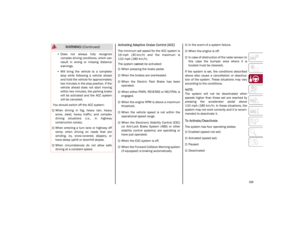 111
111 112
112 113
113 114
114 115
115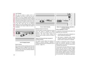 116
116 117
117 118
118 119
119 120
120 121
121 122
122 123
123 124
124 125
125 126
126 127
127 128
128 129
129 130
130 131
131 132
132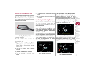 133
133 134
134 135
135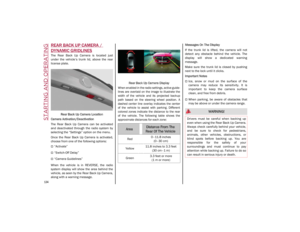 136
136 137
137 138
138 139
139 140
140 141
141 142
142 143
143 144
144 145
145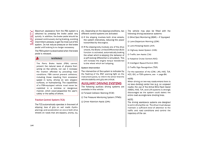 146
146 147
147 148
148 149
149 150
150 151
151 152
152 153
153 154
154 155
155 156
156 157
157 158
158 159
159 160
160 161
161 162
162 163
163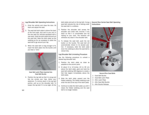 164
164 165
165 166
166 167
167 168
168 169
169 170
170 171
171 172
172 173
173 174
174 175
175 176
176 177
177 178
178 179
179 180
180 181
181 182
182 183
183 184
184 185
185 186
186 187
187 188
188 189
189 190
190 191
191 192
192 193
193 194
194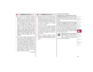 195
195 196
196 197
197 198
198 199
199 200
200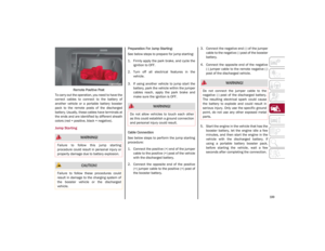 201
201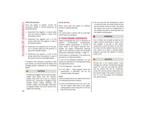 202
202 203
203 204
204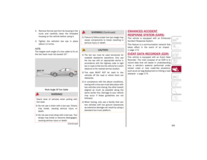 205
205 206
206 207
207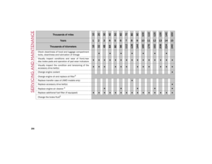 208
208 209
209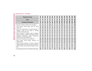 210
210 211
211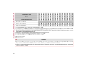 212
212 213
213 214
214 215
215 216
216 217
217 218
218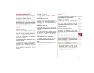 219
219 220
220 221
221 222
222 223
223 224
224 225
225 226
226 227
227 228
228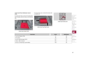 229
229 230
230 231
231 232
232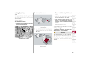 233
233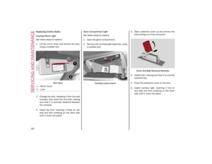 234
234 235
235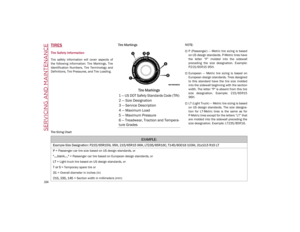 236
236 237
237 238
238 239
239 240
240 241
241 242
242 243
243 244
244 245
245 246
246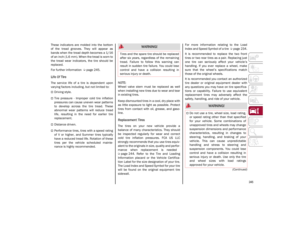 247
247 248
248 249
249 250
250 251
251 252
252 253
253 254
254 255
255 256
256 257
257 258
258 259
259 260
260 261
261 262
262 263
263 264
264 265
265 266
266 267
267 268
268 269
269 270
270 271
271 272
272 273
273 274
274 275
275 276
276 277
277 278
278 279
279 280
280 281
281 282
282 283
283