2021 ALFA ROMEO GIULIA window
[x] Cancel search: windowPage 11 of 284

9
Adaptive Frontlight System
(AFS Function) — If Equipped ................ 44 Turn Signals ........................................... 44
Lane Change Assist ............................... 44
Static Bending Light Function (SBL) —
If Equipped ............................................. 44
INTERIOR LIGHTS .....................................44
Front Map Reading Lights ..................... 45
Interior Ambient Lighting ....................... 45
Rear Overhead Light .............................. 46
Instrument Panel Dimmer Control ....... 46
WINDSHIELD WIPERS AND WASHERS....46
Windshield Wiper Operation ................ 47
Rain Sensing Wipers.............................. 47
CLIMATE CONTROL .................................48
Automatic Dual-Zone Climate
Control System ...................................... 49
INTERIOR STORAGE AND EQUIPMENT....55
Glove Compartment .............................. 55
Center Console ...................................... 56
Power Outlet........................................... 56
Cigar Lighter And Ash Tray —
If Equipped ............................................. 57
Wireless Charging Pad — If Equipped ... 57
POWER WINDOWS ...................................58
Power Window Controls......................... 58
POWER SUNROOF — IF EQUIPPED ..........60
Power Sunroof........................................ 60
Opening And Closing The Sunroof ........ 60
Venting Sunroof ..................................... 61
Sun Shade Operation ............................ 61
Pinch Protect Feature ............................ 61
Re-Initialization Procedure .................... 61
Sunroof Maintenance ............................ 61
HOOD ........................................................ 62
Opening .................................................. 62
Closing.................................................... 62
TRUNK ...................................................... 63
Opening .................................................. 63
Closing.................................................... 64
Trunk Initialization ................................. 64
Trunk Specifications ............................. 64
ENVIRONMENTAL PROTECTION
SYSTEMS .................................................. 65
ACTIVE AERODYNAMIC SPOILER
(QUADRIFOGLIO VEHICLES) .................... 65
Carbon Fiber Active Aero Front
Spoiler .................................................... 65
GETTING TO KNOW YOUR INSTRUMENT
PANEL
INSTRUMENT PANEL FEATURES............. 66
Instrument Cluster ................................ 66
Tachometer............................................ 67
Engine Oil Temperature Gauge ............ 67
Fuel Level Gauge ................................... 68
Speedometer ......................................... 68
INSTRUMENT CLUSTER DISPLAY............ 68
Instrument Cluster Display
Description ............................................. 68 Reconfigurable Instrument Cluster
Display.................................................... 68 Reconfigurable Display Items ............... 68
Customer Programmable Settings ....... 72
WARNING LIGHTS AND MESSAGES
ON THE INSTRUMENT PANEL ................. 73
Red Warning Lights ............................... 73
Amber Warning Lights ........................... 75 Green Indicator Lights ...........................77
Blue Indicator Lights ..............................77
Red Symbols...........................................78
Amber Symbols ......................................79
Green Symbols .......................................83
Blue Symbols .......................................... 83
ONBOARD DIAGNOSTIC SYSTEM ...........84
Onboard Diagnostic System (OBD II)
Cybersecurity .......................................... 84
EMISSIONS INSPECTION AND
MAINTENANCE PROGRAMS ....................85
STARTING AND OPERATING
STARTING THE ENGINE ............................86
Starting Procedure .................................86
Remote Starting System ........................86
Cold Weather Operation ........................87
Extended Park Starting ..........................87
If Engine Fails To Start ...........................88
After Starting — Warming Up The
Engine .....................................................88 Stopping The Engine ..............................88
Turbocharger Cool Down .......................88
ENGINE BLOCK HEATER —
IF EQUIPPED ............................................89
ENGINE BREAK-IN
RECOMMENDATIONS ...............................89
Engine Break-In ......................................89
ELECTRIC PARK BRAKE (EPB) .................90
Electric Park Brake (EPB) Operating
Modes .....................................................92 Safe Hold ................................................92
21_GA_OM_EN_USC_t.book Page 9
Page 21 of 284

19
(Continued)
IGNITION SWITCH
Keyless Push Button Ignition
This feature allows the driver to operate the
ignition switch with the push of a button as
long as the key fob is in the passenger
compartment.
The START/STOP ignition button has several
operating modes. These modes are OFF, ACC,
and ON/RUN.START/STOP Ignition Button
The push button ignition can be placed in the
following modes:
OFF
The engine is stopped
Steering is locked
Some electrical devices (e.g. central
locking, alarm, etc.) are still available ACC
Engine is not started
Some electrical devices are available (e.g.
power windows)
ON/RUN
The engine will start (when foot is on the
brake pedal)
All the electrical devices are available (e.g.
climate controls, etc.)
If the ignition switch does not change the
mode by pushing the button, the key fob may
have a low or depleted battery. In this situa -
tion, a back up method can be used to operate
the ignition switch. Proceed as follows:
1. Lift the front armrest.
2. Lay the key fob on the indicated spot in the bottom of the center console, positioning
the key fob as shown in the following
image, while pushing the START/STOP
ignition button to start the ignition.
Key Fob Placement Location
NOTE:
For more information on proper engine
starting procedures, see
Ú
page 86.
With the keyless ignition in the ACC position,
if 30 minutes pass with the gear selector in
PARK and the engine off, the ignition will
automatically reset to the OFF position.
When opening the driver's door with the
ignition in the ACC position (engine not
running), a chime will sound to remind you
to place the ignition in the OFF position. In
addition to the chime, the message will
display “Ignition Or Accessory On” in the
cluster
Ú
page 273.
WARNING!
When exiting the vehicle, always make
sure the ignition is in the OFF mode,
remove the key fob from the vehicle, and
lock your vehicle.
Never leave children alone in a vehicle, or
with access to an unlocked vehicle.
Allowing children to be in a vehicle unat -
tended is dangerous for a number of
reasons. A child or others could be seri -
ously or fatally injured. Children should be
warned not to touch the parking brake,
brake pedal or the gear selector.
21_GA_OM_EN_USC_t.book Page 19
Page 22 of 284

GETTING TO KNOW YOUR VEHICLE
20
REMOTE START — IF EQUIPPED
This system uses the key fob to start
the engine conveniently from
outside the vehicle while still main-
taining security.
NOTE:
Obstructions between the vehicle and key fob
may reduce this range
Ú
page 273.
How To Use Remote Start
Push the Remote Start button on the key fob
twice within five seconds. The vehicle doors
will lock, the turn signals will flash twice, and
the horn will chirp twice. Pushing the Remote
Start button a third time shuts the engine off.
NOTE:
With Remote Start, the engine will only run
for 15 minutes.
Remote Start can only be used twice.
If an engine fault is present or fuel level is
low, the vehicle will start and then shut
down in 10 seconds.
The park lamps will turn on and remain on
during Remote Start mode.
For security, power window operation is
disabled when the vehicle is in the Remote
Start mode.
The ignition must be placed in the ACC posi -
tion before the Remote Start sequence can
be repeated for a third cycle.
All of the following conditions must be met
before the engine will Remote Start:
Gear selector in PARK
Doors closed
Hood closed
Trunk closed
Hazard switch off
Brake switch inactive (brake pedal not
pushed)
Battery at an acceptable charge level
PANIC button not pushed
System not disabled from previous remote
start event
Vehicle Security system indicator flashing
Ignition in OFF position
Fuel level meets minimum requirement
Vehicle Security system is not signaling an
intrusion
Malfunction Indicator Light is not illuminated
Do not leave the key fob in or near the
vehicle, or in a location accessible to chil -
dren, and do not leave the ignition of a
vehicle equipped with Keyless Enter-N-Go
in the ON/RUN mode. A child could
operate power windows, other controls, or
move the vehicle.
Do not leave children or animals inside
parked vehicles in hot weather. Interior
heat build-up may cause serious injury or
death.
CAUTION!
An unlocked vehicle is an invitation for
thieves. Always remove key fob from the
vehicle and lock all doors when leaving the
vehicle unattended.
WARNING! (Continued) WARNING!
Do not start or run an engine in a closed
garage or confined area. Exhaust gas
contains Carbon Monoxide (CO) which is
odorless and colorless. Carbon Monoxide
is poisonous and can cause serious injury
or death when inhaled.
Keep key fobs away from children. Opera -
tion of the Remote Start system, windows,
door locks or other controls could cause
serious injury or death.
21_GA_OM_EN_USC_t.book Page 20
Page 24 of 284

GETTING TO KNOW YOUR VEHICLE
22
(Continued)
NOTE:
The driver's door key cylinder and trunk
button on the key fob cannot arm or disarm
the Vehicle Security system. Use of the door
key cylinder when the system is armed will
sound the alarm when the door is opened.
When the Vehicle Security system is armed,
the interior power door lock switches will
not unlock the doors.
The Vehicle Security system is designed to
protect your vehicle. However, you can create
conditions where the system will give you a
false alarm. If one of the previously described
arming sequences has occurred, the Vehicle
Security system will arm, regardless of
whether you are in the vehicle or not. If you
remain in the vehicle and open a door, the
alarm will sound. If this occurs, disarm the
Vehicle Security system.
If the Vehicle Security system is armed and the
battery becomes disconnected, the Vehicle
Security system will remain armed when the
battery is reconnected; the exterior lights will
flash, and the horn will sound. If this occurs,
disarm the Vehicle Security system.
NOTE:
The alarm does not disarm when the doors are
unlocked by inserting the blade of the emer -
gency key (found inside the key fob) into the
door handle lock cylinder.
Volumetric/Anti-Lift Protection — If
Equipped
To ensure the correct operation of the Volu -
metric/Anti-Lift Protection system, completely
close the side windows.
To disable the function, push the Volumetric/
Anti-Lift Protection button before activating
the alarm.
When the function is disabled, the light on the
Volumetric/Anti-Lift Protection button flashes
for several seconds.
Volumetric/Anti-Lift Protection Button
Any disabling of the Volumetric/Anti-Lift
Protection must be repeated each time the
instrument panel is switched off.
DOORS
Power Door Locks
The power door lock switches are located on
each front door panel. Push the switch to lock
or unlock the doors.
Door Lock And Unlock Switch Panel
WARNING!
Do not leave children or animals inside
parked vehicles in hot weather. Interior
heat build-up may cause serious injury or
death.
For personal security and safety in the
event of a collision, lock the vehicle doors
as you drive as well as when you park and
leave the vehicle.
21_GA_OM_EN_USC_t.book Page 22
Page 25 of 284

23
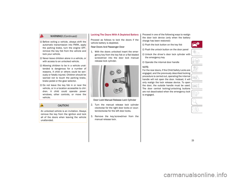
Locking The Doors With A Depleted Battery
Proceed as follows to lock the doors if the
vehicle battery is depleted.
Rear Doors And Passenger Door
1. With the doors unlocked insert the emer-
gency key from the key fob or a flat bladed
screwdriver into the door lock manual
release lock cylinder.
Door Lock Manual Release Lock Cylinder
2. Turn the manual release lock cylinder clockwise for the right door locks or coun -
terclockwise for the left door locks.
3. Remove the key/screwdriver from the manual release lock. Proceed in one of the following ways to realign
the door lock device (only when the battery
charge has been restored):
Push the lock button on the key fob
Push the unlock button on the door panel
Unlock the driver’s door lock cylinder with
the emergency key
Operate the internal door handle
NOTE:
For the rear doors, if the Child Safety Locks are
engaged, and the previously described locking
procedure is carried out, operating the internal
handle will not open the door. Instead, it will
only realign the lock release device. To open
the door, the outside handle must be used.
The door central locking/unlocking buttons
are not deactivated when the emergency lock
is engaged.
Before exiting a vehicle, always shift the
automatic transmission into PARK, apply
the parking brake, turn the engine OFF,
remove the key fob from the vehicle and
lock your vehicle.
Never leave children alone in a vehicle, or
with access to an unlocked vehicle.
Allowing children to be in a vehicle unat -
tended is dangerous for a number of
reasons. A child or others could be seri -
ously or fatally injured. Children should be
warned not to touch the parking brake,
brake pedal or the gear selector.
Do not leave the key fob in or near the
vehicle, or in a location accessible to chil -
dren. A child could operate power
windows, other controls, or move the
vehicle.
CAUTION!
An unlocked vehicle is an invitation. Always
remove the key from the ignition and lock
all of the doors when leaving the vehicle
unattended.
WARNING! (Continued)
21_GA_OM_EN_USC_t.book Page 23
Page 28 of 284

GETTING TO KNOW YOUR VEHICLE
26
Automatic Door Locks — If Equipped
The auto door lock feature default condition is
enabled. When enabled, the door locks will
lock automatically when the vehicle's speed
exceeds 12 mph (20 km/h). The auto door
lock feature is enabled/disabled through the
radio screen. Refer to the Information and
Entertainment System Owner’s Manual
Supplement for further information.
Child-Protection Door Lock System — Rear
Doors
To provide a safer environment for small chil-
dren riding in the rear seats, the rear doors are
equipped with a Child-Protection Door Lock
system.
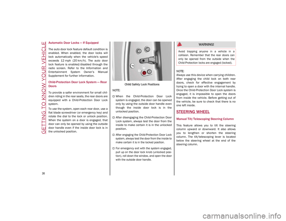
To use the system, open each rear door, use a
flat blade screwdriver (or emergency key) and
rotate the dial to the lock or unlock position.
When the system on a door is engaged, that
door can only be opened by using the outside
door handle even if the inside door lock is in
the unlocked position. Child Safety Lock Positions
NOTE:
When the Child-Protection Door Lock
system is engaged, the door can be opened
only by using the outside door handle even
though the inside door lock is in the
unlocked position.
After disengaging the Child-Protection Door
Lock system, always test the door from the
inside to make certain it is in the unlocked
position.
After engaging the Child-Protection Door Lock
system, always test the door from the inside to
make certain it is in the locked position.
For emergency exit with the system engaged,
pull up on the door lock knob (unlocked posi -
tion), roll down the window, and open the door
with the outside door handle.
NOTE:
Always use this device when carrying children.
After engaging the child lock on both rear
doors, check for effective engagement by
trying to open a door with the internal handle.
Once the Child-Protection Door Lock system is
engaged, it is impossible to open the doors
from inside the vehicle. Before getting out of
the vehicle, be sure to check that there is no
one left inside.
STEERING WHEEL
Manual Tilt/Telescoping Steering Column
This feature allows you to tilt the steering
column upward or downward. It also allows
you to lengthen or shorten the steering
column. The tilt/telescoping lever is located
below the steering wheel at the end of the
steering column.
WARNING!
Avoid trapping anyone in a vehicle in a
collision. Remember that the rear doors can
only be opened from the outside when the
Child-Protection locks are engaged (locked).
21_GA_OM_EN_USC_t.book Page 26
Page 38 of 284

GETTING TO KNOW YOUR VEHICLE
36
For upward adjustment, pull up on the head
restraint until it clicks into place.
For downward adjustment, push in the adjust-
ment button and lower the head restraint
while holding the button to the desired height.
Rear Head Restraint
NOTE:
To allow maximum visibility for the driver, if the
head restraints are not in use, lower the head
restraint all the way.
Head Restraint Removal
To remove adjustable head restraints,
proceed as follows:
1. Raise the head restraints to their maximum height. 2. Push the adjustment button and the
release button at the side of the two
supports.
3. Remove the head restraints by pulling them upwards.
To reinstall the head restraints, proceed as
follows:
1. Hold down both the adjustment button and release button while placing the head
restraint post into the holes.
2. Then, reposition the head restraint to the appropriate height for the passengers.
MIRRORS
Automatic Dimming Mirror
The rearview mirror can be adjusted up, down,
left, and right. The mirror should be adjusted
to center on the view through the rear window.
This mirror automatically adjusts for headlight
glare from vehicles behind you.
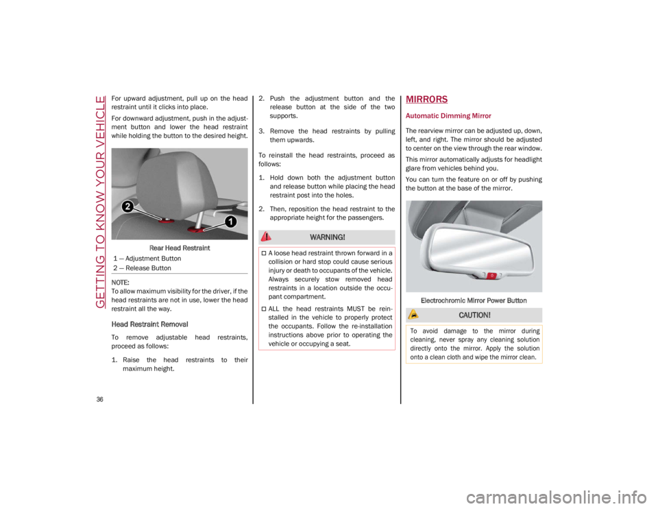
You can turn the feature on or off by pushing
the button at the base of the mirror.
Electrochromic Mirror Power Button
1 — Adjustment Button
2 — Release Button
WARNING!
A loose head restraint thrown forward in a
collision or hard stop could cause serious
injury or death to occupants of the vehicle.
Always securely stow removed head
restraints in a location outside the occu
-
pant compartment.
ALL the head restraints MUST be rein -
stalled in the vehicle to properly protect
the occupants. Follow the re-installation
instructions above prior to operating the
vehicle or occupying a seat. CAUTION!
To avoid damage to the mirror during
cleaning, never spray any cleaning solution
directly onto the mirror. Apply the solution
onto a clean cloth and wipe the mirror clean.
21_GA_OM_EN_USC_t.book Page 36
Page 39 of 284

37
Vanity Mirror
On the driver and passenger sun visor, there is
a light which illuminates the sun visor mirror
when folded down.Sun Visor Mirror
The courtesy light turns on automatically by
lifting the cover.
Sun Visors
The sun visors are located at the sides of the
interior rearview mirror. They can be adjusted
forward and toward the side window.
To direct the visor toward the side window,
detach the visor from the interior rearview
mirror side hook and turn it towards the side
window. From this position, the sun visor can also be
extended toward the rear of the vehicle for
additional blockage of sunlight.
There are courtesy mirrors with lights on the
back of the sun visors.
Rotate Sun Visor Toward Passenger Window
NOTE:
A rear facing child restraint system should
never be fitted in the front passenger seat.
Always comply with the instructions on the sun
visor
Ú
page 174.Outside Power Mirrors
The power mirror switch is located on the
driver’s side door trim panel.
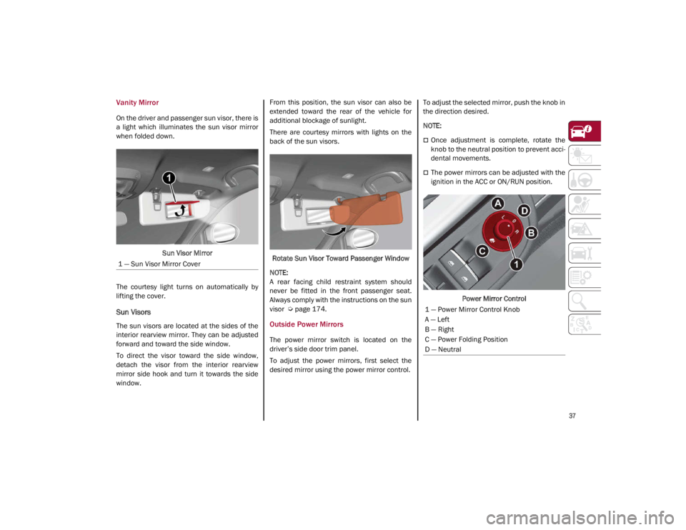
To adjust the power mirrors, first select the
desired mirror using the power mirror control. To adjust the selected mirror, push the knob in
the direction desired.
NOTE:
Once adjustment is complete, rotate the
knob to the neutral position to prevent acci
-
dental movements.
The power mirrors can be adjusted with the
ignition in the ACC or ON/RUN position.
Power Mirror Control
1 — Sun Visor Mirror Cover
1 — Power Mirror Control Knob
A — Left
B — Right
C — Power Folding Position
D — Neutral
21_GA_OM_EN_USC_t.book Page 37