Page 105 of 126

Periodic maintenance an d a djustment
8-31
8
battery tends to discharge more quick-
ly if the vehicle is equipped with op-
tional electrical accessories.
NOTICE
ECA16522
To char
ge a VRLA (Valve Re gulate d
Lea d Aci d) battery, a special (con-
stant-volta ge) battery char ger is re-
quire d. Usin g a conventional b attery
char ger will damag e the battery.To store the battery
1. If the vehicle will not be used for more than one month, remove the
battery, fully charge it, and then
place it in a cool, dry place.
NOTICE: When removin g the
b attery, be sure turn the vehicle
power off, then d isconnect the
ne gative lead before discon-
nectin g the positive lea d.
[ECA21900]
2. If the battery will be stored for
more than two months, check it at
least once a month and fully
charge it if necessary. 3. Fully charge the battery before in-
stallation. NOTICE: When install-
in g the battery, connect the
positive lea d b efore connectin g
the ne gative lea d.
[ECA21910]
4. After installation, make sure that
the battery leads are properly con-
nected to the battery terminals.NOTICE
ECA16531
Always keep the b attery charged .
Storin g a dischar ged battery can
cause permanent b attery damag e.
EAU81472
Replacin g the fusesFuse box1, brake light fuse and cruise
control fuse are located behind panel
A. (See page 8-9.)
Fuse box 2 and main fuse are located
behind the windshield.1. Fuse box 1
2. ABS control unit fuse
3. Auxiliary DC jack fuse
4. Headlight fuse
5. Electronic throttle valve fuse
6. ABS motor fuse
7. ABS solenoid fuse
8. Spare fuse
9. Cruise control fuse (XP560D)
10.Brake light fuse (XP560D)2
3
4
5
6
7
8
8
9
10
1 1
UB3TE0E0.book Page 31 Tuesday, September 17, 2019 9:35 AM
Page 106 of 126
Periodic maintenance an d a djustment
8-32
8
TIPTo access the main fuse, remove the
starter relay cover.To access fuse box 2 and the main
fuse, proceed as follows. 1. Remove the screw access covers
by removing the quick fasteners.
2. Remove the caps.
3. Remove the windshield by remov- ing the screws. 4. Remove the inner panel by remov-
ing the bolts and quick fasteners.
5. Install the inner panel by installing the bolts and quick fasteners.1. Starter relay cover
2. Main fuse
3. Spare main fuse
4. Fuse box 2
5. Signaling system fuse
6. Ignition fuse
7. Taillight fuse
8. Radiator fan motor fuse
9. Fuel injection system fuse
10.Backup fuse
11.Spare fuse
12.Spare fuse (XP560D)
13.Windshield motor fuse (XP560D)
14.Baggage fuse (XP560E)
5
6
7
8
9
10
12 13,14 11
1 1
2
3
2
3
4
4
1. Screw access cover
2. Quick fastener
1. Cap
1
212
1
1. Windshield
2. Screw
1. Inner panel
2. Bolt
3. Quick fastener
12
2 21 2
2
3 3
2
UB3TE0E0.book Page 32 Tuesday, September 17, 2019 9:35 AM
Page 107 of 126

Periodic maintenance an d a djustment
8-33
8
6. Install the windshield by installing
the screws.
7. Install the caps.
8. Install the screw access covers by installing the quick fasteners.
If a fuse is blown, replace it as follows. 1. Turn the vehicle power off.
2. Remove the blown fuse, and then install a new fuse of the specified
amperage. WARNING! Do not
use a fuse of a hi gher ampera ge
ratin g than recommen ded to
avoi d causin g extensive dam-
a g e to the electrical system an d
possi bly a fire.
[EWA15132]
3. Turn the vehicle power on and turn
on the electrical circuit in question
to check if the device operates.
4. If the fuse immediately blows again, have a Yamaha dealer
check the electrical system.
1. Screw access cover
1
Specified fuses:
Main fuse:
40.0 A
Headlight fuse: 7.5 A
Taillight fuse: 7.5 A
Signaling system fuse:
7.5 A
Ignition fuse: 7.5 A
Radiator fan motor fuse: 15.0 A
Fuel injection system fuse:
7.5 A
ABS control unit fuse: 7.5 A
ABS motor fuse: 30.0 A
ABS solenoid fuse:
15.0 A
Auxiliary DC jack fuse: 2.0 A
Backup fuse: 15.0 A
Electronic throttle valve fuse:
7.5 A
Baggage fuse: 7.5 A (XP560E)
Brake light fuse: 1.0 A (XP560D)
Cruise control fuse:
1.0 A (XP560D)
Windshield motor fuse: 20.0 A (XP560D)
UB3TE0E0.book Page 33 Tuesday, September 17, 2019 9:35 AM
Page 108 of 126

Periodic maintenance an d a djustment
8-34
8
EAU80380
Vehicle li ghtsExcept for the license plate light bulb,
this model’s lights are all LED.
If an LED light does not come on,
check the fuses and then have a
Yamaha dealer check the vehicle. If the license plate light does not come on,
check and replace the bulb. (See page
8-34.)NOTICE
ECA16581
Do not affix any type of tinted film or
stickers to the head light lens.
EAU81491
Replacin g the license plate
li g ht bul b1. Remove the nuts securing the li-
cense plate light unit.
2. Pull the license plate light unit sep- arate from the rear fender. (Rein-
stall the collars if they fall out.) 3. Remove the burnt-out bulb by
pulling it out.
4. Insert a new bulb into the socket, and push the socket in place.
5. Install the license plate unit onto the rear fender.
6. Install the nuts and tighten to the specified torque.
1. Headlight
2. Auxiliary light2 1
2
1
1. License plate light unit
2. Nut
21
1. Collar
2. License plate light bulb
3. License plate light unitTi
ghtenin g torque:
License plate light unit nut:
3.8 N·m (0.38 kgf·m, 2.8 lb·ft)
3
2
1
UB3TE0E0.book Page 34 Tuesday, September 17, 2019 9:35 AM
Page 109 of 126

Periodic maintenance an d a djustment
8-35
8
EAU25865
Trou bleshootin gAlthough your Yamaha received a thor-
ough inspection before shipment from
the factory, trouble may occur during
operation. Any problem in the fuel,
compression, or ignition systems, for
example, can cause poor starting and
loss of power.
The following troubleshooting chart
represents a quick and easy procedure
for checking these vital systems your-
self. However, should your vehicle re-
quire any repair, take it to an
authorized Yamaha dealer whose
skilled technicians have the necessary
tools, experience, and know-how to
properly service your Yamaha vehicle.
Be sure to use only genuine Yamaha
replacement parts. Although imitation
parts may look similar to genuine parts,
they are often inferior in quality, have a
shorter service life, and can lead to an
expensive repair bill later on.
WARNING
EWA15142
When checkin g the fuel system, d o
not smoke, an d make sure there are
no open flames or sparks in the ar- ea, inclu
din g pilot li ghts from water
heaters or furnaces. Gasoline or
g asoline vapors can i gnite or ex-
plo de, causin g severe injury or prop-
erty damag e.
EAU77992
Smart key system trou bleshootin g
Please check the following items when
the smart key system does not work. Is the smart key turned on? (See
page 3-5.)
Is the smart key battery dis-
charged? (See page 3-6.)
Is the smart key battery installed
correctly? (See page 3-6.)
Is the smart key being used in a lo-
cation with strong radio waves or
other electromagnetic noise? (See
page 3-1.)
Are you using the smart key that is
registered to the vehicle?
Is the vehicle battery discharged?
When the vehicle battery is dis-
charged, the smart key system will
not operate. Please have the vehi-
cle battery charged or replaced.
(See page 8-30.) If the smart key system does not work
after checking the above items, have a
Yamaha dealer check the smart key
system.
TIPSee Emergency mode on page 8-38
for information on starting the engine
without the smart key.
UB3TE0E0.book Page 35 Tuesday, September 17, 2019 9:35 AM
Page 110 of 126

Periodic maintenance an d a djustment
8-36
8
EAU86350
Trou bleshootin g chart
Check the fuel level in
the fuel tank.1. Fuel
There is enough fuel.
There is no fuel.
Check the battery.
Supply fuel.
The engine does not start.
Check the battery.
Try starting the engine.4. Compression
There is compression.
There is no compression.
The engine does not start.
Have a Yamaha dealer check the vehicle.Have a Yamaha dealer check the vehicle.
Remove the spark plug
and check the electrodes.3. Ignition
Wipe off with a dry cloth and correct the
spark plug gap, or replace the spark plug(s). Have a Yamaha dealer check the vehicle.
The engine does not start.
Check the compression.
Operate the electric starter.2. Battery
The engine turns over
quickly.
The engine turns over
slowly.
The battery is good.
DryWet
Try starting the engine.
Check the battery lead connections,
and charge the battery if necessary.
The engine does not start.
Check the ignition.
UB3TE0E0.book Page 36 Tuesday, September 17, 2019 9:35 AM
Page 111 of 126

Periodic maintenance an d a djustment
8-37
8
EAU86420
En gine overheatin g
WARNING
EWAT1041
Do not remove the ra diator cap when the en gine an d ra diator are hot. Scal din g hot flui d an d steam may be
b lown out un der pressure, which coul d cause serious injury. Be sure to wait until the en gine has coole d.
Place a thick ra g, like a towel, over the ra diator cap, an d then slowly rotate the cap counterclockwise to the
d etent to allow any resi dual pressure to escape. When the hissin g soun d has stoppe d, press down on the cap
while turnin g it counterclockwise, an d then remove the cap.TIPIf coolant is not available, tap water can be temporarily used instead, provided that it is changed to the recommended cool-
ant as soon as possible.
Wait until the
engine has cooled.
Check the coolant level in the
reservoir and radiator.
The coolant level
is OK.The coolant level is low.
Check the cooling system
for leakage.
Have a Yamaha dealer checkand repair the cooling system.Add coolant. (See TIP.)
Start the engine. If the engine overheats again,
have a
Yamaha dealer check
and repair the cooling system.
There is
leakage.
There is
no leakage.
UB3TE0E0.book Page 37 Tuesday, September 17, 2019 9:35 AM
Page 112 of 126

Periodic maintenance an d a djustment
8-38
8
EAU77373
Emer gency mo deWhen the smart key is lost, damaged,
or its battery has discharged, the vehi-
cle can still be turned on and the en-
gine started. You will need a
mechanical key and the smart key sys-
tem identification number. To operate
the vehicle in emergency mode, carry
out the following steps.TIPEmergency mode operation will be
cancelled if the respective steps are
not carried out within the time set for
each operation or if the “OFF/LOCK”
switch is pushed.1. Stop the vehicle in a safe place.
2. Unlock the seat by inserting the
mechanical key into the lock lo-
cated right side of body and turn it
counter clockwise. 3. Open the seat and check that the
trunk light comes on.
4. Push the “ON/ ” switch once.
5. Without completely shutting the seat, raise and lower it three times
within 10 seconds.
TIPUse the rear storage compartment
light as a guide when raising and low-
ering the seat.
The smart key system indicator
light on the speedometer will
come on for three seconds to indi-
cate the transition to emergency
mode. 6. After the smart key system indica-
tor light goes off, use the “ / ”
switch to enter the identification
number.
1. Smart key system indicator light “ ”
1. Identification number
1 1
123456
1
UB3TE0E0.book Page 38 Tuesday, September 17, 2019 9:35 AM
 1
1 2
2 3
3 4
4 5
5 6
6 7
7 8
8 9
9 10
10 11
11 12
12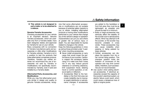 13
13 14
14 15
15 16
16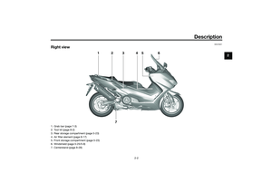 17
17 18
18 19
19 20
20 21
21 22
22 23
23 24
24 25
25 26
26 27
27 28
28 29
29 30
30 31
31 32
32 33
33 34
34 35
35 36
36 37
37 38
38 39
39 40
40 41
41 42
42 43
43 44
44 45
45 46
46 47
47 48
48 49
49 50
50 51
51 52
52 53
53 54
54 55
55 56
56 57
57 58
58 59
59 60
60 61
61 62
62 63
63 64
64 65
65 66
66 67
67 68
68 69
69 70
70 71
71 72
72 73
73 74
74 75
75 76
76 77
77 78
78 79
79 80
80 81
81 82
82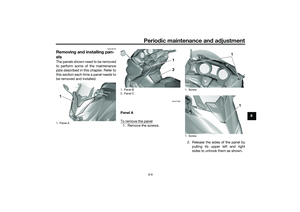 83
83 84
84 85
85 86
86 87
87 88
88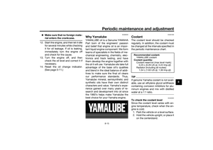 89
89 90
90 91
91 92
92 93
93 94
94 95
95 96
96 97
97 98
98 99
99 100
100 101
101 102
102 103
103 104
104 105
105 106
106 107
107 108
108 109
109 110
110 111
111 112
112 113
113 114
114 115
115 116
116 117
117 118
118 119
119 120
120 121
121 122
122 123
123 124
124 125
125