Page 57 of 126

Instrument and control functions
5-21
5
EAU13222
FuelMake sure there is sufficient gasoline in
the tank.
WARNING
EWA10882
Gasoline an d gasoline vapors are
extremely flammab le. To avoid fires
an d explosions an d to re duce the
risk of injury when refuelin g, follow
these instructions.1. Before refueling, turn off the en- gine and be sure that no one is sit-
ting on the vehicle. Never refuel
while smoking, or while in the vi-
cinity of sparks, open flames, or
other sources of ignition such as
the pilot lights of water heaters
and clothes dryers.
2. Do not overfill the fuel tank. When refueling, be sure to insert the
pump nozzle into the fuel tank filler
hole. Stop filling when the fuel
reaches the bottom of the filler
tube. Because fuel expands when
it heats up, heat from the engine or
the sun can cause fuel to spill out
of the fuel tank. 3. Wipe up any spilled fuel immedi-
ately. NOTICE: Immediately
wipe off spille d fuel with a clean,
d ry, soft cloth, since fuel may
d eteriorate painte d surfaces or
plastic parts.
[ECA10072]
4. Be sure to securely close the fuel tank cap.
WARNING
EWA15152
Gasoline is poisonous an d can
cause injury or d eath. Handle gaso-
line with care. Never siphon gasoline
b y mouth. If you shoul d swallow
some gasoline or inhale a lot of gas-
oline vapor, or g et some gasoline in
your eyes, see your doctor imme di- ately. If g
asoline spills on your skin,
wash with soap an d water. If gaso-
line spills on your clothin g, chan ge
your clothes.
EAU86072
Your Yamaha engine was designed to
use unleaded gasoline with a research
octane number of 95 or higher. If en-
gine knocking or pinging occurs, use a
gasoline of a different brand or higher
octane rating.
1. Maximum fuel level
2. Fuel tank filler tube
1 2
Recommen
ded fuel:
Unleaded gasoline (E10 acceptable)
Octane num ber (RON):
95
Fuel tank capacity: 15 L (4.0 US gal, 3.3 Imp.gal)
Fuel tank reserve:
3.0 L (0.79 US gal, 0.66 Imp.gal)
UB3TE0E0.book Page 21 Tuesday, September 17, 2019 9:35 AM
Page 58 of 126
.
Confirm the gasoline pump nozzle
has the sa")
Instrument and control functions
5-22
5
TIP This mark identifies the recom-
mended fuel for this vehicle as
specified by European regulation
(EN228).
Confirm the gasoline pump nozzle
has the same fuel identification
mark.Gasohol
There are two types of gasohol: gaso-
hol containing ethanol and that con-
taining methanol. Gasohol containing
ethanol can be used if the ethanol con-
tent does not exceed 10% (E10). Gas-
ohol containing methanol is not
recommended by Yamaha because it
can cause damage to the fuel system
or vehicle performance problems.
NOTICE
ECA11401
Use only unlea ded g asoline. The use
of lea ded g asoline will cause severe
d amag e to internal en gine parts,
such as the valves an d piston rin gs,
as well as to the exhaust system.
EAU80200
Fuel tank overflow hoseBefore operating the vehicle: Check the fuel tank overflow hose
connection.
Check the fuel tank overflow hose
for cracks or damage, and replace
it if necessary.
Make sure that the end of the fuel
tank overflow hose is not blocked,
and clean it if necessary.
Make sure that the end of the fuel
tank overflow hose is positioned
as shown.TIPSee page 8-12 for canister information.
E5
E10
1. Fuel tank overflow hose
1
UB3TE0E0.book Page 22 Tuesday, September 17, 2019 9:35 AM
Page 59 of 126
 to reduce harmful exhaust
emissions.
WARNING
EWA10863
The exhaust system is hot a")
Instrument and control functions
5-23
5
EAU13435
Catalytic converterThe exhaust system contains catalytic
converter(s) to reduce harmful exhaust
emissions.
WARNING
EWA10863
The exhaust system is hot after op-
eration. To prevent a fire hazar d or
b urns:
Do not park the vehicle near
possi ble fire hazar ds such as
g rass or other materials that
easily burn.
Park the vehicle in a place
where pe destrians or chil dren
are not likely to touch the hot
exhaust system.
Make sure that the exhaust sys-
tem has coole d down before
d oin g any maintenance work.
Do not allow the en gine to i dle
more than a few minutes. Lon g
i d lin g can cause a buil d-up of
heat.
EAU88751
Stora ge compartmentsFront storag e compartment
To open the storage compartment,
press the button.
Open the lid as shown. To close the storage compartment,
push the lid into the original position.
TIPFor XP560D: this compartment has an
electronic lock. (See page 3-12.)Rear storag
e compartment
This storage compartment was de-
signed to hold one full-faced helmet or
two 3/4-faced helmets. NOTICE: The
sha ded area is not a stora ge com-
partment. To prevent damag ing the
seat hin ges, do not place any items
in this area.
[ECA16092]
1. Button
1. Lid
1
1
1. Lid1
UB3TE0E0.book Page 23 Tuesday, September 17, 2019 9:35 AM
Page 60 of 126

Instrument and control functions
5-24
5
TIP Some helmets cannot be stored in
the rear storage compartment be-
cause of their size or shape.
Do not leave the vehicle unattend-
ed with the seat open.
Do not place the smart key inside
a storage compartment. It may get
locked inside and the smart key
system not operate normally.NOTICE
ECA15964
Do not leave the seat open for
an exten ded period of time, oth-
erwise the li ght may cause the
b attery to d ischarge.
Since the storag e compartment
may get wet when washin g the
vehicle, wrap any articles store d
in the compartment in a plastic
b ag .
To avoi d humi dity from sprea d-
in g throu gh the stora ge com-
partment an d to discoura ge
possi ble mold g rowth, wrap wet
articles in a plastic bag b efore
storin g them in the compart-
ment.
Do not keep anythin g valua ble
or breakab le in the stora ge
compartment.
Since the storag e compartment
accumulates heat from the en-
g ine an d from d irect sunli ght, do
not store anythin g su
sceptible
to heat, such as foo d or flamma-
b le items, insi de the compart-
ment.WARNING
EWA20960
Do not exceed the load limit of
1.0 k g (2 l b) for the front storag e
compartment.
Do not exceed the load limit of
5.0 k g (11 l b) for the rear stora ge
compartment.
Do not exceed the maximum
loa d of 195 k g (430 l b) (XP560D)
197 k g (434 l b) (XP560E) for the
vehicle.
1. Rear storage compartment
2. Shaded area
12
UB3TE0E0.book Page 24 Tuesday, September 17, 2019 9:35 AM
Page 61 of 126
Instrument and control functions
5-25
5
EAU81442
Win dshiel d (XP560E)The windshield height can be changed
to one of two positions.
To a djust the win dshiel d hei ght
1. Remove the screw access covers by removing the quick fasteners.
TIPTo remove the quick fastener, rotate its
screwed portion counterclockwise
with a hexagon wrench.2. Remove the caps. 3. Remove the windshield by remov-
ing the screws.
4. Install the windshield to the de- sired position by installing the
screws.
1. Windshield
1
1. Quick fastener
2. Screw access cover1 2
1
1. Cap
1. Screw
1
1 1
UB3TE0E0.book Page 25 Tuesday, September 17, 2019 9:35 AM
Page 62 of 126

Instrument and control functions
5-26
5
5. Tighten the screws to the speci-fied torque. WARNING! A loose
win dshield could cause an acci-
d ent. Be sure to ti ghten the
screws to the specified torque.
[EWA15511]
6. Install the caps.
7. Place the screw access covers,
and then install the quick fasten-
ers.
TIPTo install the quick fastener, set it with
its screwed portion pulled out from the
surface of the quick fastener, and then
push it down to the surface.
EAU39672
Rear view mirrorsThe rear view mirrors of this vehicle
can be folded forward or backward for
parking in narrow spaces. Fold the mir-
rors back to their original position be-
fore riding.
WARNING
EWA14372
Be sure to fol d the rear view mirrors
b ack to their ori ginal position before
ri din g.
1. ScrewTi ghtenin g torque:
Windshield screw: 10 N·m (1.0 kgf·m, 7.4 lb·ft)1 1
1. Screw access cover
1. Quick fastener (before installation)
2. Quick fastener (after installation)
1
12
1. Riding position
2. Parking position
1
1 2
2
2
UB3TE0E0.book Page 26 Tuesday, September 17, 2019 9:35 AM
Page 63 of 126

Instrument and control functions
5-27
5
EAU77584
Shock ab sorber assem bly
WARNING
EWA10222
This shock a bsor ber assem bly con-
tains hig hly pressurize d nitro gen
g as. Rea d an d un derstan d the fol-
lowin g information before han dlin g
the shock ab sorber assem bly.
Do not tamper with or attempt
to open the cylin der assem bly.
Do not su bject the shock a b-
sor ber assem bly to an open
flame or other hi gh heat source.
This may cause the unit to ex-
plod e due to excessive gas
pressure.
Do not d eform or damag e the
cylin der in any way. Cylin der
d amag e will result in poor
d ampin g performance.
Do not d ispose of a damag ed or
worn-out shock a bsor ber
as-
sem bly yourself. Take the shock
a b sor ber assem bly to a Yamaha
d ealer for any service.
For XP560D:
This model is equipped with adjustable
suspension. The spring preload and re-
bound damping force can be adjusted.
Sprin g preloa d
Turn the adjusting ring in direction (a)
to increase the spring preload.
Turn the adjusting ring in direction (b)
to decrease the spring preload.
Align the appropriate notch in the
adjusting ring with the position in-
dicator on the shock absorber.
Use the special wrench included
in the tool kit to make the adjust-
ment. Re
boun d d ampin g force
Turn the adjusting screw in direction (a)
to increase the rebound damping
force.
Turn the adjusting screw in direction (b)
to decrease the rebound damping
force.
To set the rebound damping force, turn
the adjuster in direction (a) until it
stops, and then count the turns in di-
rection (b).1. Spring preload adjusting ring
2. Special wrench
3. Position indicator
1 234
5 67
1(a)
(b)
32
Sprin g preloa d settin g:
Minimum (soft):
7 (XP560D)
Standard:
4 (XP560D)
Maximum (hard): 1 (XP560D)
UB3TE0E0.book Page 27 Tuesday, September 17, 2019 9:35 AM
Page 64 of 126
, it may turn be-
yond the stated specifications,
however such adjustments are ineffec-
tive and ma")
Instrument and control functions
5-28
5
TIPWhen turning the damping force ad-
juster in direction (b), it may turn be-
yond the stated specifications,
however such adjustments are ineffec-
tive and may damage the suspension.
NOTICE
ECA10102
To avoi d d amag ing the mechanism,
d o not attempt to turn b eyond the
maximum or minimum settin gs.
EAU77352
Auxiliary DC jackThis model is equipped with a 12 V
auxiliary DC jack. The DC jack is locat-
ed inside the front storage compart-
ment.NOTICE
ECA15432
The accessory connecte d to the
auxiliary DC jack shoul d not b e used
with the en gine turne d off, an d the
loa d must never excee d 24 W (2 A),
otherwise the fuse may blow or the
b attery may d ischarge.To use the auxiliary DC jack
1. Open the front storage compart- ment.
1. Rebound damping force adjusting screwReboun d d ampin g setting :
Minimum (soft): 3 (XP560D) turn(s) in direction (b)
Standard: 1.25 (XP560D) turn(s) in direction
(b)
Maximum (hard): 0 (XP560D) turn(s) in direction (b)
(a)
(b)
1
1. Auxiliary DC jack
1
UB3TE0E0.book Page 28 Tuesday, September 17, 2019 9:35 AM
 1
1 2
2 3
3 4
4 5
5 6
6 7
7 8
8 9
9 10
10 11
11 12
12 13
13 14
14 15
15 16
16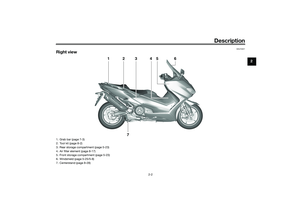 17
17 18
18 19
19 20
20 21
21 22
22 23
23 24
24 25
25 26
26 27
27 28
28 29
29 30
30 31
31 32
32 33
33 34
34 35
35 36
36 37
37 38
38 39
39 40
40 41
41 42
42 43
43 44
44 45
45 46
46 47
47 48
48 49
49 50
50 51
51 52
52 53
53 54
54 55
55 56
56 57
57 58
58 59
59 60
60 61
61 62
62 63
63 64
64 65
65 66
66 67
67 68
68 69
69 70
70 71
71 72
72 73
73 74
74 75
75 76
76 77
77 78
78 79
79 80
80 81
81 82
82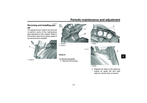 83
83 84
84 85
85 86
86 87
87 88
88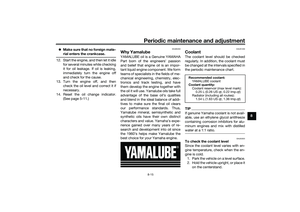 89
89 90
90 91
91 92
92 93
93 94
94 95
95 96
96 97
97 98
98 99
99 100
100 101
101 102
102 103
103 104
104 105
105 106
106 107
107 108
108 109
109 110
110 111
111 112
112 113
113 114
114 115
115 116
116 117
117 118
118 119
119 120
120 121
121 122
122 123
123 124
124 125
125The windshield height can be changed
to one of two positions.
To a djust the win dshiel d hei ght
1. Remove the screw access cover")