Page 25 of 102

Instrument and control functions
3-10
3 short press on the top button will incre-
ment the unit from “9” to “0”. Push the
bottom set button to select the next
digit and set it following the same pro-
cedure as the first digit. Push the bot-
tom set button to select the last digit
and follow the same procedure. Push
the bottom set button to confirm the
value.
TIPThe maximum possible entering
value is 900 km or 600 mi.
The countdown tripmeter will start
as soon as you begin riding. When
the countdown reaches “0” the
display changes to the countdown
tripmeter “TRIP CD” and flashes
10 times.
To reset the countdown tripmeter,
select it and while the digits flash,
push the bottom set button until it
is reset.
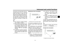
Instantaneous fuel consumption
This function calculates the fuel con-
sumption under current riding condi-
tions.
The instantaneous fuel consumption
display can be set to either “km/L”,
“L/100 km” when using kilometers.
To switch the the fuel consumption
units, push the top set button until the
measurement units change. When us-
ing miles, the fuel consumption unit is
“MPG”.
“km/L”: The distance that can be
traveled on 1.0 L of fuel under the
current riding conditions is shown.“L/100 km”: The amount of fuel
necessary to travel 100 km under
the current riding conditions is
shown.
“MPG”: The distance that can be
traveled on 1.0 Imp.gal of fuel un-
der the current riding conditions is
shown.
To switch the instantaneous fuel con-
sumption settings, push and hold the
left set button until the display chang-
es.
TIPIf traveling at speeds under 20 km/h
Average fuel consumption
1. Instantaneous fuel consumption display
1
1. Average fuel consumption display
1
UBW3E0E0.book Page 10 Friday, May 24, 2019 11:01 AM
Page 26 of 102

Instrument and control functions
3-11
3This display shows the average fuel
consumption since it was last reset.
The average fuel consumption can be
set to either “AVE_ _._ km/L”, “AVE_
_._ L/100 km” when using kilometers.
To switch the fuel consumption units,
push the top set button until the mea-
surement units change. When using
miles, the fuel consumption is “AVE_
_._ MPG”.
“AVE_ _._ km/L”: The average dis-
tance that can be traveled on 1.0 L
of fuel is shown.
“AVE_ _._ L/100 km”: The average
amount of fuel necessary to travel
100 km is shown.
“AVE_ _._ MPG”: The average dis-
tance that can be traveled on
1.0 Imp.gal of fuel is shown.
To reset the average fuel consumption,
select it and while the digits flash push
the bottom set button until it is reset.
TIPAfter resetting the average fuel con-
the vehicle has traveled 1 km (0.6 mi).
Coolant temperature
This display shows the coolant tem-
perature from 40 °C to 116 °C in 1 °C
increments.
If the message “Hi” flashes, stop the
vehicle, then stop the engine, and let it
cool. (See page 6-37.)TIPWhen the coolant temperature is
below 40 °C, “Lo” will be dis-
played.
The coolant temperature varies
with changes in the weather and
engine load.
Air temperature
This display shows the air temperature
from –9 °C to 99 °C in 1 °C increments.TIPWhen the temperature is below –9
°C, “Lo” will be displayed.
The temperature displayed may
vary from the ambient tempera-
ture.
1. Coolant temperature display
1
1. Air temperature display
1
UBW3E0E0.book Page 11 Friday, May 24, 2019 11:01 AM
Page 27 of 102
Instrument and control functions
3-12
3 Brightness control mode
The brightness level of the multi-func-
tion meter unit panel can be adjusted.
To adjust the brightness
1. Turn the key to “OFF”.
2. Push and hold the top set button.
3. Turn the key to “ON” and continue
pushing the top set button until
the display switches to the bright-
ness control mode.
4. Push the bottom set button to set
the brightness level.
5. Push the top set button to confirm
the selected brightness level and
exit the brightness control mode.
TIPThere are 6 brightness level settings.
EAU1234M
Handlebar switchesLeft
1. Brightness level display
1
1. Hazard switch Ž
2.
3. Dimmer switch / Ž
4. Turn signal switch / Ž
5. Horn switch Ž
34512
UBW3E0E0.book Page 12 Friday, May 24, 2019 11:01 AM
Page 28 of 102

Instrument and control functions
3-13
3Right
EAU12362
Pass switch “PASS”
Press this switch to flash the headlight.TIPWhen the dimmer switch is set
to Ž, the passing switch has no ef-
fect.
EAUM4180
Dimmer switch “ / ”
Set this switch to “ ” for the high
beam and to “ ” for the low beam.TIPWhen the switch is set to low beam,
both headlights for low beam come on.When the switch is set to high beam,
both headlights for high beam and
both headlights for low beam come on.
EAU12461
Turn signal switch “ / ”
To signal a right-hand turn, push this
switch to “ ”. To signal a left-hand
turn, push this switch to “ ”. When
released, the switch returns to the cen-
ter position. To cancel the turn signal
lights, push the switch in after it has re-
turned to the center position.
EAU12501
Horn switch “ ”
Press this switch to sound the horn.
EAU12663
Engine stop switch “ / ”
Set this switch to “ ” (run) before
starting the engine. Set this switch
to “ ” (stop) to stop the engine in case
of an emergency, such as in the event
of an overturn or if the throttle is stuck.
EAU12713
Start switch “ ”
Push this switch to crank the engine
with the starter. See page 5-2 for start-
ing instructions prior to starting the en-
gine.
EAU12735
Hazard switch “ ”
With the key in the “ON” or “ ” posi-
tion, use this switch to turn on the haz-
ard lights (simultaneous flashing of all
turn signal lights).
The hazard lights are used in case of an
emergency or to warn other drivers
when your vehicle is stopped where it
might be a traffic hazard.NOTICE
ECA10062
Do not use the hazard lights for an
extended length of time with the en-
gine not running, otherwise the bat-
tery may discharge.
EAUM4090
“SELECT” switch
This switch has the same functions as
the bottom set button of the Multi-
function meter unit.
1. Engine stop switch “ / ”
2. “SELECT” switch
3. Start switch “ ”
231
UBW3E0E0.book Page 13 Friday, May 24, 2019 11:01 AM
Page 29 of 102
Instrument and control functions
3-14
3 See “Multi-function meter unit” on
page 3-5 for detailed information.
EAU12823
Clutch leverTo disengage the drivetrain from the
engine, such as when shifting gears,
pull the clutch lever toward to the han-
dlebar. Release the lever to engage the
clutch and transmit power to the rear
wheel.TIPThe lever should be pulled rapidly and
released slowly for smooth shifting.
(See page 5-3.)
EAU12876
Shift pedalThe shift pedal is located on the left
side of the motorcycle. To shift the
transmission to a higher gear, move
the shift pedal up. To shift the trans-
mission to a lower gear, move the shift
pedal down. (See page 5-3.)
1. Clutch lever
1
1. Shift pedal
1
UBW3E0E0.book Page 14 Friday, May 24, 2019 11:01 AM
Page 30 of 102

Instrument and control functions
3-15
3
EAU26827
Brake leverThe brake lever is located on the right
side of the handlebar. To apply the
front brake, pull the lever toward the
throttle grip.
The brake lever is equipped with a
brake lever position adjusting dial. To
adjust the distance between the brake
lever and the throttle grip, push the
brake lever away from the throttle grip
and rotate the adjusting dial. Make
sure the setting number on the adjust-
ing dial aligns with the match mark on
the brake lever.
EAU12944
Brake pedalThe brake pedal is located on the right
side of the motorcycle. To apply the
rear brake, press down on the brake
pedal.
EAUM4100
ABSThe anti-lock brake system (ABS) acts
on the front and rear brakes indepen-
dently.
WARNING
EWA16051
Always keep a sufficient distance
from the vehicle ahead to match the
riding speed even with ABS.
The ABS performs best with
long braking distances.
On certain surfaces, such as
rough or gravel roads, the brak-
ing distance may be longer with
the ABS than without.How to operate the brakes
Operate the brake lever and brake
pedal the same as you would conven-
tional brakes. If wheel slip is detected
while braking, ABS will activate and a
pulsating sensation may be felt at the
brake lever or brake pedal. Continue to
apply the brakes and let the ABS work.
Do not pump the brakes as this will re-
duce braking effectiveness.
1. Brake lever
2. Distance between brake lever and throttle
grip
3. Brake lever position adjusting dial
4. Match mark
1
4
3
2
1. Brake pedal
1
UBW3E0E0.book Page 15 Friday, May 24, 2019 11:01 AM
Page 31 of 102

Instrument and control functions
3-16
3 The ABS performs a self-check
when you first start off. During this
time a clicking noise from the hy-
draulic unit may be audible, and if
the brake lever or brake pedal is
applied a vibration can be felt, but
this is not a malfunction.
The brake system will revert to a
conventional brake system in case
of ABS malfunction.
NOTICE
ECA20100
Be careful not to damage the wheel
sensor or wheel sensor rotor; other-
wise, improper performance of the
ABS will result.
TIPWhen riding off-road, the ABS can be
disabled. (See page 3-8.)
WARNING
EWAM1050
Always ride on paved roads with the
ABS turned on. Riding on public
roads with the ABS disabled may be
illegal and void your insurance. Turn
the ABS off only when riding on non-
paved surfaces.
EAUM1794
Fuel tank capTo remove the fuel tank cap
1. Open the fuel tank cap lock cover.
2. Insert the key into the lock and
turn it 1/4 turn clockwise. The lock
will be released and the fuel tank
cap can be removed.
To install the fuel tank cap
1. Push and install the fuel tank cap
into position with the key inserted
in the lock.
2. Turn the key counterclockwise to
the original position, and then re-
move it.
1. Front wheel sensor
2. Front wheel sensor rotor21
1. Rear wheel sensor
2. Rear wheel sensor rotor12
1. Fuel tank cap lock cover
2. Unlock.
1
2
UBW3E0E0.book Page 16 Friday, May 24, 2019 11:01 AM
Page 32 of 102

Instrument and control functions
3-17
3
TIPThe fuel tank cap cannot be installed
unless the key is in the lock. In addi-
tion, the key cannot be removed if the
cap is not properly installed and
locked.3. Close the lock cover.
WARNING
EWA11142
Make sure that the fuel tank cap is
properly installed before riding.
Leaking fuel is a fire hazard.
EAU13222
FuelMake sure there is sufficient gasoline in
the tank.
WARNING
EWA10882
Gasoline and gasoline vapors are
extremely flammable. To avoid fires
and explosions and to reduce the
risk of injury when refueling, follow
these instructions.1. Before refueling, turn off the en-
gine and be sure that no one is sit-
ting on the vehicle. Never refuel
while smoking, or while in the vi-
cinity of sparks, open flames, or
other sources of ignition such as
the pilot lights of water heaters
and clothes dryers.
2. Do not overfill the fuel tank. When
refueling, be sure to insert the
pump nozzle into the fuel tank filler
hole. Stop filling when the fuel
reaches the bottom of the filler
tube. Because fuel expands when
it heats up, heat from the engine or
the sun can cause fuel to spill out
of the fuel tank.3. Wipe up any spilled fuel immedi-
ately. NOTICE: Immediately
wipe off spilled fuel with a clean,
dry, soft cloth, since fuel may
deteriorate painted surfaces or
plastic parts.
[ECA10072]
4. Be sure to securely close the fuel
tank cap.
WARNING
EWA15152
Gasoline is poisonous and can
cause injury or death. Handle gaso-
line with care. Never siphon gasoline
by mouth. If you should swallow
some gasoline or inhale a lot of gas-
oline vapor, or get some gasoline in
your eyes, see your doctor immedi-1. Fuel tank filler tube
2. Maximum fuel level
2
1
UBW3E0E0.book Page 17 Friday, May 24, 2019 11:01 AM