Page 33 of 102

Instrument and control functions
3-18
3 ately. If gasoline spills on your skin,
wash with soap and water. If gaso-
line spills on your clothing, change
your clothes.
EAU76860
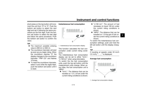
NOTICE
ECA11401
Use only unleaded gasoline. The use
of leaded gasoline will cause severe
damage to internal engine parts,
such as the valves and piston rings,
as well as to the exhaust system.
TIPThis mark identifies the recom-
mended fuel for this vehicle as
specified by European regulation
(EN228).
Check that gasoline nozzle has
the same identifier when fueling.Your Yamaha engine has been de-
signed to use regular unleaded gaso-
line with a research octane number of
95 or higher. If knocking (or pinging)
occurs, use a gasoline of a different
brand or premium unleaded fuel. Use
of unleaded fuel will extend spark plug
life and reduce maintenance costs.Gasohol
There are two types of gasohol: gaso-
hol containing ethanol and that con-
taining methanol. Gasohol containing
ethanol can be used if the ethanol con-
tent does not exceed 10% (E10). Gas-
ohol containing methanol is not
recommended by Yamaha because it
can cause damage to the fuel system
or vehicle performance problems.
Recommended fuel:
Premium unleaded gasoline (E10
acceptable)
Fuel tank capacity:
16 L (4.2 US gal, 3.5 Imp.gal)
Fuel reserve amount:
4.3 L (1.14 US gal, 0.95 Imp.gal)
E5
E10
UBW3E0E0.book Page 18 Friday, May 24, 2019 11:01 AM
Page 34 of 102

Instrument and control functions
3-19
3
EAU80200
Fuel tank overflow hoseBefore operating the vehicle:
Check the fuel tank overflow hose
connection.
Check the fuel tank overflow hose
for cracks or damage, and replace
it if necessary.
Make sure that the end of the fuel
tank overflow hose is not blocked,
and clean it if necessary.
Make sure that the end of the fuel
tank overflow hose is positioned
as shown.TIPSee page 6-10 for canister information.
EAU13435
Catalytic converterThe exhaust system contains catalytic
converter(s) to reduce harmful exhaust
emissions.
WARNING
EWA10863
The exhaust system is hot after op-
eration. To prevent a fire hazard or
burns:
Do not park the vehicle near
possible fire hazards such as
grass or other materials that
easily burn.
Park the vehicle in a place
where pedestrians or children
are not likely to touch the hot
exhaust system.
Make sure that the exhaust sys-
tem has cooled down before
doing any maintenance work.
Do not allow the engine to idle
more than a few minutes. Long
idling can cause a build-up of
heat.
EAUM4110
SeatsPassenger seat
To remove the passenger seat1. Insert the key into the seat lock,
and then turn the key counter-
clockwise.
2. Lift the rear of the passenger seat
and pull it backward.
1. Canister breather hose
1
1. Seat lock
2. Unlock.
3. Passenger seat
2
13
UBW3E0E0.book Page 19 Friday, May 24, 2019 11:01 AM
Page 35 of 102

Instrument and control functions
3-20
3 To install the passenger seat
1. Insert the projection on the front of
the passenger seat into the seat
holder as shown, and then push
the rear of the seat down to lock it
in place.
2. Remove the key.
Rider seat
To remove the rider seat1. Remove the passenger seat, and
then remove the hexagon wrench
located on the rear of the rider
seat.2. Remove the bolts with the hexa-
gon wrench.
3. Lift the rear of the rider seat and
pull it backward.To install the rider seat
1. Insert the projection on the front of
the rider seat into the seat holder
as shown, and then place the seat
in the original position.
2. Install the bolts with the hexagon
wrench.
3. Insert the hexagon wrench back
into its holder on the rider seat.
4. Install the passenger seat.TIPMake sure that the seats are properly
secured before riding.
1. Projection
2. Seat holder
12
1. Hexagon wrench
1. Bolt
1
1
1. Projection
2. Slot1 2
UBW3E0E0.book Page 20 Friday, May 24, 2019 11:01 AM
Page 36 of 102

Instrument and control functions
3-21
3
EAU39612
Adjusting the headlight beamsThe headlight beam adjusting knobs
are used to raise or lower the height of
the headlight beams. It may be neces-
sary to adjust the headlight beams to
increase visibility and help prevent
blinding oncoming drivers when carry-
ing more or less load than usual. Obey
local laws and regulations when ad-
justing the headlights.
To raise the headlight beams, turn the
knobs in direction (a). To lower the
headlight beams, turn the knobs in di-
rection (b).
EAU45205
Adjusting the front fork
WARNING
EWA10181
Always adjust both fork legs equally,
otherwise poor handling and loss of
stability may result.This front fork is equipped with re-
bound damping force adjusting screws
and compression damping force ad-
justing screws.NOTICE
ECA10102
To avoid damaging the mechanism,
do not attempt to turn beyond the
maximum or minimum settings.Rebound damping force
Turn the adjusting screw in direction (a)
to increase the rebound damping
force.
Turn the adjusting screw in direction (b)
to decrease the rebound damping
force.
To set the rebound damping force, turn
the adjuster in direction (a) until it
stops, and then count the clicks in di-
rection (b).
TIPWhen turning the damping force
adjuster in direction (a), the 0 click
position and the 1 click position
may be the same.
When turning the damping force
adjuster in direction (b), it may
click beyond the stated specifica-
1. Headlight beam adjusting knob
(a)
(a) (b)
(b)
1
1. Rebound damping force adjusting screwRebound damping setting:
Minimum (soft):
31 click(s) in direction (b)
Standard:
17 click(s) in direction (b)
Maximum (hard):
0 click(s) in direction (b)
1
(b)(a)
UBW3E0E0.book Page 21 Friday, May 24, 2019 11:01 AM
Page 37 of 102

Instrument and control functions
3-22
3 tions, however such adjustments
are ineffective and may damage
the suspension.
Compression damping force
1. Remove the rubber cap by pulling
it out of the front fork leg.
2. Turn the adjusting screw in direc-
tion (a) to increase the compres-
sion damping force. Turn the
adjusting screw in direction (b) to
decrease the compression damp-
ing force. To set the compression
damping force, turn the adjuster in
direction (a) until it stops, and then
count the clicks in direction (b).3. Install the rubber cap.
TIPWhen turning the damping force
adjuster in direction (a), the 0 click
position and the 1 click position
may be the same.
When turning the damping force
adjuster in direction (b), it may
click beyond the stated specifica-tions, however such adjustments
are ineffective and may damage
the suspension.
1. Rubber cap1
1. Compression damping force adjusting
screw
Compression damping setting:
Minimum (soft):
22 click(s) in direction (b)
Standard:
11 click(s) in direction (b)
Maximum (hard):
0 click(s) in direction (b)1(a) (b)
UBW3E0E0.book Page 22 Friday, May 24, 2019 11:01 AM
Page 38 of 102

Instrument and control functions
3-23
3
EAU14796
Front fork bleedingWhen riding in extremely rough condi-
tions, the air temperature and pressure
in the front fork will rise and harden the
suspension. If this occurs, bleed the air
from each fork leg.
WARNING
EWA10201
Always bleed both fork legs, other-
wise poor handling and loss of sta-
bility may result.1. If possible, elevate the vehicle so
the front wheel is off the ground.
(See page 6-34.)TIPWhen bleeding the front fork, do not
apply any pressure or weight on the
front end of the vehicle.2. Remove the bleed screws and al-
low all of the air to escape from
each fork leg.3. Install the bleed screws.
4. Lower the front wheel so that it is
on the ground, and then put the
sidestand down.
EAUM4120
Adjusting the shock absorber
assemblyThis shock absorber assembly is
equipped with a spring preload adjust-
er and rebound and compression
damping force adjusters.NOTICE
ECA10102
To avoid damaging the mechanism,
do not attempt to turn beyond the
maximum or minimum settings.Spring preload
Turn the adjuster in direction (a) to in-
crease the spring preload.
Turn the adjuster in direction (b) to de-
crease the spring preload.
1. Bleed screw
1
1. Spring preload adjusting knob
1
(b)(a)
UBW3E0E0.book Page 23 Friday, May 24, 2019 11:01 AM
Page 39 of 102
, the 0 click
position and the 1 click position
may be the same.
When turning the spring prelo")
Instrument and control functions
3-24
3
TIPWhen turning the spring preload
adjuster in direction (b), the 0 click
position and the 1 click position
may be the same.
When turning the spring preload
adjuster in direction (a), it may
click beyond the stated specifica-
tions, however such adjustments
are ineffective and may damage
the suspension.Rebound damping force
Turn the adjuster in direction (a) to in-
crease the rebound damping force.
Turn the adjuster in direction (b) to de-
crease the rebound damping force.To set the rebound damping force, turn
the adjuster in direction (a) until it
stops, and then count the clicks in di-
rection (b).
TIPWhen turning the damping force
adjuster in direction (a), the 0 click
position and the 1 click position
may be the same.When turning the damping force
adjuster in direction (b), it may
click beyond the stated specifica-
tions, however such adjustments
are ineffective and may damage
the suspension.
Compression damping force
Turn the adjuster in direction (a) to in-
crease the compression damping
force.
Turn the adjuster in direction (b) to de-
crease the compression damping
force.
To set the compression damping
force, turn the adjuster in direction (a)
until it stops, and then count the clicks
in direction (b).
Spring preload setting:
Unit for adjustment:
Click
Minimum (soft):
0
Standard:
10
Maximum (hard):
24
1. Rebound damping force adjusting screw
Rebound damping setting:
Unit for adjustment:
Click
Minimum (soft):
23
Standard:
13
Maximum (hard):
0
1
(b)(a)
1. Compression damping force adjusting
screw
1
(b)(a)
UBW3E0E0.book Page 24 Friday, May 24, 2019 11:01 AM
Page 40 of 102
, the 0 click
position and the 1 click position
may be the same.
When turning the damping force")
Instrument and control functions
3-25
3
TIPWhen turning the damping force
adjuster in direction (a), the 0 click
position and the 1 click position
may be the same.
When turning the damping force
adjuster in direction (b), it may
click beyond the stated specifica-
tions, however such adjustments
are ineffective and may damage
the suspension.
WARNING
EWA10222
This shock absorber assembly con-
tains highly pressurized nitrogen
gas. Read and understand the fol-
lowing information before handling
the shock absorber assembly.Do not tamper with or attempt
to open the cylinder assembly.
Do not subject the shock ab-
sorber assembly to an open
flame or other high heat source.
This may cause the unit to ex-
plode due to excessive gas
pressure.
Do not deform or damage the
cylinder in any way. Cylinder
damage will result in poor
damping performance.
Do not dispose of a damaged or
worn-out shock ab
sorber as-
sembly yourself. Take the shock
absorber assembly to a Yamaha
dealer for any service.
EAU84680
Luggage strap holdersUse the indicated strap points to se-
cure luggage ties to the vehicle.
Compression damping setting:
Unit for adjustment:
Click
Minimum (soft):
18
Standard:
15
Maximum (hard):
0
1. Luggage strap holder
1
UBW3E0E0.book Page 25 Friday, May 24, 2019 11:01 AM