Page 33 of 100

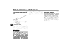
Instrument and control functions
3-18
3
Make sure that the fuel tank over-
flow hose is routed through the
clamp.
Make sure that the paint mark on
the fuel tank overflow hose is be-
low the clamp.
EAU13434
Catalytic converterThis model is equipped with a catalytic
converter in the exhaust system.
WARNING
EWA10863
The exhaust system is hot after op-
eration. To prevent a fire hazar d or
b urns:
Do not park the vehicle near
possi ble fire hazar ds such as
g rass or other materials that
easily burn.
Park the vehicle in a place
where pe destrians or chil dren
are not likely to touch the hot
exhaust system.
Make sure that the exhaust sys-
tem has cooled down before
d oin g any maintenance work.
Do not allow the en gine to id le
more than a few minutes. Lon g
i d lin g can cause a buil d-up of
heat.
NOTICE
ECA10702
Use only unlea ded g asoline. The use
of lea ded g asoline will cause unre-
paira ble damag e to the catalytic
converter.
UB4CE1E0.book Page 18 Friday, August 3, 2018 10:57 AM
Page 34 of 100
Instrument and control functions
3-19
3
EAU83850
SeatsPassen ger seat
To remove the passenger seat1. Insert the key into the seat lock, and then turn it counterclockwise.
2. While holding the key in that posi- tion, lift the rear of the passenger
seat and pull it backward. To install the passenger seat
1. Insert the projections on the front
of the passenger seat into the seat
holders as shown, and then push
the rear of the seat down to lock it
in place.
2. Remove the key.
Ri der seat
To remove the rider seat1. Remove the passenger seat, and then remove the hexagon wrench
located on the bottom of the seat. 2. Remove the bolts with the hexa-
gon wrench.
3. Lift the seat rearward and up to re- move it.
1. Seat lock
2. Unlock.
2
1
1. Projection
2. Seat holder
1
2
1. Passenger seat
2. Hexagon wrench
1. Bolt
1
2
1
UB4CE1E0.book Page 19 Friday, August 3, 2018 10:57 AM
Page 35 of 100

Instrument and control functions
3-20
3
To install the rider seat
1. Fit the slot in the seat onto the pro-
jection on the frame cross mem-
ber as shown, and then place the
seat in the original position.
2. Install the bolts with the hexagon wrench.
3. Insert the hexagon wrench back into its holder on the passenger
seat.
4. Install the passenger seat.TIPMake sure that the seats are properly
secured before riding.
EAU59981
Helmet hol din g ca bleA helmet holding cable is located on
the bottom of the passenger seat. Use
this cable in conjunction with the
screwdriver to secure a helmet to the
vehicle.
To secure a helmet with the helmet
hol din g cab le
1. Remove the passenger seat. (See page 3-19.)
2. Remove the screwdriver from its holders on the passenger seat,
and then remove the helmet hold-
ing cable from the screwdriver.
TIPWhen removing the screwdriver, slide
the screwdriver toward the “ ” mark
on the passenger seat.3. Pass the helmet holding cablethrough the buckle on the helmet
strap.
4. Hook the cable loops over the screwdriver, install the screw-
driver by first inserting the screw-
driver into the holder with the “ ”
mark, and then slide the screw-
driver toward the holder with
the “ ” mark.
1. Slot
2. Projection
1
2
1. Passenger seat
2. Helmet holding cable
3. Screwdriver1
2
3
1. Screwdriver
2. “ ” mark
3. “ ” mark
1
2
3
UB4CE1E0.book Page 20 Friday, August 3, 2018 10:57 AM
Page 36 of 100

Instrument and control functions
3-21
3
TIPMake sure that the screwdriver is se-
curely positioned between its holders,
and then position the cable loops to-
ward the middle of the screwdriver be-
fore installing the passenger seat.5. Install the passenger seat.
WARNING! Never ri de with a
helmet attached to the helmet
hol der, since the helmet may hit
o bjects, causin g loss of control
an d possi bly an acci dent.
[EWA10162]
To release a helmet from the helmet
hol din g cab le
1. Remove the passenger seat.
2. Remove the screwdriver, then re- move the helmet holding cable
from the helmet.
3. Store the cable under the seat by hooking the cable loops over the
screwdriver, install the screw-
driver in its original position, and
then hook the helmet holding ca-
ble over the hook on the bottom of
the passenger seat.
4. Install the passenger seat.
EAU84080
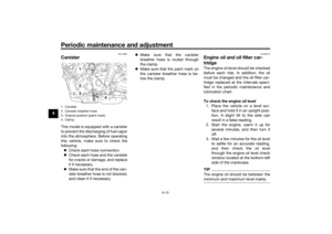
Stora ge compartmentThe storage compartment is located as
shown.
1. Helmet
2. Helmet holding cable
3. Screwdriver
4. Holder
1
2
3
4
1. Screwdriver
2. Helmet holding cable
3. Hook1
2
3
1. Storage compartment cover
1. Storage compartment
11
UB4CE1E0.book Page 21 Friday, August 3, 2018 10:57 AM
Page 37 of 100

Instrument and control functions
3-22
3
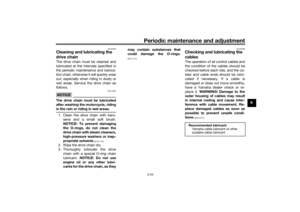
When storing documents, wrap them
in a plastic bag so they will not get wet.
When washing the vehicle, avoid
spraying water directly under the seat.
WARNING
EWA15401
Do not exceed
the maximum loa d of
172 k g (379 l b) for the vehicle.
EAU57943
A djustin g the shock a bsor ber
assem blyThis shock absorber assembly is
equipped with a spring preload adjust-
ing ring and a rebound damping force
adjusting screw.NOTICE
ECA10102
To avoi d d amag ing the mechanism,
d o not attempt to turn b eyond the
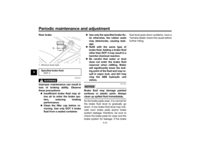
maximum or minimum settin gs.Sprin g preloa d
To increase the spring preload and
thereby harden the suspension, turn
the adjusting ring in direction (a). To
decrease the spring preload and there-
by soften the suspension, turn the ad-
justing ring in direction (b).
Align the appropriate notch in the
adjusting ring with the position in-
dicator on the shock absorber.
Use the special wrench and ex-
tension bar in the tool kit to make
this adjustment.
1. Extension bar
2. Special wrench
3. Spring preload adjusting ring
4. Position indicator
Sprin g preloa d settin g:
Minimum (soft): 1
Standard: 4
Maximum (hard):
7
76
54321
3
(b)(a)
2
1
4
UB4CE1E0.book Page 22 Friday, August 3, 2018 10:57 AM
Page 38 of 100
. To decrease t")
Instrument and control functions
3-23
3 Re
boun d d ampin g force
To increase the rebound damping
force and thereby harden the rebound
damping, turn the adjusting screw in
direction (a). To decrease the rebound
damping force and thereby soften the
rebound damping, turn the adjusting
screw in direction (b).
TIP When adjusting the damping force
settings, turn the adjuster in direc-
tion (a) until it stops, and then
count the turns in direction (b).
Although a damping force adjust-
er may turn beyond the stated
minimum settings, such adjust-
ments are ineffective and may
damage the suspension.
WARNING
EWA10222
This shock a bsor ber assem bly con-
tains hi ghly pressurize d nitro gen
g as. Rea d an d un derstan d the fol-
lowin g information b efore handlin g
the shock a bsor ber assem bly.
Do not tamper with or attempt
to open the cylin der assem bly.
Do not su bject the shock a b-
sor ber assem bly to an open
flame or other hi gh heat source.
This may cause the unit to ex-
plo de due to excessive gas
pressure.
Do not deform or d amage the
cylin der in any way. Cylin der
d amag e will result in poor
d ampin g performance.
Do not d ispose of a damag ed or
worn-out shock a bsor ber as-
sem bl
y yourself. Take the shock
a b sor ber assem bly to a Yamaha
d ealer for any service.
1. Rebound damping force adjusting screwRe boun d d ampin g setting :
Minimum (soft): 3 turn(s) in direction (b)
Standard: 1.5 turn(s) in direction (b)
Maximum (hard):
0 turn(s) in direction (b)
1(a)(b)
UB4CE1E0.book Page 23 Friday, August 3, 2018 10:57 AM
Page 39 of 100
Instrument and control functions
3-24
3
EAU85220
Lu gga ge strap hol dersUse the indicated strap points to se-
cure luggage to the vehicle. To use the luggage strap holders under
the passenger seat, remove the pas-
senger seat (3-19), remove the straps
from their hooks, and then install the
seat with the straps hanging out.
EAU70641
Auxiliary DC connectorThis vehicle is equipped with an auxil-
iary DC connector. Consult your
Yamaha dealer before installing any
accessories.
1. Luggage strap holder
2. Hook
1. Luggage strap holder
12
2
11
UB4CE1E0.book Page 24 Friday, August 3, 2018 10:57 AM
Page 40 of 100

Instrument and control functions
3-25
3
EAU15306
Si destan dThe sidestand is located on the left
side of the frame. Raise the sidestand
or lower it with your foot while holding
the vehicle upright.TIPThe built-in sidestand switch is part of
the ignition circuit cut-off system,
which cuts the ignition in certain situa-
tions. (See the following section for an
explanation of the ignition circuit cut-
off system.)
WARNING
EWA10242
The vehicle must not be ri dden with
the si destan d d own, or if the si de-
stan d cannot b e properly move d up
(or does not stay up), otherwise the
si destan d coul d contact the groun d
an d d istract the operator, resultin g
in a possi ble loss of control.
Yamaha’s ig nition circuit cut-off
system has been desi gne d to assist
the operator in fulfillin g the respon-
si bility of raisin g the si destan d b e-
fore startin g off. Therefore, check this system re
gularly an d have a
Yamaha dealer repair it if it does not
function properly.
EAU44895
I g nition circuit cut-off systemThis system prevents in-gear engine
starts unless the clutch lever is pulled
and the sidestand is up. Also, it will
stop the running engine should the
sidestand be lowered while the trans-
mission is in gear.
Periodically check the system via the
following procedure.TIP This check is most reliable if per-
formed with a warmed-up engine.
See pages 3-2 and 3-12 for switch
operation information.
UB4CE1E0.book Page 25 Friday, August 3, 2018 10:57 AM