2020 VOLKSWAGEN TRANSPORTER warning lights
[x] Cancel search: warning lightsPage 142 of 486

Never connect the trailer lights directly to the elec-trical system of your vehicle. If you are uncertain whether the trailer has been connected correctly, please contact a qualified workshop. Volkswagen Commercial Vehicles recommends using a Volks-wagen Commercial Vehicles dealership for this purpose.
Exterior mirrors
If you are unable to see the traffic behind the trailer in the vehicle's standard exterior mirrors, additional exterior mirrors should be fitted in accordance with any country-specific regulations. Before setting off, adjust the mirrors so that you have a sufficient view of the rear.
Maximum power consumption of the trailer
Electrical consumers Maximum output
All brake lights 84 watts
Turn signal per side 42 watts
All side lights 100 watts
All tail lights 42 watts
Rear fog light 42 watts
Never exceed the specified values.
A wARNING
If the towing bracket is unsuitable or is in cor-rectly fitted, the trailer can become detached from the vehicle and cause serious Injury.
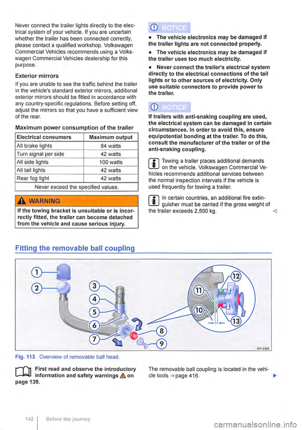
Fitting the removable ball coupling
Fig. 113 Overview of removable ball head.
r-f1t First read and observe the introductory L-J,::,JJ information and safety warnings & on page 139.
1421 Before the journey
• The vehicle electronics may be damaged If the trailer uses too much electricity.
• Never connect the trailer's electrical system directly to the electrical connections of the tail lights or to other sources of electricity. Only use suitable connectors to provide power to the trailer.
m Towing a trailer places additional demands L!J on the vehicle. Volkswagen Commercial Ve-hicles recommends additional services between the normal inspection intervals if the vehicle is used frequently for towing a trailer.
m In certain countries, an additional fire extin-L!J guisher must be carried if the gross weight of the trailer exceeds 2,500 kg. <1
an.ons
The removable ball coupling is located in the vehi-cle tools 416. ..,.
Page 145 of 486

Key to diagram Fig. 114:
Pin Meaning
8 Reversing light
9 Permanent live
10 Charging cable plus
11 Earth pin 10, charging cable
12 Not assigned
13 Earth pin 9, permanent live
Trailer socket
A 13-pin trailer socket makes the electrical connec-tion between the towing vehicle and the trailer. When the engine is running, electrical consumers in the trailer are supplied with voltage (charging ca-ble) via the electrical connection (pin 10 of the trail-er socket). If required, the charging cable charges the caravan's battery.
When a trailer is electrically detected, electrical consumers in the trailer are supplied with voltage (permanent live) via the electrical connection (pin 9). Permanent live supplies a trailer's interior lighting for example. Electrical consumers such as a caravan refrigerator are supplied with voltage on-ly when the engine is running (pin 1 0).
To avoid overloading the electrical system, do not inter-connect the three earth wires (pins 3, 11 and 13).
If the trailer has a 7 -pin plug you will need to use a suitable adapter cable. Pin 10 (charging cable) is then without function.
Emergency breakaway cable
Always fasten the trailer's emergency breakaway cable properly to the towing vehicle. Leave enough slack in the emergency breakaway cable so that the vehicle can still drive around corners. However the emergency breakaway cable should not drag along the ground while you are driving.
Trailer rear lights
Ensure that the trailer lights work properly and meet legal requirements. Do not exceed the maxi-mum power consumption for the trailer 142.
Connection to the anti-theft alarm
The trailer is integrated in the anti-theft system if the following conditions are fulfilled:
• When the vehicle has a factory-fitted anti-theft alarm and a factory-fitted towing bracket.
• When the trailer is electrically connected to the towing vehicle via the trailer socket.
• When the vehicle and trailer electric systems are functional, fault-free and undamaged.
• When the vehicle is locked with the vehicle key and the anti-theft alarm is active.
When the vehicle is locked, the alarm will be trig-gered as soon as the electrical connection to the trailer is interrupted.
Always switch off the anti-theft alarm when a trailer is being hitched or unhitched. The tilt sensor could otherwise trigger an alarm unnecessarily.
Trailer with LED rear lights
For technical reasons, trailers with LED tail lights cannot be integrated into the anti-theft alarm sys-tem.
When the vehicle is locked, the alarm is not trig-gered as soon as the electrical connection to the trailer with LED rear lights is interrupted.
A WARNING
Any electrical cables that are not connected properly could cause a power surge to the trailer. This could cause faults tn the entire vehicle electronics system and also lead to accidents and serious Injuries.
• All work on the electric system should be carried out by a qualified workshop.
• Never connect the trailer's electrical sys-tem directly to the electrical connections of the tail lights or to other sources of electrici-ty.
CD
If you park the trailer using the support wheel or other trailer supports, disconnect the trailer from the vehicle. The vehicle could rock up and down if the load changes or if there is damage to the tyres. If this happens, a great deal of force will be exerted on the towing bracket and trailer, which could lead to damage to the vehi-cle and trailer.
CD
Maximum power consumption of the trailer should not be exceeded. Otherwise, the vehicle electrical system could be damaged.
m If there is a fault in the vehicle or trailer elec-L.:!.J trical systems or in the anti-theft alarm, have the systems checked by a qualified workshop.
m If the engine is not running and electrical L.:!.J equipment is switched on in the trailer via the trailer socket, the vehicle battery will discharge. .,.
Transporting Items 145
Page 149 of 486

Retrofitting a towing bracket
Fig. 115 Dimensions and attachment points for retrofitting a towing bracket.
r-1"'11 First read and observe the Introductory L-J,:.U Information and safety warnings & on page 139.
Volkswagen Commercial Vehicles recommends having the towing bracket retrofitted by a qualified workshop. Volkswagen Commercial Vehicles rec-ommends using a Volkswagen Commercial Vehi-cles dealership for this purpose. Electronic compo-
nents also have to be retro-fitted and, for example, the cooling system may need to be modified or heat shields may need to be fitted. For this and other work, specialist knowledge and tools are re-quired.
=>Fig. 115 shows the dimensions and attachment points which must be observed if you have a tow-ing bracket retro-fitted. Always observe the mini-mum distance given from the middle of the ball coupling to the surface of the road. This also ap-plies when the vehicle Is fully laden, including max-imum drawbar load.
The attachment points ® are underneath the vehi-cle.
The trailer stabilisation system can be activated if a towing bracket is retrofitted, provided compatible electronic components are fitted. Volkswagen Commercial Vehicles recommends using a Volks-wagen Commercial Vehicles dealership for this purpose.
A WARNING
Electrical accessories that are not connected properly can cause faults In the entire vehicle electronics system and also cause accidents and serious Injuries.
• Never connect the trailer's electrical sys-tem directly to the electrical connections of the tall lights or to other unsuitable sources of electricity. Only a suitable connector may be used to connect the trailer.
• A towing bracket should be retrofitted to the vehicle by a qualified workshop.
A WARNING
The trailer can become detached from the towing vehicle if the towing bracket Is unsuit-able or Incorrectly fitted. This can cause seri-ous accidents and fatal injuries.
r::l Only use towing brackets which have been W approved by Volkswagen Commercial Vehi-cles for your vehicle type.
Page 161 of 486

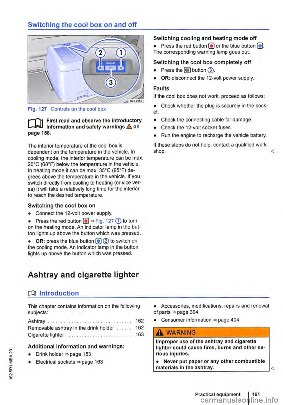
Switching the cool box on and off
Fig. 127 Controls on the cool box
r-f'n First read and observe the Introductory Information and safety warnings & on page 158.
The interior temperature of the cool box is dependent on the temperature in the vehicle. In cooling mode, the interior temperature can be max. 20•c (68°F) below the temperature in the vehicle. In heating mode it can be max. 35•c (95.F) de-grees above the temperature in the vehicle. If you switch directly from cooling to heating (or vice ver-sa) it will take a relatively long time for the interior to reach the desired temperature.
Switching the cool box on
• Connect the 12-volt power supply.
• Press the red Fig. 127 G) to turn on the heating mode. An indicator lamp in the but-ton lights up above the button which was pressed.
• OR: press the blue button (!)®to switch on the cooling mode. An indicator lamp in the button lights up above the button which was pressed.
Ashtray and cigarette lighter
o:n Introduction
This chapter contains information on the following subjects:
Ashtray . . . . . . . . . . . . . . . . . . . 162
Removable ashtray in the drink holder 162
Cigarette lighter . . . . . . . . . . . . . . . . . . . 163
Additional information and warnings:
• Drink holder 153
• Electrical sockets 163
Switching cooling and heating mode off
• Press the red button(!) or the blue button (!). The corresponding warning lamp goes out.
Switching the cool box completely off
• Press the@) button @.
• OR: disconnect the 12-volt power supply.
Faults
If the cool box does not work, proceed as follows:
• Check whether the plug is securely in the sock-et.
• Check the connecting cable for damage.
• Check the 12-volt socket fuses.
• Run the engine to recharge the vehicle battery.
If these steps do not help, contact a qualified work-shop.
• Consumer information 404
A WARNING
Improper use of the ashtray and cigarette lighter could cause fires, burns and other se-rious Injuries.
• Never put paper or any other combustible materials In the ashtray.
Page 165 of 486

A DANGER (Continued)
• 230-volt socket with inverter switch:
CD
-Do not plug adapters or extension ca-bles into the 230-volt socket. Otherwise the built-in child lock will disengage and power will be supplied to the socket.
• Observe the operating instructions for any device that you plug into the socket.
• Never exceed the maximum power rating as this could damage the whole vehicle electrical system.
• Only use accessories that have been ap-proved in accordance with valid guidelines concerning electromagnetic compatibility.
CD
• Never feed electricity Into the socket.
• Do not plug any heavy devices or connec-tions, such as mains adapters, directly Into the socket.
• Only connect devices to the socket with a voltage that matches the voltage of the socket.
• 230-volt socket with inverter switch:
-Do not connect any lights which use neon tubes.
-With electrical devices that require a high level of current In the start phase, the built-In excess current switch will prevent the de-vice from being switched on. If this hap-pens, disconnect the device from the power supply and reconnect after waiting approxi-mately 10 seconds.
m Unshielded devices can cause interference W with radio reception and vehicle electronics.
[Q) Introduction
This chapter contains information on the following subjects:
Components ......... .
Folding the LCD screen out and in
DVD player ..
Controls on the LCD screen ...
Remote control ..
Settings on the LCD screen Settings on the DVD player
Care and protection
166
167 167
168
169
170 171
Use a suitable screen cleaner for cleaning the screen Be careful not to scratch the screen when cleaning it.
A WARNING
Improper use of the rear seat entertainment system could cause short-circuits, fire and serious Injuries.
• Protect the rear seat entertainment system against moisture and damp.
A WARNING
Objects that are loosely placed in the vehicle or not properly secured could be flung through the interior and cause injuries during a sudden driving or braking manoeuvre, or in the event of an accident.
• Always stow the remote control units and headsets securely In the stowage compart-ments.
A WARNING
Accidents and Injuries can occur If the driver Is distracted.
• Never allow use of the rear seat entertain-ment system to distract you from what Is happening on the road.
• Comply with legal regulations .
• Select volume settings that allow signals from outside the vehicle (such as emergency services sirens) to be easily heard at all times.
Practical equipment 165
Page 187 of 486

Switching on the refrigerator box
• Slide the cover open =>Fig. 149 (D.
• Move switch =>Fig. 150 CD to I position. When the refrigerator box is switched on, the lamp in the box lights up.
• Fill the refrigerator box and then close the lid =>&.
Switching off the refrigerator box
• Slide the cover open =>Fig. 149 (D.
• Move switch =>Fig. 150 CD to 0 position. The in-dicator lamp in the refrigerator box goes out.
• Close the cover.
Notes on cleaning and care
Clean the refrigerator box thoroughly before using it for the first time, if it is dirty or if it has not been used for a long time.
To avoid stains and mildew in the refrigerator box if it remains unused for a long time, leave the cover slightly open.
• Use water and normal household cleaning fluid to clean the refrigerator box.
• The refrigerator box should be defrosted regu-larly to prevent layers of ice forming. To do this, switch the refrigerator box off and leave the cover open. Do not use an additional heat source to de-frost the refrigerator more quickly. This could dam-age the refrigerator =>
If the refrigerator box is left on when the engine is not running, the additional battery runs down. The refrigerator box is therefore fitted with a battery monitor. The battery monitor will switch the refriger-ated box off if the charge of the additional battery becomes too low. The battery monitor will switch the refrigerator box on again as soon as the addi-tional battery has reached a suitable charge level, for example, after a long journey.
Rear-seat telephony, Business
a:n Introduction
This chapter contains information on the following subjects:
Components . . . . . . . . . . . . . . . . . . . . . . . . . . . . 189
Pairing a mobile telephone before using it for the first time . . . . . . . . . 190
Functional description ........... . 190
A WARNING
Objects that are not secured, or are secured incorrectly, can cause serious injuries in the event of a sudden driving or braking manoeu-vre or accident.
• The refrigerator box lid must always be kept closed and locked when the vehicle is in motion.
• Never use the refrigerator box as a table or stowage compartment when the vehicle is In motion.
A WARNING
If the ambient temperature In the vehicle Is too low, the temperature in the refrigerator box could fall below +2 •c {+35 °F) degrees. ThIs could cause the contents of the refriger-ator box to freeze and bottles and other con-tainers to burst, potentially causing Injuries.
• Do not use the refrigerator box when the ambient temperature Is too low.
CD
Handling the refrigerator box incorrectly could damage it.
• Do not place containers, food or other ob-jects which are warmer than +50 •c (+122 •F) In the refrigerator box.
• Do not place corrosive substances or sol-vents in the refrigerator box.
• Do not use an additional heat source to de-frost the refrigerator box.
m The refrigerator box is not suitable for cooling W the vehicle interior. The refrigerator box should only be used to keep food cool and for transporting heat-sensitive items on short journeys.
The rear-seat telephony system (hands-free sys-tem in the passenger compartment with Private Mode) works independently of other provision for mobile telephones fitted in the vehicle. Neither the
Equipment, Business 1187
Page 206 of 486

Symbol Meaning
A Flow of electric current in amps
Lit up: 230-volt mains connection has been made and the battery charger is working. Flashing or displaying a number over 15 volts: malfunction. Disconnect the 230-volt mains connection and have the electrical system checked by a qualified workshop. Not lit up despite a 230-volt connection being made: there is a power cut or malfunction in the battery charger.
G The batteries are being charged by the alternator.
Warning messages
Under certain conditions, such as when the pop-up roof is open, warning messages appear on the dis-play when the engine is started. These warn against possible vehicle or equipment damage.
• Switch off the ignition and correct the cause of the warning message.
Malfunction
If a symbol flashes, there is a fault in the indicated system.
• Press the button G?) for five seconds to clear the fault. If this does not work or if other faults ap-pear, please contact a qualified workshop. Volks-wagen Commercial Vehicles recommends using a Volkswagen Commercial Vehicles dealership for this purpose.
A WARNING
Failure to observe illuminated warning lamps and text messages can lead to your vehicle breaking down in traffic, and can cause acci-dent and serious injury.
A WARNING (Continued)
• Never Ignore any Illuminated warning lamps or text messages.
• Stop the vehicle as soon as possible and when safe to do so.
• Stop the vehicle at a safe distance away from moving traffic and ensure that no part of the exhaust system can come Into contact with any Inflammable material underneath the vehicle, e.g. dry grass or fuel.
• Any broken-down vehicle poses an In-creased accident risk both for you and for other road users. If the situation requires, switch on the hazard warning lights and set up the warning triangle as a warning to other road users.
• Before opening the bonnet, switch off the engine and allow it to cool down sufficiently.
• The engine compartment of any motor ve-hicle is a dangerous area. Serious injuries can be sustained here 350.
CD
Failure to observe illuminated indicator lamps and text messages can lead to your vehicle be-ing damaged.
J'"'""'('n First read and observe the introductory L-J,:.IJ information given on page 204.
Main menu Possible functions
Pop-up roof Opening
Closing
Displays Outside temperature
206 Before the journey
Using the menus
• Turn the rotary/push knob 168@ to highlight a function or submenu or to change a set-ting.
• Press the rotary/push knob to select a function or submenu or to confirm a setting.
Description of the submenu with examples
Open the pop-up roof .,1
Close the pop-up roof .,t
Current outside temperature (28.SO C) ...
Page 210 of 486

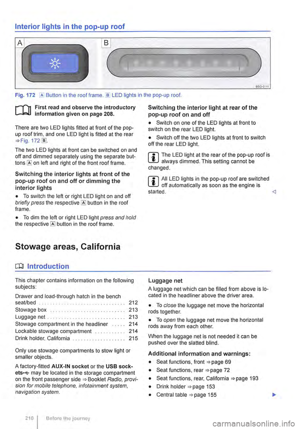
Interior lights in the pop-up roof
___ )
Fig. 172 ,A Button in the roof frame . ..!!. LED lights in the pop-up roof.
r--T'n First read and observe the introductory L-lcJ.I information given on page 208.
There are two LED lights fitted at front of the pop-up roof trim, and one LED light is fitted at the rear =?Fig. 172 [ID.
The two LED lights at front can be switched on and off and dimmed separately using the separate but-on left and right of the front roof frame.
Switching the interior lights at front of the pop-up roof on and off or dimming the interior lights
• To switch the left or right LED light on and off briefly press the button in the roof frame.
• To dim the left or right LED light press and hold the button in the roof frame.
Stowage areas, California
CQJ Introduction
This chapter contains information on the following subjects:
Drawer and load-through hatch in the bench seaVbed . . . . . . . . . . . . . . . . 212
Stowage box . . . . . . . . . . . . . . . . . . . 213 Luggage net .. .. .. . .. .. . 213
Stowage compartment in the headliner . . . . . 214 Lockable stowage compartment . . 214 Drink holder, California . . . . . . . . . . . 215
Only use stowage compartments to stow light or smaller objects.
A factory-fitted AUX-IN socket or the USB sock-ets-may be located in the storage compartment on the front passenger side =?Booklet Radio, provi-sion for mobile telephone, infotainment system, navigation system.
210 I Before the journey
Switching the interior light at rear of the pop-up roof on and off
• Switch on one of the LED lights at front to switch on the rear LED light.
• Switch off the two LED lights at front to switch off the rear LED light.
m The LED light at the rear of the pop-up roof is W always dimmed. This setting cannot be changed.
m All LED lights in the pop-up roof are switched W off automatically as soon as the engine is started.
A luggage net which can be filled from above is lo-cated in the headliner above the driver area.
• To close the luggage net move the horizontal rods together.
• To open the luggage net move the horizontal rods away from each other.
When the luggage net is not needed it can be pushed over the slatted blind.
Additional information and warnings:
• Seat functions, front =?page 69
• Seat functions, rear =?page 72
• Seat functions, rear, California =?page 193
• Drink holder =?page 153
• Central table =?page 155