2020 MERCEDES-BENZ GLS SUV wheel
[x] Cancel search: wheelPage 410 of 549
#
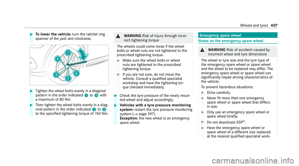
Tolowe r the vehicle: turnthera tchet ring
spanner of the jack anti-clockwise. #
Tighten the wheel bolts evenly in a diagonal
pattern in the order indicated 1to5 with
a maximum of 80 Nm. #
Then tighten the wheel bolts evenly in a diag‐
onal pattern in the order indicated 1to5
to the specified tightening torque of 150 Nm. &
WARNING Risk of inju rythro ugh incor‐
re ct tigh tening torque
The wheels could come loose if the wheel
bolts or wheel nuts are not tightened tothe
prescribed tightening torque. #
Makesure the wheel bolts or wheel
nuts are tightened tothe prescribed
tightening torque. #
Ifyo u are not sure, do not mo vethe
ve hicle. Consult a qualified specialist
wo rkshop and ha vethe tightening tor‐
qu ech ecked immediately. #
Check the tyre pressure of the newly moun‐
te d wheel and adjust according ly. #
Vehicles with a tyre pressure monitoring
sy stem: restart the tyre pressure monitoring
sy stem (/ page 397).
Exception: the new wheel is an emer gency
spa rewheel. Emer
gency spare wheel Note
s onthe emer gency spare wheel &
WARNING Risk of accident caused by
incor rect wheel and tyre dimensions
The wheel or tyre size and the tyre type of
th e emer gency spa rewheel or spare wheel
and the wheel tobe replaced may dif fer. The
emer gency spa rewheel or spare wheel can
significantly impair driving characteristics of
th eve hicle.
To preve nt hazardous situations: #
Drive carefully. #
Neverfit more than one emer gency
spa rewheel or spare wheel that dif fers
in size. #
Only use an emer gency spa rewheel or
spare wheel brief ly. #
Do not deacti vate ESP ®
. #
Have the emer gency spa rewheel or
spare wheel of a dif fere nt size replaced
at the nearest qualified specialist work‐ Wheels and tyres
407
Page 411 of 549
shop. The new wheel must ha
vethe
cor rect dimensions. %
The emergency spa rewheel is fastened in
th e load compartment under the load com‐
partment floor.
% Not for Mercedes-Maybach vehicles.
Obser vethefo llowing no tes on fitting an emer‐
ge ncy spa rewheel:
R Check the tyre pressure of the emer gency
spa rewheel fitted. Co rrect the pressure as
necessar y.
R The maximum permissible speed with an
emer gency spa rewheel fitted is 80 km/h.
R Do not fit th e emer gency spa rewheel with
sn ow ch ains.
R Replace the emer gency spa rewheel af ter six
ye ars at the latest, rega rdless of wear.
% Ve
hicles with a tyre pressure monitoring
sy stem: if an emer gency spa rewheel is fit‐
te dth e tyre pressure monitoring sy stem can‐
not function reliabl y.Fo r a few minutes af ter
an emer gency spa rewheel is fitted, the sys‐ te
m may still display the tyre pressure of the
re mo ved wheel. Only restart the sy stem
again when the emer gency spa rewheel has
been replaced with a new wheel.
Be sure toalso obse rveth efo llowing fur ther
re lated subjects:
R Notes on tyre pressure (/ page 394)
R Tyre pressure table (/ page 395)
R Notes on fitting tyres (/ page 397) Inflating
the emer gency spare wheel *
NO
TEOverheating due tothe tyre infla‐
tion compressor running too long #
Do not runth e tyre inflation compres‐
sor for longer than ten minu tes without
inter ruption. Re
quirements:
Comply with the manufacturer's saf ety no tes on
th est icke r of the emer gency spa rewheel and on
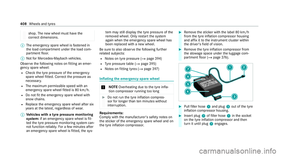
th e tyre inflation compressor. #
Remo vethest icke r with the label 80 km/h
from the tyre inflation compressor housing
and af fix it tothe instrument clus ter within
th e driver's field of vision. #
Remo vethe tyre inflation compressor from
th estow age space under the luggage com‐
partment floor (/ page376). #
Pull filler hose 1and plug 3out of the tyre
inflation compressor housing. #
Insert plug 7offiller hose 1inthe soc ket
on the tyre inflation compressor and then
turn it until plug 7engages. 408
Wheels and tyres
Page 412 of 549
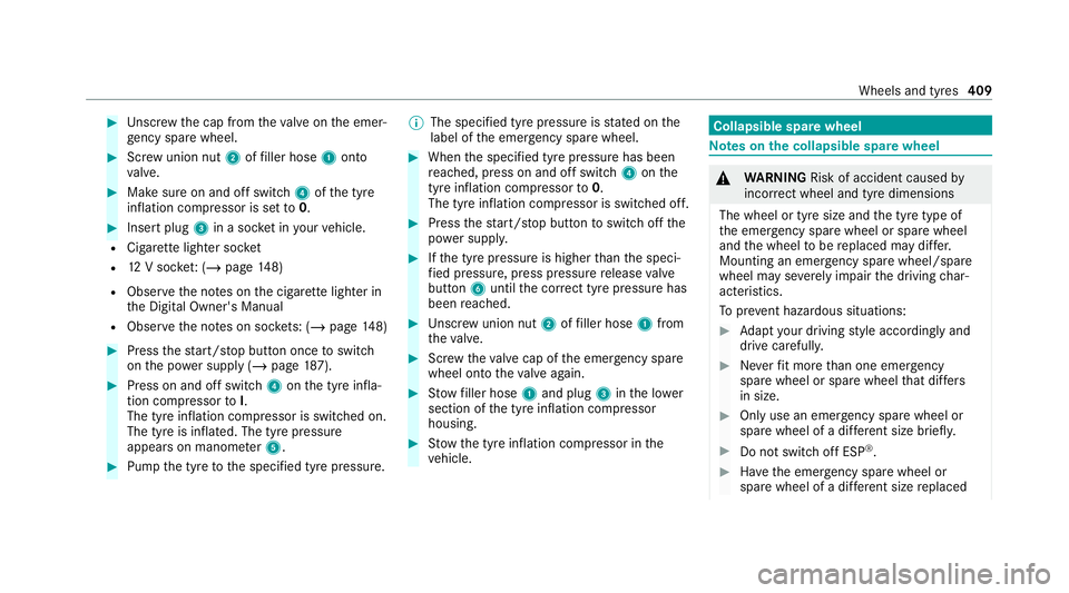
#
Unscr ew the cap from theva lve on the emer‐
ge ncy spa rewheel. #
Screw union nut 2offiller hose 1onto
va lve. #
Make sure on and off switch 4ofthe tyre
inflation compressor is set to0. #
Insert plug 3in a soc ket in your vehicle.
R Cigar ette lighter soc ket
R 12V soc ket: ( / page 148)
R Obse rveth e no tes on the cigar ette lighter in
th e Digital Owner's Manual
R Obser vethe no tes on soc kets: (/ page 148) #
Press thest art/ stop button once toswitch
on the po wer supp ly (/ page187). #
Press on and off switch 4onthe tyre infla‐
tion compressor toI.
The tyre inflation compressor is switched on.
The tyre is inflated. The tyre pressure
appears on manome ter5. #
Pump the tyre tothe specified tyre pressure. %
The specified tyre pressure is stated on the
label of the emer gency spa rewheel. #
When the specified tyre pressure has been
re ached, press on and off swit ch4 onthe
tyre inflation compressor to0.
The tyre inflation compressor is switched off. #
Press thest art/ stop button toswitch off the
po we r supp ly. #
Ifth e tyre pressure is higher than the speci‐
fi ed pressure, press pressure release valve
bu tton 6until the cor rect tyre pressure has
been reached. #
Unscr ew union nut 2offiller hose 1from
th eva lve. #
Screw theva lve cap of the emer gency spa re
wheel onto theva lve again. #
Stow filler hose 1and plug 3inthe lo wer
section of the tyre inflation compressor
housing. #
Stow th e tyre inflation compressor in the
ve hicle. Collapsible spare wheel
Note
s onthe collapsible spa rewheel &
WARNING Risk of accident caused by
incor rect wheel and tyre dimensions
The wheel or tyre size and the tyre type of
th e emer gency spa rewheel or spare wheel
and the wheel tobe replaced may dif fer.
Mounting an emer gency spa rewheel/spare
wheel may se verely impair the driving char‐
acteristics.
To preve nt hazardous situations: #
Adapt your driving style according lyand
drive carefull y. #
Neverfit more than one emer gency
spa rewheel or spare wheel that dif fers
in size. #
Only use an emer gency spa rewheel or
spare wheel of a dif fere nt size brie fly. #
Do not switch off ESP ®
. #
Have the emer gency spa rewheel or
spare wheel of a dif fere nt size replaced Wheels and tyres
409
Page 413 of 549
at
the nearest qualified specialist work‐
shop. The new wheel must ha vethe
cor rect dimensions. The collapsible spa
rewheel is an emer gency
spa rewheel which is only suitable for use for a
limi ted period of time and in a restricted manner
in theeve nt of a flat tyre (e.g. until the nearest
wo rkshop).
The tyre side walls are folded when in transpo rt
mode. Before use, the collapsible spare wheel
has tobe inflated with the accompanying com‐
pressor.
Check the tyre pressure of the collapsible spare
wheel once fitted. Co rrect the pressure as nec‐
essar y.
The maximum permissible speed with a collapsi‐
ble spare wheel fitted is 80 km/h.
Do not fit snow chains with the collapsible spare
wheel.
Re place the collapsible spare wheel af ter six
ye ars at the latest, rega rdless of wear.
% Ve
hicles with a tyre pressure monitoring
sy stem: if a collapsible spare wheel is fitted th
e tyre pressure monitoring sy stem cann ot
function reliably. For a few minutes af ter an
emergency spare wheel is fitted, the sy stem
may still display the tyre pressure of the
re mo ved wheel. Only restart the sy stem
again when the collapsible spare wheel has
been replaced with a new wheel.
Be sure toalso obse rveth efo llowing fur ther
re lated subjects:
R Notes on tyre pressure (/ page 394)
R Tyre pressure table (/ page 395)
Note s onvehicles with a Burmes ter sound
sy stem &
WARNING Risk of inju ryor death due to
an unsecured collapsible spare wheel
If th e collapsible spare wheel is not secured
cor rectl y,it can slip, tip over or be thrown
around.
Ve hicle occupants could be hit byan unse‐
cured collapsible spare wheel and be seri‐
ously injured as a result, particularly when accelerating, braking, abruptly
changing
direction or in theeve nt of an accident. #
Alw aysst ore the collapsible spare
wheel in the emer gency spa rewheel
bag and attach it tothe brac ket in the
load compartment. #
Alw ays ensure that the lashing stra ps
on the emer gency spa rewheel bag are
safely secured on there ar tie-down
ey es on the load compartment floor. Depending on
theve hicle's equipment, the col‐
lapsible spare wheel is located in an emer gency
spa rewheel bag on a brac ket in the load com‐
partment. The collapsible spare wheel in the
emer gency spa rewheel bag and the brac ket are
lashed wi thstra ps and secured using there ar
tie-down eyes on the load compartment floor. Re
moving the collapsible spare wheel Ve
hicles without a Burmes ter sound sy stem
The collapsible spare wheel is located under the
load compartment floor. 41 0
Wheels and tyres
Page 414 of 549
#
Obser vethe information on mounting tyres
(/ page 397). #
Open theta ilgate. #
Open the load compartment floor. #
Remo vethe collapsible spare wheel.
Ve hicles with a Burmes ter sound sy stem
The collapsible spare wheel is secured in the col‐
lapsible spare wheel bag in the load compart‐
ment. #
Obser vethe information on mounting tyres
(/ page 397). #
Open the load compartment. #
Loosen the lashing stra ps. #
Unhook there taining spring hooks of the
lashing stra ps from the brac kets. #
Remo vethe collapsible spare wheel bag
to ge ther with the collapsible spare wheel. #
Open the collapsible spare wheel bag and
re mo vethe collapsible spare wheel. Mercedes‑Maybach
vehicles
Wi thout refrigerator box: the collapsible spare
wheel is located in the collapsible spare wheel
bag on the load compartment floor. #
Obser vethe information on mounting tyres
(/ page 397). #
Open the load compartment. #
Loosen the lashing stra ps. #
Unhook there taining spring hooks of the
lashing stra ps from the brac kets. #
Remo vethe collapsible spare wheel bag
to ge ther with the collapsible spare wheel. #
Open the collapsible spare wheel bag and
re mo vethe collapsible spare wheel.
Wi th refrigerator box: the collapsible spare
wheel is located in the collapsible spare wheel
bag inside the open load compartment floor. #
Obser vethe information on mounting tyres
(/ page 397). #
Open the load compartment. #
Loosen the lashing stra ps. #
Unhook there taining spring hooks of the
lashing stra ps from the brac kets. #
Remo vethe collapsible spare wheel bag
to ge ther with the collapsible spare wheel. #
Open the collapsible spare wheel bag and
re mo vethe collapsible spare wheel. Inflating
the collapsible spa rewheel Re
quirements:
R Mount the collapsible spare wheel as descri‐
bed (/ page 406).
R Remo vethe tyre inflation compressor from
th estow agewell under the boot floor
(/ page 376).
* NO
TEDama getothe collapsible spare
wheel when lo wering theve hicle Lo
we ring theve hicle without pr eviously
inflating the collapsible spare wheel can
damage its rim. Wheels and tyres
411
Page 415 of 549

#
Inflate the collapsible spare wheel using
th e tyre inflation compressor before
lo we ring theve hicle. *
NO
TEOverheating due tothe tyre infla‐
tion compressor running too long #
Do not runth e tyre inflation compres‐
sor for longer than ten minu tes without
inter ruption. #
Pull connec tor4 and the hose out of the
housing. #
Unscr ew the cap from theva lve on the col‐
lapsible spare wheel. #
Screw union nut 1ofthe hose onto the
va lve.
Make sure on and off switch 3ofthe tyre
inflation compressor is set to0. #
Insert plug 4into the cigar ette lighter
soc ket or into a 12V soc ket (/ page 148) in
yo ur vehicle. #
Switch on the po wer supp ly (/ page 187). #
Press On/Off switch 3onthe tyre inflation
compressor toI.
The tyre inflation compressor is switched on.
The tyre is inflated. The tyre pressure is
shown on manome ter2. #
Pump the tyre tothe specified tyre pressure.
% The specified tyre pressure is printed on the
ye llow label of the collapsible spare wheel. #
When the specified tyre pressure has been
re ached, press on and off swit ch3 onthe
tyre inflation compressor to0. #
Ifth e tyre pressure is higher than the speci‐
fi ed pressure, press pressure release valve bu
tton 5until the cor rect tyre pressure has
been reached. 412
Wheels and tyres
Page 430 of 549
Ve
hicle dimensions All models
Ve
hicle lengt h5 207 mm
Ve hicle length, AMG Styling 52 13mm
Ve hicle width including out‐
side mir rors 21
57 mm
Ve hicle width excluding out‐
side mir rors, min. tomax. 19
56 mm -
2030 mm
Maximum vehicle height (AIR‐
MATIC) 18
88 mm
Maximum vehicle height (Off-
ro ad pac kage) 19
28 mm
Minimum vehicle height (high‐
wa y driving le vel) 18
23 mm -
18 38 mm
Wheelbase 3135 mm
Maximum ground clea rance
(AIRMATIC) 259 mm All models
Maximum ground clearance
(Off-road pa
ckage) 289 mm
Minimum ground clearance
(AIRMATIC/Off- road pac kage) 17
4 mm Mercedes‑Maybach
Ve
hicle lengt h5 205 mm
Ve hicle width including out‐
side mir rors 21
57 mm
Ve hicle width excluding out‐
side mir rors 2030 mm
Maximum vehicle height 1888 mm
Minimum vehicle height (high‐
wa y driving le vel) 18
38 mm
Wheelbase 3135 mm
Maximum ground clea rance 210 mm We
ights and loads Please no
tethat forth e specified vehicle data:
R Items of optional equipment increase the
unladen weight and reduce the pa yload.
R Vehicle-specific weight information can be
fo und on theve hicle identification plate
(/ page 415).
Ro of load All models
Maximum
roof load 100kg Ru
nning board All models
Maximum load
200kg Te
ch nical da ta427
Page 468 of 549

Display messages
Possible causes/consequences and M
MSolutions
Active Steering Assist cur-
rently unavailable due to
multiple emergency stops *A
ctive Steering Assist is temp orarily una vailable due tomultiple emergency stops. #
Take ove rth esteering and stop in accordance with the tra ffic conditions. #
Swit chthe ignition off and switch it back on.
Ac tive Steering Assist is available once more.
Beginning emergency stop *Y
our hands are not on thesteering wheel. An emer gency stop is being initiated (/ page248). #
Put your hands back on thesteering wheel.
Yo u can cancel the deceleration at any time byper form ing one of thefo llowing actions:
R Steering
R Braking or accelerating
R Deactivating Active Dis tance Assi stDISTRONIC
Ø *A
ctive Steering Assist has reached the sy stem limits (/ page246).
Yo u ha venot steered independently for a considerable period of time. #
Take ove rth esteering and drive on in accordance with the traf fic conditions.
Active Stop-and-Go Assist
currently unavailable see
Owner's Manual *A
ctive Stop-and-Go Assist is temp orarily una vailable. Active Dis tance Assi stDISTRONIC and Active Steering Assist
are still available.
The ambient conditions are outside the sy stem limits (/ page243).
As soon as the ambient conditions are within the sy stem limits, the sy stem will become available again. #
Drive on. Display messages and
warning/indicator lamps 465