2020 MERCEDES-BENZ AMG GT R-ROADSTER automatic transmission
[x] Cancel search: automatic transmissionPage 133 of 441
Electric pa
rking brake function (releasing
automatically)
The elect ric pa rking brake is released when the
fo llowing conditions are fulfilled:
R The driver's door is closed.
R The engine is running.
R The transmission is in position hork and
yo u depress the accelera tor pedal or you
shift from transmission position jtoh or
k when on le velground withthe driver's
door closed.
R Ifth e transmission is in position k,theta il‐
gate must be closed.
R The seat belt tongue is inser ted into the seat
belt buckle of the driver's seat.
If th e seat belt tongue is not inser ted into the
seat belt buckle of the driver's seat, one of the
fo llowing conditions must be fulfilled:
R You shift from transmission position j.
R You ha veprev iously driven at speeds greater
th an 3 km/h. When
the electric parking brake is released, the
re d! indicator lamp in the instrument clus‐
te r goes out.
Applying/releasing the electric pa rking
brake manually
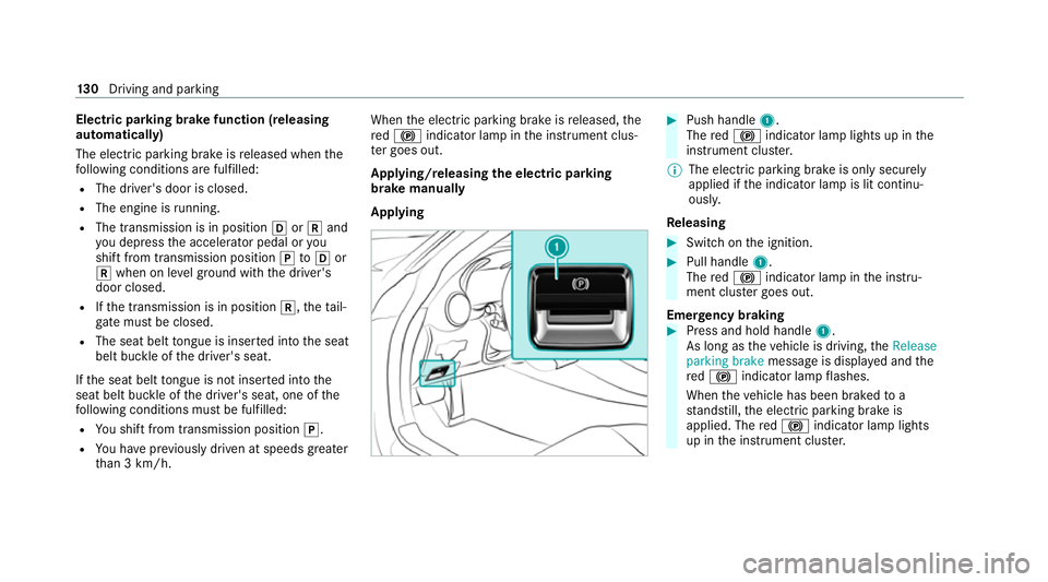
Applying #
Push handle 1.
The red! indicator lamp lights up in the
instrument clus ter.
% The electric parking brake is only securely
applied if the indicator lamp is lit continu‐
ously.
Re leasing #
Swit chon the ignition. #
Pull handle 1.
The red! indicator lamp in the instru‐
ment clus ter goes out.
Emer gency braking #
Press and hold handle 1.
As long as theve hicle is driving, theRelease
parking brake message is displa yed and the
re d! indicator lamp flashes.
When theve hicle has been braked to a
st andstill, the electric parking brake is
applied. The red! indicator lamp lights
up in the instrument clus ter. 13 0
Driving and pa rking
Page 153 of 441
R
The transmission has been shif tedto the
park position j.
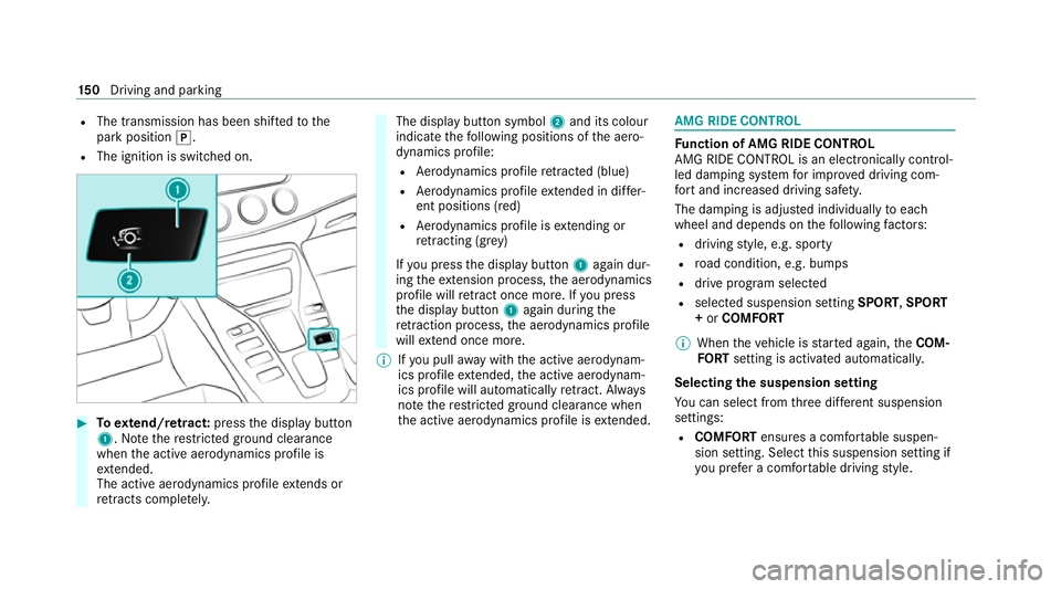
R The ignition is switched on. #
Toextend/r etra ct: press the display button
1. Notethere stricted ground clearance
when the active aerodynamics profile is
ex tended.
The acti veaerodynamics profile extends or
re tracts compl etely. The display button symbol
2and its colour
indicate thefo llowing positions of the aero‐
dynamics profile:
R Aerodynamics profile retracted (blue)
R Aerodynamics profile extended in di ffer‐
ent positions (red)
R Aerodynamics profile is extending or
re tracting (gr ey)
If yo u press the display button 1again dur‐
ing theex tension process, the aerodynamics
profile will retract once more. If you press
th e display button 1again during the
re traction process, the aerodynamics profile
will extend once more.
% Ifyo u pull away with the active aerodynam‐
ics profile extended, the active aerodynam‐
ics profile will automatically retract. Alw ays
no te there stricted ground clearance when
th e active aerodynamics profile is extended. AMG RIDE CONTROL
Fu
nction of AMG RIDE CONTROL
AMG RIDE CONTROL is an electronically control‐
led damping sy stem for impr oved driving com‐
fo rt and inc reased driving saf ety.
The damping is adjus ted individually toeach
wheel and depends on thefo llowing factors:
R driving style, e.g. sporty
R road condition, e.g. bumps
R drive program selec ted
R selected suspension setting SPORT,SPORT
+ or COMFORT
% When theve hicle is star ted again, theCOM‐
FO RT setting is activated automatically.
Selecting the suspension setting
Yo u can select from thre e dif fere nt suspension
settings:
R COMFORT ensures a comfor table suspen‐
sion setting. Select this suspension setting if
yo u prefer a comfor table driving style. 15 0
Driving and pa rking
Page 238 of 441
Setting
there ception and transmission vol‐
ume
Re quirements:
R The mobile phone is authorised
(/ page 232).
Multimedia sy stem:
4 Telephone 5
Z Options
5 Telephone
This function ensures optimal language qualit y. #
Select Reception volume orTransmission
volume. #
Set thevo lume.
Fu rther information on there commended recep‐
tion and transmission volume: https://
www.me rcedes-benz-mobile.com/
Ad justing the call and ringtone volume
Multimedia sy stem:
4 System 5
õ Audio 5
Telephone #
Select Speech volume orRingtone volume . #
Set thevo lume. St
arting/ stopping mobile phone voice recog‐
nition
Re quirements:
R The mobile phone is connecte dto the multi‐
media sy stem (/ page 232).
St arting mobile phone voice recognition #
Press and hold theó button on the multi‐
function steering wheel for more than one
second.
Yo u can use mobile phone voice recognition.
St opping mobile phone voice recognition #
Press the8 or~ button on the multi‐
function steering wheel. Business
telephony Overview of business
telephony operating
modes
Business telephony of fers youth efo llowing
operating modes:
R Using SIM card (/ page 236)
R Using SIM card in combination with a spe‐
cific mobile phone This operating mode is mainly intended
for
th ose using multiple SIM cards. As soon as
th e mobile phone associated with the SIM
card is connected with the multimedia sys‐
te m in theve hicle, the SIM card is automati‐
cally activated for business telephon y.The
association of the SIM card with the set
mobile phone pr events automatic activation
of business telephony via the SIM card if the
ve hicle is bor rowedby ot her persons, for
ex ample (/ page 236).
R Using a mobile phone with Blue tooth®
profile
SA P (SIM Access Profile) (/ page 236) Multimedia sy
stem 235
Page 316 of 441
R
When connecting and disconnecting the bat‐
te ry, alw ays obser vethe sequence of battery
te rm inals desc ribed.
Obser vethe additional following points when
ch arging the battery:
R Only use battery charge rs tested and
appr ovedfo r Mercedes-Benz.
R Read the battery charge r's operating instruc‐
tions before charging the batter y.
Obser vethe additional following points during
st arting assis tance:
R Starting assis tance may only be pr ovided
using vehicles, batteries or other jump start
devices with a nominal voltage of 12V.
R The vehicles must not touch.
R Take care toconnect only battery term inals
of identical polarity.
R Obser vethe sequence described for con‐
necting and disconnecting the jumper
cables. R
Vehicles with a petrol engine: jump-start
th eve hicle only when the engine and exhaust
sy stem are cold. St
arting assi stance and charging the 12 V
battery Re
quirements:
R The vehicle is secured with the electric park‐
ing brake.
R Vehicles with automatic transmission: the
transmission is in position j.
R The ignition and all electrical consumers are
switched off.
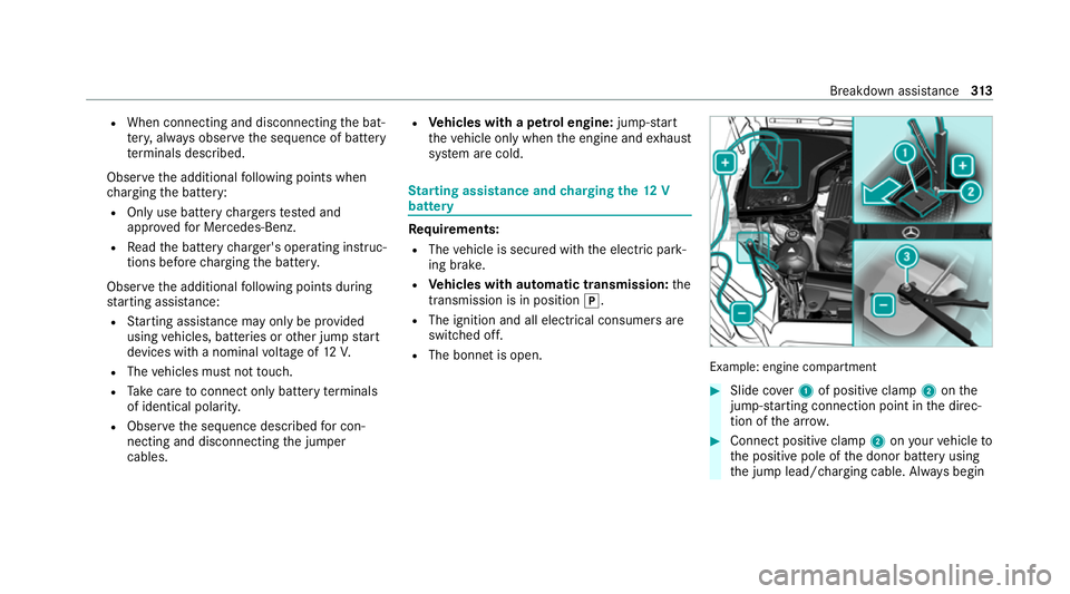
R The bonnet is open. Example: engine compartment
#
Slide co ver1 of positive clamp 2onthe
jump-s tarting connection point in the direc‐
tion of the ar row. #
Connect positive clamp 2onyour vehicle to
th e positive pole of the donor battery using
th e jump lead/charging cable. Alw ays begin Breakdown assis
tance 313
Page 319 of 441
R
vehicles with automatic transmission: the
automatic transmission cannot be shif tedto
position iorj
% Vehicles with automatic transmission: if
th e automatic transmission cann otbe shif‐
te dto position i, orthe multifunction dis‐
play in the instrument clus ter does not show
anything, ha vetheve hicle transpor tedaw ay
( / page 317). Atowing vehicle with lifting
equipment is requiredforve hicle transpor ta‐
tion.
* NO
TEDama gedue to to wing away at
exc essively high speeds or over long dis‐
ta nces The driv
etra in could be damaged when tow‐
ing at excessively high speeds or over long
dis tances. #
Atowing speed of 50 km/h must not
be exc eeded. #
Atowing dis tance of 50 km must not be
exc eeded. &
WARNING Risk of accident when towing
a ve hicle which is too heavy
If ano ther vehicle is tow- star ted or towed
aw ay, its weight must not exceed the permis‐
sible gross mass of your ow nve hicle, other‐
wise thefo llowing could occur:
R theto wing eye may become de tach ed.
R theve hicle/trailer combination may
swer veoreve nov erturn. #
If ano ther vehicle is tow- star ted or
to we daw ay, its weight must not exceed
th e permissible gross mass of your own
ve hicle. If a
vehicle must be tow- star ted or towe daw ay,
its permissible gross weight must not exceed the
permissible gross weight of theto wing vehicle. #
Information on the permissible gross mass of
th eve hicle can be found on theve hicle iden‐
tification plate (/ page 338). #
Vehicles with automatic transmission: do
not open the driver's door or front passenger door,
otherwise the automatic transmission
automatically shifts toposition j. #
Fittheto wing eye (/ page318). #
Fasten theto w bar.
* NO
TEDama gedue toincor rect connec‐
tion of theto w bar #
Onlyconnect theto w rope or tow bar to
th eto wing eyes. #
Deactivate the automatic locking mechanism
(/ page 65). #
Do not activate the HOLD function. #
Deactivate tow- aw ay protection
(/ page 73). #
Deactivate Active Brake Assi st
( / page 138). #
Vehicles with automatic transmission:
shift the automatic transmission toposition
i. #
Release the electric parking brake. 316
Breakdown assis tance
Page 320 of 441
&
WARNING Risk of accident due tolimi‐
te d saf ety-re lated functions during the
to wing process
Saf ety-re lated functions are limited or no lon‐
ge rav ailable in thefo llowing situations:
R the ignition is switched off.
R the brake sy stem or po werst eering sys‐
te m is malfunctioning.
R the energy supply or the on-board electri‐
cal sy stem is malfunctioning.
When your vehicle is then towe daw ay, signif‐
icantly more ef fort may be requ ired tosteer
and brake than is norm allyrequ ired. #
Use a tow bar. #
Make sure that thesteering wheel can
mo vefreely before towing theve hicle
aw ay. *
NO
TEDama gedue toexcessive tracti ve
po wer If
yo u pull away sharpl y,the tractive po wer
may be too high and theve hicles could be
damaged. #
Pull away slowly and smoo thly. Loading the
vehicle for transport #
Obser vethe no tes on towing away
( / page 315). #
Con nect theto w bar totheto wing eye in
order toload theve hicle. #
Shift the automatic transmission toposition
i.
% The automatic transmission may be loc ked
in position jintheeve nt of damage tothe
electrics. Toshift toi , pr ovide the on-
board electrical sy stem with po wer
( / page 313). #
Load theve hicle onto the transpor ter. #
Shift the automatic transmission toposition
j. #
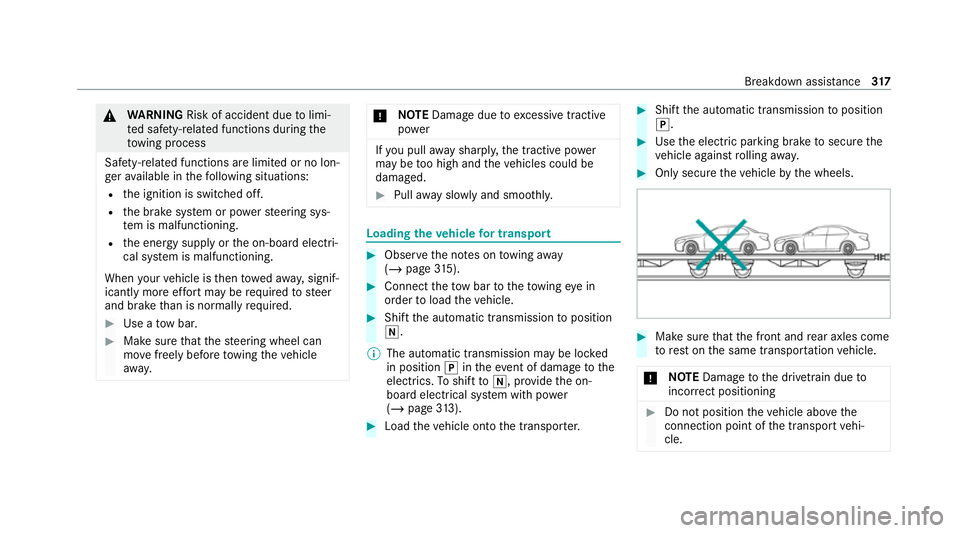
Use the electric parking brake tosecure the
ve hicle against rolling away. #
Only secure theve hicle bythe wheels. #
Make sure that the front and rear axles come
to rest on the same transpor tation vehicle.
* NO
TEDama getothe driv etra in due to
incor rect positioning #
Do not position theve hicle abo vethe
connection point of the transport vehi‐
cle. Breakdown assis
tance 317
Page 321 of 441
To
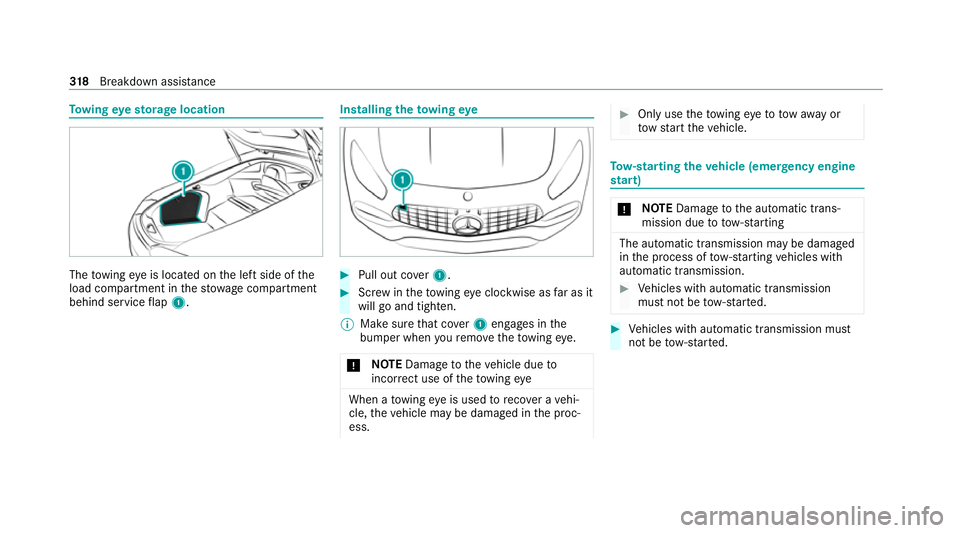
wing eyesto rage location The
towing eye is located on the left side of the
load compartment in thestow age compartment
behind service flap 1. Installing
theto wing eye #
Pull out co ver1. #
Screw intheto wing eyeclockwise as far as it
will go and tighten.
% Make sure that co ver1 engages in the
bumper when youre mo vetheto wing eye.
* NO
TEDama getotheve hicle due to
incor rect use of theto wing eye When a
towing eye is used toreco ver a vehi‐
cle, theve hicle may be damaged in the proc‐
ess. #
Only use theto wing eyeto to waw ay or
to w start theve hicle. To
w- starting theve hicle (eme rgency engine
st art) *
NO
TEDama getothe automatic trans‐
mission due to tow-starting The automatic transmission may be damaged
in
the process of tow- starting vehicles with
automatic transmission. #
Vehicles with automatic transmission
must not be tow- star ted. #
Vehicles with automatic transmission must
not be tow- star ted. 318
Breakdown assis tance
Page 367 of 441
Display messages
Possible causes/consequences and M MSolutions
Transmission Malfunction
Stop *
The transmission is malfunctioning. The transmission shifts toneutral iautomatically. #
Stop theve hicle immediately in accordance with the traf fic conditions. #
Depress the brake pedal. #
Enga gepark position j. #
Consult a qualified specialist workshop.
Stop vehicle Leave engine
running Wait Transmission
cooling *T
he transmission is overheating. Pulling away may be temp orarily impaired or not possible. #
Stop theve hicle immediately in accordance with the traf fic conditions. Do not continue driving. #
Lea vethe engine running. #
Wait until the display message disappears before pulling away.
d Transmission oil cooling
Malfunction *T
he transmission's coolant pump is faulty. The transmission may overheat. #
Select thePerformance menu inthe on-board computer and check the transmission oil temp erature . #
Avoid a high load with a dynamic driving style. #
If transmission oil temp eratures are below 120 °C, drive on tothe nearest qualified specialist workshop. 364
Display messages and warning/indicator lamps