2020 MASERATI GRANTURISMO light
[x] Cancel search: lightPage 99 of 286

must pass as close as possible to the
side walls of the containment
compartment, avoiding the hooking
area of the handle.
The AUX auxiliary port features:
• typical port impedance between
AUX-IN and AUX_REF: 13 Kohm;
• max. applicable voltage: 0.75 Vrms at
1 kHz;
• port compatible only with 3.5 mm
jack connectors (not included).
Any player with these characteristics
and analog audio output (headset
output type) can be served by the
MTC+ System. The system can
recognize the connection to a player
outlet autonomously, by enabling
access to the audio functions
connected to this source.
This
USB port can be used for
data exchange and charge of the
connected source (refer to the MTC+
guide for further details).
Through this USB input is possible to
recharge the connected device for
about an hour from when the key in
the ignition switch is turned inSTOP
(OFF)position (“Active Charging”
feature). When this feature is enabled,
the USB port will be backlit.
In this compartment there is also an
SD memory card input. Once insertedinto the slot, to extract it press lightly
on the card.
Other two USB ports are present for
rear seat passengers, on the rear part
of the central console.
To access the USB port, open the
outside cover. These USB ports allow
charging the connected source.
When you turn the key in the ignition
switch inSTOP (OFF)position, these
USB ports remain active for 10 minutes
to allow the charging of connected
devices.
iPod®Connection
An iPod®can be connected to the
system via USB and AUX ports by
means of a special cable (optional).
The MTC+ will then control the
following functions: play, pause, fast
forward, rewind, next track, previous
track, random or repeat mode,selection and navigation of
playlist/genre/singer/album/Podcast.
CAUTION!
Do not leave your USB device, iPod®
or an external audio source in the
vehicle for extended period of time:
extreme temperatures and humidity
can occur in the vehicle.
NOTE:
Visitwww.maserati.comor an
Authorized Maserati Dealerfor a list
of iPod
®devices compatible with the
MTC+ and their level of compatibility.
Sun Visors
Sun visors can be folded to the front
and to the side of the vehicle. To move
the visor laterally, lower and release it
from its catch as indicated.
Understanding the Vehicle
3
95
Page 100 of 286
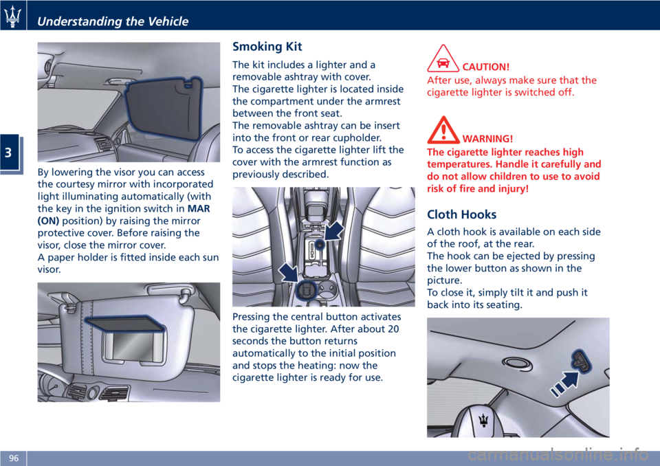
By lowering the visor you can access
the courtesy mirror with incorporated
light illuminating automatically (with
the key in the ignition switch inMAR
(ON)position) by raising the mirror
protective cover. Before raising the
visor, close the mirror cover.
A paper holder is fitted inside each sun
visor.
Smoking Kit
The kit includes a lighter and a
removable ashtray with cover.
The cigarette lighter is located inside
the compartment under the armrest
between the front seat.
The removable ashtray can be insert
into the front or rear cupholder.
To access the cigarette lighter lift the
cover with the armrest function as
previously described.
Pressing the central button activates
the cigarette lighter. After about 20
seconds the button returns
automatically to the initial position
and stops the heating: now the
cigarette lighter is ready for use.CAUTION!
After use, always make sure that the
cigarette lighter is switched off.
WARNING!
The cigarette lighter reaches high
temperatures. Handle it carefully and
do not allow children to use to avoid
risk of fire and injury!
Cloth Hooks
A cloth hook is available on each side
of the roof, at the rear.
The hook can be ejected by pressing
the lower button as shown in the
picture.
To close it, simply tilt it and push it
back into its seating.
Understanding the Vehicle
3
96
Page 102 of 286
The trunk is the most suitable place to
load bulky and heavy objects onboard
the vehicle.
To load your vehicle properly, store
heavier items below and be sure you
distribute their weight as evenly as
possible.
Stow all loose items securely before
start driving as they could move during
the trip.HomeLink®(for
versions/markets, where
provided)
HomeLink®replaces up to three
hand-held transmitters operating the
automatic devices that open garage
doors and gates, enable/disable the
lighting or security systems. The
HomeLink
®unit is powered by your
vehicle's 12 Volt battery. The
HomeLink
®buttons that are located in
the control panel behind the driver's
side sun visor designate the three
different HomeLink
®channels.
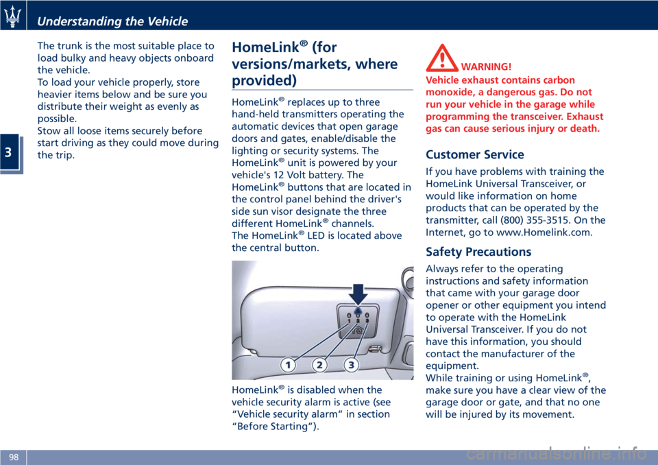
The HomeLink®LED is located above
the central button.
HomeLink
®is disabled when the
vehicle security alarm is active (see
“Vehicle security alarm” in section
“Before Starting”).
WARNING!
Vehicle exhaust contains carbon
monoxide, a dangerous gas. Do not
run your vehicle in the garage while
programming the transceiver. Exhaust
gas can cause serious injury or death.
Customer Service
If you have problems with training the
HomeLink Universal Transceiver, or
would like information on home
products that can be operated by the
transmitter, call (800) 355-3515. On the
Internet, go to www.Homelink.com.
Safety Precautions
Always refer to the operating
instructions and safety information
that came with your garage door
opener or other equipment you intend
to operate with the HomeLink
Universal Transceiver. If you do not
have this information, you should
contact the manufacturer of the
equipment.
While training or using HomeLink
®,
make sure you have a clear view of the
garage door or gate, and that no one
will be injured by its movement.
Understanding the Vehicle
3
98
Page 107 of 286
Sport Skyhook Suspension
(for versions/markets,
where provided)
The electronic system controlling the
vehicle suspension uses the
sophisticated on board sensors and is
aimed at optimizing vehicle
performance.
The system is capable of constantly
monitoring suspension damping by
means of the actuator fitted on each
shock absorber (Skyhook type). This
way, the shock absorber setting is
suited to the road surface conditions
and vehicle dynamics, thus improving
passenger comfort and road-holding.
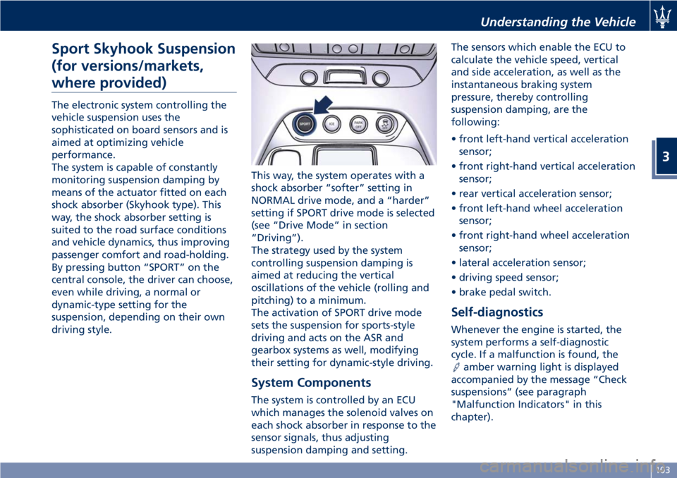
By pressing button “SPORT” on the
central console, the driver can choose,
even while driving, a normal or
dynamic-type setting for the
suspension, depending on their own
driving style.This way, the system operates with a
shock absorber “softer” setting in
NORMAL drive mode, and a “harder”
setting if SPORT drive mode is selected
(see “Drive Mode” in section
“Driving”).
The strategy used by the system
controlling suspension damping is
aimed at reducing the vertical
oscillations of the vehicle (rolling and
pitching) to a minimum.
The activation of SPORT drive mode
sets the suspension for sports-style
driving and acts on the ASR and
gearbox systems as well, modifying
their setting for dynamic-style driving.
System Components
The system is controlled by an ECU
which manages the solenoid valves on
each shock absorber in response to the
sensor signals, thus adjusting
suspension damping and setting.The sensors which enable the ECU to
calculate the vehicle speed, vertical
and side acceleration, as well as the
instantaneous braking system
pressure, thereby controlling
suspension damping, are the
following:
• front left-hand vertical acceleration
sensor;
• front right-hand vertical acceleration
sensor;
• rear vertical acceleration sensor;
• front left-hand wheel acceleration
sensor;
• front right-hand wheel acceleration
sensor;
• lateral acceleration sensor;
• driving speed sensor;
• brake pedal switch.
Self-diagnostics
Whenever the engine is started, the
system performs a self-diagnostic
cycle. If a malfunction is found, the
amber warning light is displayed
accompanied by the message “Check
suspensions” (see paragraph
"Malfunction Indicators" in this
chapter).
Understanding the Vehicle
3
103
Page 108 of 286
Calibration Selection
The driver can select, in relation to
road surface conditions, vehicle speed,
driving style and comfort, one of the
two calibration levels provided by the
system: normal or sports-style.
•Normal calibration, active when
SPORT drive mode is disabled
("SPORT" button not pressed), favors
comfort and higher driving stability
with low and average grip
conditions.
•Sport-style calibration, active when
SPORT drive mode is enabled
("SPORT" button pressed) , favors
wheel drive and permits a
dynamic-style driving with optimal
road holding.
Whenever the engine is started, the
system automatically activates
NORMAL drive mode, even if SPORT
drive mode was selected before the
engine was last turned off.
The sport-style calibration can be
selected only with the key in the
ignition switch inMAR (ON)position
and it is enabled by pressing button
"SPORT", even while driving.
When SPORT drive mode is activated,
the word “SPORT” on the instrument
cluster display and the LED on the
button illuminate.WARNING!
SPORT drive mode should not be
activated if the road surface is rough
or slippery.
The electronic suspension control
system works in combination with the
ESC system.
When the suspension is set to normal
calibration, stability is increased under
medium and low grip conditions, while
when it is set to sport-style calibration,
the ESC system optimizes a sportier
driving.
WARNING!
In low- and medium-grip conditions
(e.g., rain, snow, ice, sand, etc.) it is
advisable not to use SPORT drive
mode, even with the ESC system
enabled.
Malfunction Indicators
If one or more electric components in
the system prove to be malfunctioning
while driving, the ECU illuminates the
amber warning light accompanied
by the message “Check suspensions”
on the display. In addition, the ECU
calibrates the shock absorbers to apreset value, thus ensuring a safe
vehicle set up.
Should the malfunction involve one
shock absorber only, this will no longer
be controlled by the ECU and will
therefore remain set as it was when
the fault occurred. It is therefore
possible for one of the four shock
absorbers to work with a fixed
calibration, different from that of the
other ones.
In any case, safe and secure vehicle
driving is always ensured at low
speeds.
CAUTION!
In the event of a malfunction in the
suspension control electronic system,
which will be indicated by the
illumination of the amber warning
light on the display while driving, keep
a moderate speed and have the vehicle
checked as soon as possible by an
Authorized Maserati Dealer.
If a malfunction occurs while driving,
and this is signaled by the illumination
of the
amber warning light on the
display, it is advisable to stop the
vehicle as soon as possible, turn the
key in the ignition switch toSTOP
(OFF)position and then restart the
engine.
Understanding the Vehicle
3
104
Page 109 of 286
If the malfunction is no longer present
and the
amber warning light on the
display does not illuminate again, the
electronic suspension system will
resume normal operation. On the
other hand, if the problem persists,
the
amber warning light on the
instrument cluster display will turn on
again.
In both cases, the system must be
checked by theAuthorized Maserati
Dealer.
The fault found is memorized by the
ECU and can be diagnosed at an
Authorized Maserati Dealereven if it
has disappeared spontaneously.
Understanding the Vehicle
3
105
Page 112 of 286

Instrument Cluster
The instrument cluster is divided into
three main areas displaying
information, signs and text and/or icon
messages.
AFuel level gage with low fuel
indicator and analog
speedometer showing the
vehicle speed.
BAnalog tachometer and coolant
thermometer with high
temperature warning light.
CTFT display. In addition to other
information, in this area the
odometer display shows the
total distance covered by the
vehicle.
Speedometer and tachometer display
the main warning lights (see “Warning
and Indicator Lights on Analog
Instruments” in this chapter). The
other warning and indicator lights are
displayed on the TFT display together
with mode and drive function
indicators (see “TFT Display:
Warning/Indicator Lights" in this
chapter).
NOTE:
The image shows the instrument
cluster after the initial check cycle.
Sport Version
MC Version
Dashboard Instruments and Controls
4
108
Page 113 of 286

Warning and Indicator Lights
on Analog Instruments
Low Fuel Indicator on Fuel Gage
The illumination of the red indicator
inside the gage indicates that there
are approx. 4.7 Gallons (18 liters) of
fuel in the tank.
If the pointer positions on "0"
(beginning of scale) and the fuel
reserve indicator flashes, it means that
there is a system malfunction.
In this case, contact anAuthorized
Maserati Dealerto have the system
checked.
Telltales on Speedometer
Following telltales are displayed on
the fuel level gage and speedometer,
and related messages are visible for 10
seconds on the central sector of the
display, unless otherwise indicated.The telltales indicated with (*) are also
displayed on the TFT display (see “TFT
Display” paragraph in this chapter).
Charging System Warning Light
This warning light shows the
status of the electrical
charging system. If the light
stays on or comes on while
driving, turn off some of the vehicle's
non-essential electrical devices or
increase engine speed (if at idle). If
the charging system warning light
remains on, it means that the vehicle
is experiencing a problem with the
charging system. Require IMMEDIATE
service at anAuthorized Maserati
Dealer.
If jump starting is required, refer to
“Jump Start Procedures” in section “In
an Emergency”.Malfunction Indicator Light (*)
The Malfunction Indicator
Light (MIL) is part of an
onboard diagnostic system
that monitors engine and
automatic transmission control
systems.
Under normal conditions, this
indicator light should switch on when
the key in the ignition switch is in
MAR (ON)position and switch off
soon after the engine is started.
This is a sign of the indicator light
working properly. If the indicator
remains lighted up or switches on
while driving, there is a failure in the
fuel supply/ignition and emission
control systems.
The failure could cause high exhaust
emissions, loss of performance, poor
vehicle handling and high
consumption levels.
Under these conditions you can
proceed slowly without forcing the
engine or driving at high speeds.
The indicator light will switch off if
the problem is solved.
The error will be registered by the
system in any case.
Dashboard Instruments and Controls
4
109