2020 MASERATI GRANTURISMO trunk
[x] Cancel search: trunkPage 209 of 286
Operating, servicing and maintaining
a passenger vehicle or off-road vehicle
can expose you to chemicals including
such as, engine exhaust, carbon
monoxide, phthalates and lead, that
which are know to the State of
California to cause cancer and birth
defects or other reproductive harm. To
minimize exposure, avoid breathing
exhaust, do not idle the engine except
as necessary, service your vehicle in a
well-ventilated area and wear gloves
or wash your hands frequently when
servicing your vehicle.
NOTE:
For the tire repair procedures with tire
repair kit see instructions included in
the kit.
This kit will provide a temporary tire
seal, allowing you to drive your
vehicle up to 6 miles (10 km) with a
maximum speed of 50 mph (80 km/h).
CAUTION!
• Intruding objects (e.g., screws or
nails) should not be removed from
the tire, which could compromise
the repair with the tire repair kit.
• Do not use the tire repair kit if the
tire shows lateral damages and/orthe rim is damaged by driving with
flat tire.
• Tire repair kit can be used in outside
temperatures down to
approximately -4°F (-20°C).
• Replace the tire repair kit sealant gas
cylinder prior to the expiration date
(printed on the gas cylinder label) to
assure optimum operation of the
system.
NOTE:
•The compressor power plug can be
inserted either in the 12 V power
outlet housed in the trunk or inside
the passenger compartment (see
“Interior Features” in section
“Understanding the Vehicle”).
•When having the tire serviced,
advise theAuthorized Maserati
Dealeror service center that the tire
has been sealed using the tire repair
kit.
Using the Compact Spare
Wheel (for versions/markets
where provided)
Upon request, the vehicle may come
equipped with a compact spare wheel
(emergency wheel), jack and tools for
replacing a wheel.The compact spare wheel is stored in
the trunk and is supplied deflated in
order to limit the amount of space
occupied. An electric compressor is
also provided for inflating. In the
event of a tire puncture, proceed as
follows.
• Stop the vehicle in a place that does
not constitute a danger to traffic
and where the wheel can be
changed safely. The vehicle must be
level and on firm ground.
• Select the P (Park) mode and then
engage manually the electric
parking brake and turn the key in
the ignition switch toSTOP (OFF)
position.
• If necessary, turn the hazard warning
flashers on and place the warning
triangle at the required distance.
WARNING!
•The jack should be used on level
firm ground wherever possible.
•It is recommended that the wheels
of the vehicle be chocked, and that
no person should remain in a vehicle
that is being jacked.
•If the vehicle has been stopped on a
(Continued)
In an Emergency
6
205
Page 210 of 286
(Continued)
slope or an uneven surface, place
chocks or other suitable items in
front of or behind the wheels to
stop the vehicle from moving.
•Never start or run the engine with
the vehicle on a jack.
•No person should place any portion
of their body under a vehicle that is
supported by a jack.
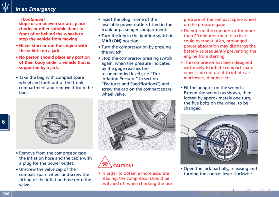
• Take the bag with compact spare
wheel and tools out of the trunk
compartment and remove it from the
bag.
• Remove from the compressor case
the inflation hose and the cable with
a plug for the power outlet.
• Unscrew the valve cap of the
compact spare wheel and screw the
fitting of the inflation hose onto the
valve.• Insert the plug in one of the
available power outlets fitted in the
trunk or passenger compartment.
• Turn the key in the ignition switch in
MAR (ON)position.
• Turn the compressor on by pressing
the switch.
• Stop the compressor pressing switch
again, when the pressure indicated
by the gage reaches the
recommended level (see “Tire
Inflation Pressure” in section
“Features and Specifications”) and
screw the cap on the compact spare
wheel valve.
CAUTION!
• In order to obtain a more accurate
reading, the compressor should be
switched off when checking the tirepressure of the compact spare wheel
on the pressure gage.
• Do not run the compressor for more
than 20 minutes: there is a risk it
could overheat. Also, prolonged
power absorption may discharge the
battery, subsequently preventing the
engine from starting.
• The compressor has been designed
exclusively to inflate compact spare
wheels; do not use it to inflate air
mattresses, dinghies etc.
• Fit the adapter on the wrench.
Extend the wrench as shown, then
loosen by approximately one turn,
the five bolts on the wheel to be
changed.
• Open the jack partially, releasing and
turning the control lever clockwise.
In an Emergency
6
206
Page 213 of 286
7 lbf·ft / 98 ± 10 Nm). This is
equivalent to a load of
approximately 44 lb (20 kg) being
placed on the handle of the wrench
supplied when extended for use.
•After refitting the standard wheel,
check the tire pressure.
Once finished:
• completely deflate the compact
spare wheel by pressing on the valve
with the overhang of the valve cap;
• wrap the power cable and the
inflation hose inside the compressor
case;
• place the compressor, the jack, the
wrench and the adapter in the
container inside the compact spare
wheel;
• put the compact spare wheel in its
bag and put it back in the trunk
compartment.
Emergency Release of the
Parking Brake
In the event the electric parking brake
locks due to a total system failure (see
“Parking Brake” in section “Driving”),
it is not possible to move the vehicle,
since the thrust action of the brake
shoes will lock the rear wheels.
For moving the vehicle it is therefore
necessary to manually act on the
electric actuator to release the
pressure of the brake shoes on the
rear wheels by performing the
following operation.
CAUTION!
If the parking brake has been
activated in manual or automatic
mode and it is not possible to release
it by operating on the lever of the
central console, do not move the
vehicle since rear brake calipers might
be damaged. If you are not able to
perform the following operation, to
move the vehicle, load it on a rescue
vehicle, avoiding to move it. For more
information on vehicle towing, see
"Towing a Disabled Vehicle" chapter
in this section.
Manual Release Procedure
To manually release the parking brake,
you need to use the special tool
provided in the tool kit (see "Tool Kit"
in this section).
Proceed as follows:
• remove any luggage and/or the bag
containing the compact spare wheel
(if equipped) from the trunk
compartment;
• remove the floor panel from the
trunk compartment;
• remove the inside covering panel
from the battery compartment;
• remove the container in the rear
part of the trunk compartment
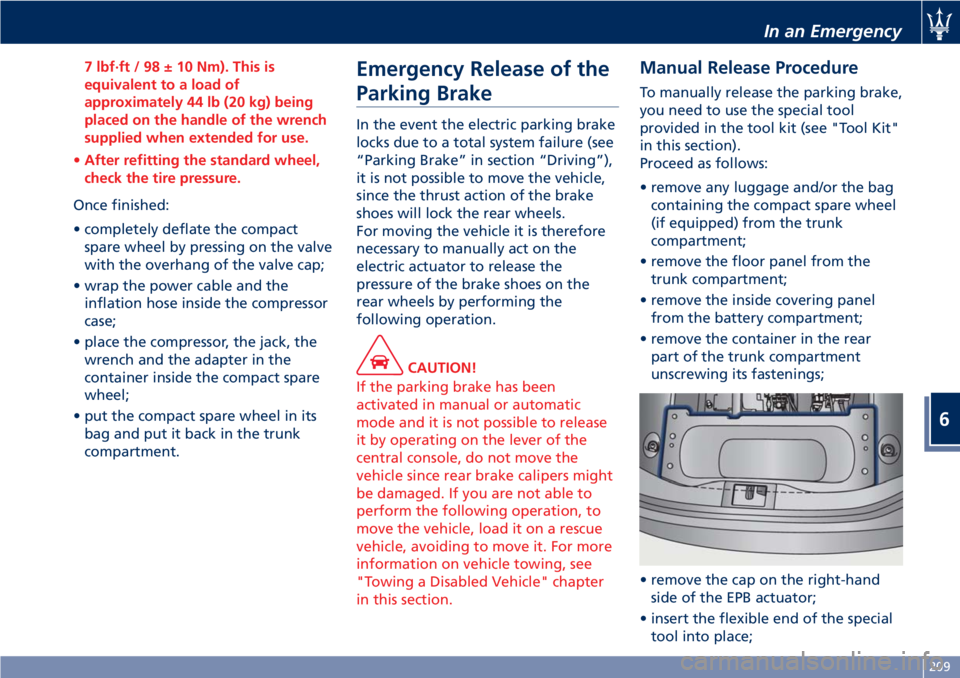
unscrewing its fastenings;
• remove the cap on the right-hand
side of the EPB actuator;
• insert the flexible end of the special
tool into place;
In an Emergency
6
209
Page 219 of 286

open flames or cigarettes that could
generate sparks.
NOTE:
If you need to disconnect the battery
from the vehicle electrical system, see
“Maintenance - Free Battery” in
section “Maintenance and Care”).
Access the Battery
The battery is stored in the trunk.
• Open the trunk lid (see “Open and
Close the Trunk Lid” in section
“Before Starting”).
• Remove any luggage from the trunk
compartment.
• Remove the floor panel from the
trunk compartment.
• Remove the inside covering panel
from the battery compartment.Remove the cover from the right side
of the battery which protects the
positive pole.
Jump-Start Procedure
WARNING!
•The battery is secured to the vehicle
with a metal clamp (indicated in the
picture), so be extremely careful not
to let the clips on the end of the
cables come into contact with it.
•Remove any metal jewelry such as
watch bands or bracelets that might
make an inadvertent electrical
contact. You could be seriously
injured.
•Do not allow the vehicles involved
in the jump-starting operation to
touch each other as this could
establish a ground connection and
cause personal injury.
• Turn off the heater, radio, and all
unnecessary electrical accessories.
• Set the parking brake, shift the
automatic transmission into P (Park)
and turn the key in the ignition
switch toSTOP (OFF)position.
• If using another vehicle to jump start
the battery, park the vehicle withinthe jumper cables reach and set the
parking brake and make sure the
ignition is off.
• Connect one terminal clamp of the
positive jumper cable to the positive
(+) pole of the discharged battery.
• Connect the opposite terminal clamp
of the positive (+) jumper cable to
the positive (+) pole of the booster
battery.
• Connect one terminal clamp of the
negative jumper cable to the
negative (–) pole of the booster
battery.
• Connect the opposite terminal clamp
of the negative (–) jumper cable to
the negative (–) pole of the
discharged battery.
• Start the engine in the vehicle that
has the booster battery, let the
engine idle a few minutes, and then
start the engine in the vehicle with
In an Emergency
6
215
Page 222 of 286
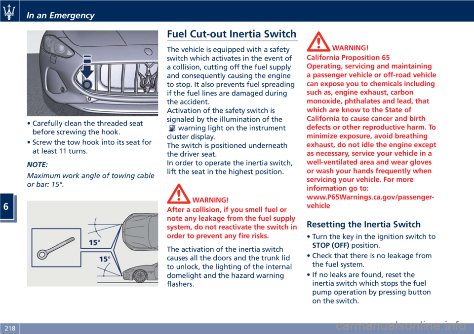
• Carefully clean the threaded seat
before screwing the hook.
• Screw the tow hook into its seat for
at least 11 turns.
NOTE:
Maximum work angle of towing cable
or bar: 15°.
Fuel Cut-out Inertia Switch
The vehicle is equipped with a safety
switch which activates in the event of
a collision, cutting off the fuel supply
and consequently causing the engine
to stop. It also prevents fuel spreading
if the fuel lines are damaged during
the accident.
Activation of the safety switch is
signaled by the illumination of the
warning light on the instrument
cluster display.
The switch is positioned underneath
the driver seat.
In order to operate the inertia switch,
lift the seat in the highest position.
WARNING!
After a collision, if you smell fuel or
note any leakage from the fuel supply
system, do not reactivate the switch in
order to prevent any fire risks.
The activation of the inertia switch
causes all the doors and the trunk lid
to unlock, the lighting of the internal
domelight and the hazard warning
flashers.
WARNING!
California Proposition 65
Operating, servicing and maintaining
a passenger vehicle or off-road vehicle
can expose you to chemicals including
such as, engine exhaust, carbon
monoxide, phthalates and lead, that
which are know to the State of
California to cause cancer and birth
defects or other reproductive harm. To
minimize exposure, avoid breathing
exhaust, do not idle the engine except
as necessary, service your vehicle in a
well-ventilated area and wear gloves
or wash your hands frequently when
servicing your vehicle. For more
information go to:
www.P65Warnings.ca.gov/passenger-
vehicle
Resetting the Inertia Switch
• Turn the key in the ignition switch to
STOP (OFF)position.
• Check that there is no leakage from
the fuel system.
• If no leaks are found, reset the
inertia switch which stops the fuel
pump operation by pressing button
on the switch.
In an Emergency
6
218
Page 229 of 286

Service coupons 1° 2° 3° 4° 5° 6° 7° 8° 9° 10° 11° 12°
Main operations Maintenance schedules: every 12500 mi (20000 km) or 2 years
Air injection system: connections and pipes
valvesIIIIIIIIIIII
Blow-by systemIII II
Fuel emission control system: lines,
connections and valvesIII III
Automatic transmission oil levelIIIIIIIIIIII
Differential oil levelIIIIIIIIIIII
Hydraulic steering fluid level (bleed if
necessary)IIIIIIIIIIII
Replace at least every 2 years
Engine coolant levelIIIIIIIIIIII
Replace at least every 2 years
Brake fluid level (bleed if necessary)IIIIIIIIIIII
Replace at least every 2 years
Brake system: lines, calipers, connections -
Efficiency of the dashboard warning lights
- Parking brake operationIIIIIIIIIIII
Wear condition of the braking parts
(rotors, pads); replace if necessaryIIIIIIIIIIII
Joints for front and rear suspensions, front
and rear under-chassis – Tightening
torquesIIIIIIIIIIII
Steering system components, joint
protection, rack trunks on the steering
levers and on the axle shaftsIIIIIIIIIIII
Maintenance and Care
7
225
Page 232 of 286
recommended on the “Scheduled
Service Plan”:
• check front disc brake pad conditions
and wear;
• check cleanliness of hood and trunk
locks, cleanliness and lubrication of
linkage;
• visually inspect conditions of: engine,
transmission, pipes and hoses
(exhaust - fuel system - brakes) and
rubber elements (trunks - sleeves -
bushes - etc.);
• check battery charge;
• visually inspect condition of the
accessory drive belts;
• check and, if necessary, change
engine oil and replace oil filter;
• check and, if necessary, replace
pollen filter of the A/C system;
• check and, if necessary, replace air
cleaner filter.
CAUTION!
All maintenance operations for the
vehicle must be carried out by the
Authorized Maserati Dealer. For
routine and minor maintenance
operations which you can carry out
yourself, make sure that you have the
necessary experience and always usesuitable equipment, originalMaserati
spare parts (or equivalent) and the
prescribed fluids. Shall this not be the
case, do not carry any operation on
your own and contact anAuthorized
Maserati Dealer.
Onboard Diagnostic System
Your vehicle is equipped with a
sophisticated onboard diagnostic
system. This system monitors the
performance of the emissions, engine,
and automatic transmission control
systems. When these systems are
operating properly, your vehicle will
provide excellent performance and
fuel economy, as well as engine
emissions suited to current
government regulations.
If any of these systems require service,
the system will turn on the
Malfunction Indicator Light on the
instrument cluster display (refer to
“Instrument Cluster” in section
“Dashboard Instruments and
Controls”). The system stores as well
diagnostic codes and other
information to assist your service
technician by performing repairs.
Although the vehicle will be driveable
and will not need towing, contact anAuthorized Maserati Dealerfor service
as soon as possible.
CAUTION!
• Prolonged driving with the
MIL
on could cause further damage to
the emissions control system. It could
also affect fuel economy and
drivability. The vehicle must be
serviced before any emissions tests
can be performed.
•Ifthe
MIL is flashing while the
engine is running, severe catalytic
converter damage and power loss
will soon occur. Immediate service at
theAuthorized Maserati Dealeris
required.
Spare Parts
Use of genuine parts for normal or
scheduled maintenance and repairs is
highly recommended to ensure
excellent performance.
Damage or failures caused by
non-genuine spare parts used for
maintenance and repairs will not be
covered by the manufacturer's
warranty.
Maintenance and Care
7
228
Page 240 of 286

Always use washer fluid when using
the wipers to remove salt or dirt from
a dry windshield.
Avoid using the wiper blades to
remove frost or ice from the
windshield. Keep the blade rubber out
of contact with petroleum products
such as engine oil, gasoline, etc.
Spray nozzles
If the jet does not work, first check
that there is fluid in the pan (see
paragraph “Level checks” in this
section) then check that the nozzles
are not clogged.
Blades Replacement
• Move the right multifunction lever
into “OFF” position, (see chapter
“Windshield Wipers and Washers” in
section “Understanding the
Vehicle”).
• Lift the end of the arm provided with
the blade from the windshield.
• Rotate the blade on the arm in order
to access the release latch, shown in
the detail of picture.
• Press the release latch to free the
blade.
• Turn and slip off the blade from the
arm and replace it.• Return the blade to its original
position on the windshield.
NOTE:
Due to the difficulty of this operation,
we recommend that you contact an
Authorized Maserati Dealerfor
replacement of the blades.
Body Lubrication
Locks and all body pivot points,
including such items as seat tracks,
door hinge pivot points and rollers,
trunk lid and hood, sliding doors and
hood hinges, should be lubricated
periodically with a lithium based
grease, to assure quiet, easy operation
and to protect against rust and wear.
Prior to the application of any
lubricant, the parts concerned should
be wiped clean to remove dust and
grit; after lubricating excess oil andgrease should be removed. Particular
attention should also be given to hood
latching components to ensure proper
function. When performing other
underhood services, the hood latch,
release mechanism and safety catch
should be cleaned and lubricated. The
coupling pin of the lock on the rear
driver door pillar should be lubricated
twice a year, preferably in the Fall and
Spring. Apply a small amount of high
quality lubricant directly into the lock
cylinder.
Maintenance and Care
7
236