2020 MASERATI GRANTURISMO CONVERTIBLE warning
[x] Cancel search: warningPage 225 of 296
Manual Release Procedure
To manually release the parking brake,
you need to use the special tool
provided in the tool kit (see "Tool Kit"
in this section).
Proceed as follows:
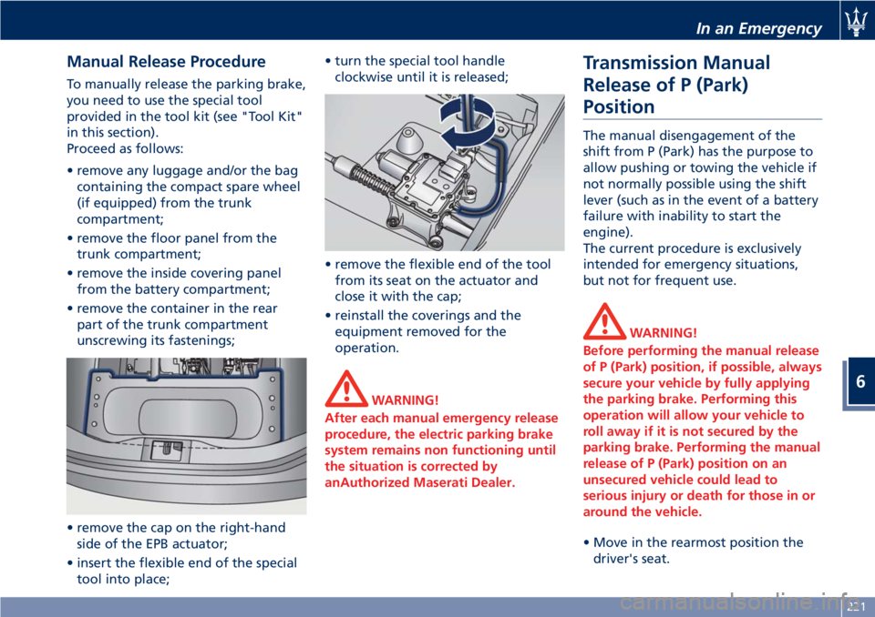
• remove any luggage and/or the bag
containing the compact spare wheel
(if equipped) from the trunk
compartment;
• remove the floor panel from the
trunk compartment;
• remove the inside covering panel
from the battery compartment;
• remove the container in the rear
part of the trunk compartment
unscrewing its fastenings;
• remove the cap on the right-hand
side of the EPB actuator;
• insert the flexible end of the special
tool into place;• turn the special tool handle
clockwise until it is released;
• remove the flexible end of the tool
from its seat on the actuator and
close it with the cap;
• reinstall the coverings and the
equipment removed for the
operation.
WARNING!
After each manual emergency release
procedure, the electric parking brake
system remains non functioning until
the situation is corrected by
anAuthorized Maserati Dealer.
Transmission Manual
Release of P (Park)
Position
The manual disengagement of the
shift from P (Park) has the purpose to
allow pushing or towing the vehicle if
not normally possible using the shift
lever (such as in the event of a battery
failure with inability to start the
engine).
The current procedure is exclusively
intended for emergency situations,
but not for frequent use.
WARNING!
Before performing the manual release
of P (Park) position, if possible, always
secure your vehicle by fully applying
the parking brake. Performing this
operation will allow your vehicle to
roll away if it is not secured by the
parking brake. Performing the manual
release of P (Park) position on an
unsecured vehicle could lead to
serious injury or death for those in or
around the vehicle.
• Move in the rearmost position the
driver's seat.
In an Emergency
6
221
Page 227 of 296
• Remove the screwdriver from the
hole, being careful not to move the
transmission shift lever.
• Shift the lever fully into N (Neutral).
This position will allow vehicle
towing.
• Reinstall all the removed electrical
parts pushing it in the central
console seat until you hear the
locking click.
• Reinstall the covering panel on the
external side of the central console
press it until all pins are engaged in
their clips and “click” in place.
CAUTION!
Work extremely carefully so as not to
damage the central console trim
panels.
Freeing the Stuck Vehicle
If your vehicle is stuck in mud, sand, or
snow, it can probably be moved
backward and forward by a simple
rocking motion.
Steer the wheel right and left to clear
the area around the front wheels.
Shift then between D (Drive) or
MANUAL mode and R (Reverse) (see
chapter “Automatic Transmission” and
“Drive Mode” in section “Driving”).
Shifting to MANUAL mode, try to free
the car starting in second gear.
At low speed motion of the vehicle,
you can switch quickly from D (Drive)
to R (Reverse), and vice versa, just by
pressing the release button on the
shift lever.
For more effectiveness press lightly on
the accelerator pedal in order to avoid
wheel slippage.
If unable to release the vehicle in one
of the previously described ways,
enter the low-grip driving mode, by
pressing the “ICE” button, and
completely exclude the yaw and slip
control system, by pressing the
(ESC
Off) button for at least 2 seconds.
Moving the shift lever between D
(Drive) and R (Reverse) to start.
CAUTION!
Racing the engine or spinning the
drive wheels may lead to transmission
overheating and failure. Allow the
engine to idle with the shift lever in N
(Neutral) for at least one minute after
every five rocking-motion cycles. This
will minimize overheating and reduce
the risk of transmission failure during
prolonged efforts to free a stuck
vehicle.
WARNING!
Fast spinning tires can be dangerous.
Forces generated by excessive drive
wheel speeds may cause damage, or
even failure, of the drivetrain and
tires.
In an Emergency
6
223
Page 228 of 296
Emergency Starting with
Maserati Code
If the Maserati CODE fails to
deactivate the engine immobilizer, the
CODE warning light will illuminate
permanently, while the
MIL
warning light will go off after four
seconds and will turn on again
immediately afterward: the engine will
not start.
To start the engine, follow the
emergency starting procedure.
Emergency Starting Procedure
NOTE:
We recommend that you carefully read
the entire procedure before
performing it. If you make a mistake,
turn the key in the ignition switch to
STOP (OFF)position and repeat the
operations from the first step.
WARNING!
California Proposition 65
Operating, servicing and maintaining
a passenger vehicle or off-road vehicle
can expose you to chemicals including
such as, engine exhaust, carbon
monoxide, phthalates and lead, thatwhich are know to the State of
California to cause cancer and birth
defects or other reproductive harm. To
minimize exposure, avoid breathing
exhaust, do not idle the engine except
as necessary, service your vehicle in a
well-ventilated area and wear gloves
or wash your hands frequently when
servicing your vehicle. For more
information go to:
www.P65Warnings.ca.gov/passenger-
vehicle
• Read the 5-digit electronic code
found on the CODE card.
• Turn the key in the ignition switch to
MAR (ON)position: at this moment
the
CODE andMIL warning
lights are on.
• Push and hold down the accelerator
pedal. Approximately 8 seconds later,
the
MIL warning light will go off.
Release the accelerator and get
ready to count the number of times
the
MIL warning light flashes.
• Wait until the number of flashes is
equal to the first digit of your CODE
card, then push and hold down the
accelerator pedal until the
MIL
warning light goes off, after about 4
seconds, then release the accelerator
pedal.• The
MIL warning light starts
flashing again. As soon as the
displayed number of flashing is equal
to the second digit of your CODE
card, press down the accelerator
pedal and hold it.
• Proceed in the same manner for the
remaining digits in the code on the
CODE card.
• When the last digit has been
entered, hold the accelerator pedal
pushed down. The
MIL warning
light comes on for 4 seconds and
then goes off; you can now release
the accelerator pedal.
• When the
MIL warning light
flashes fast (for about 4 seconds) it
confirms that the procedure has
been performed correctly.
• Start the engine by turning the key
in the ignition switch fromMAR (ON)
position toAVVposition.
If the
MIL warning light remains
on, turn the key toSTOP (OFF)position
and repeat the procedure from the
first step. This procedure can be
repeated an unlimited number of
times.
In an Emergency
6
224
Page 230 of 296

WARNING!
•Using booster packs that have not
been checked, which could therefore
release a too high charging voltage
(higher than 14 V), in extreme
environmental conditions (for
example: closed areas or without
proper ventilation and temperatures
higher than 122°F/50°C or lower
than -4°F/-20°C) create the right
conditions for ignition which could
then cause the battery to explode.
Therefore you shall always perform
jump-starting operations using the
adequate tools and in the best
environmental conditions, taking all
necessary precautions.
•Do not attempt jump-starting if the
discharged battery is frozen. It could
rupture or explode during jump start
and cause personal injury.
•Do not carry out this procedure if
you have not done it before:
incorrect maneuvers can originate
high electrical discharges and even
cause the battery to explode.
•To avoid the risk of explosion or fire,
do not approach the battery withopen flames or cigarettes that could
generate sparks.
NOTE:
If you need to disconnect the battery
from the vehicle electrical system, see
“Maintenance - Free Battery” in
section “Maintenance and Care”).
Access the Battery
The battery is stored in the trunk.
• Open the trunk lid (see “Open and
Close the Trunk Lid” in section
“Before Starting”).
• Remove any luggage from the trunk
compartment.
• Remove the floor panel from the
trunk compartment.
• Remove the inside covering panel
from the battery compartment.Remove the cover from the right side
of the battery which protects the
positive pole.
Jump-Start Procedure
WARNING!
•The battery is secured to the vehicle
with a metal clamp (indicated in the
picture), so be extremely careful not
to let the clips on the end of the
cables come into contact with it.
•Remove any metal jewelry such as
watch bands or bracelets that might
make an inadvertent electrical
contact. You could be seriously
injured.
•Do not allow the vehicles involved in
the jump-starting operation to touch
each other as this could establish a
ground connection and cause
personal injury.
• Turn off the heater, radio, and all
unnecessary electrical accessories.
• Set the parking brake, shift the
automatic transmission into P (Park)
and turn the key in the ignition
switch toSTOP (OFF)position.
• If using another vehicle to jump start
the battery, park the vehicle within
In an Emergency
6
226
Page 231 of 296

the jumper cables reach and set the
parking brake and make sure the
ignition is off.
• Connect one terminal clamp of the
positive jumper cable to the positive
(+) pole of the discharged battery.
• Connect the opposite terminal clamp
of the positive (+) jumper cable to
the positive (+) pole of the booster
battery.
• Connect one terminal clamp of the
negative jumper cable to the
negative (–) pole of the booster
battery.
• Connect the opposite terminal clamp
of the negative (–) jumper cable to
the negative (–) pole of the
discharged battery.
• Start the engine in the vehicle that
has the booster battery, let the
engine idle a few minutes, and then
start the engine in the vehicle withthe discharged battery. If using a
portable battery booster, wait a few
seconds after connecting the cables,
before starting the booster vehicle.
Once the engine is started, remove the
jumper cables in the reverse sequence.
• Disconnect the terminal clamp of the
negative (–) jumper cable from the
negative (–) pole of the discharged
battery.
• Disconnect the opposite terminal
clamp of the negative jumper cable
from the negative (–) pole of the
booster battery.
• Disconnect the terminal clamp of the
positive (+) jumper cable from the
positive (+) pole of the booster
battery.
• Disconnect the terminal clamp of the
positive jumper cable from the
positive (+) pole of the discharged
battery.
• After starting the engine of the
vehicle with a discharged battery,
avoid turning it off immediately
because the engine running can help
recharge the battery if the latter is
not broken and if the charging
system is not faulty.NOTE:
If frequent jump-starting is required
to start your vehicle you should have
the battery and charging system
inspected at anAuthorized Maserati
Dealer.
WARNING!
California Proposition 65
Operating, servicing and maintaining
a passenger vehicle or off-road vehicle
can expose you to chemicals including
such as, engine exhaust, carbon
monoxide, phthalates and lead, that
which are know to the State of
California to cause cancer and birth
defects or other reproductive harm. To
minimize exposure, avoid breathing
exhaust, do not idle the engine except
as necessary, service your vehicle in a
well-ventilated area and wear gloves
or wash your hands frequently when
servicing your vehicle. For more
information go to:
www.P65Warnings.ca.gov/passenger-
vehicle
In an Emergency
6
227
Page 233 of 296
Use the Vehicle Tow Hook of
the Tool Kit
CAUTION!
The tow hook should only be used for
towing the car on flat roads. Do not
use the tow hook to remove the car
that is stuck on off road stretches.
The tow hook can also be used to tow
the vehicle on the platform of a tow
truck.
It is necessary to inform the operators
of the rescue vehicle about the vehicle
minimum height to avoid, during its
loading, any contact of the lower ends
of the front or rear bumper with the
tow truck loading ramp.
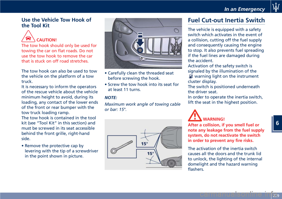
The tow hook is contained in the tool
kit (see “Tool Kit” in this section) and
must be screwed in its seat accessible
behind the front grille, right-hand
side.
• Remove the protective cap by
levering with the tip of a screwdriver
in the point shown in picture.• Carefully clean the threaded seat
before screwing the hook.
• Screw the tow hook into its seat for
at least 11 turns.
NOTE:
Maximum work angle of towing cable
or bar: 15°.
Fuel Cut-out Inertia Switch
The vehicle is equipped with a safety
switch which activates in the event of
a collision, cutting off the fuel supply
and consequently causing the engine
to stop. It also prevents fuel spreading
if the fuel lines are damaged during
the accident.
Activation of the safety switch is
signaled by the illumination of the
warning light on the instrument
cluster display.
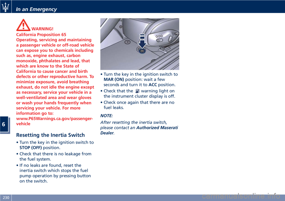
The switch is positioned underneath
the driver seat.
In order to operate the inertia switch,
lift the seat in the highest position.
WARNING!
After a collision, if you smell fuel or
note any leakage from the fuel supply
system, do not reactivate the switch
in order to prevent any fire risks.
The activation of the inertia switch
causes all the doors and the trunk lid
to unlock, the lighting of the internal
domelight and the hazard warning
flashers.
In an Emergency
6
229
Page 234 of 296
WARNING!
California Proposition 65
Operating, servicing and maintaining
a passenger vehicle or off-road vehicle
can expose you to chemicals including
such as, engine exhaust, carbon
monoxide, phthalates and lead, that
which are know to the State of
California to cause cancer and birth
defects or other reproductive harm. To
minimize exposure, avoid breathing
exhaust, do not idle the engine except
as necessary, service your vehicle in a
well-ventilated area and wear gloves
or wash your hands frequently when
servicing your vehicle. For more
information go to:
www.P65Warnings.ca.gov/passenger-
vehicle
Resetting the Inertia Switch
• Turn the key in the ignition switch to
STOP (OFF)position.
• Check that there is no leakage from
the fuel system.
• If no leaks are found, reset the
inertia switch which stops the fuel
pump operation by pressing button
on the switch.• Turn the key in the ignition switch to
MAR (ON)position: wait a few
seconds and turn it toACCposition.
• Check that the
warning light on
the instrument cluster display is off.
• Check once again that there are no
fuel leaks.
NOTE:
After resetting the inertia switch,
please contact anAuthorized Maserati
Dealer.
In an Emergency
6
230
Page 239 of 296

Service coupons 1° 2° 3° 4° 5° 6° 7° 8° 9° 10° 11° 12°
Main operations Maintenance schedules: every 12500 mi (20000 km) or 2 years
Air injection system: connections and pipes
valvesIIIIIIIIIIII
Blow-by systemIII II
Fuel emission control system: lines,
connections and valvesIII III
Automatic transmission oil levelIIIIIIIIIIII
Differential oil levelIIIIIIIIIIII
Hydraulic steering fluid level (bleed if
necessary)IIIIIIIIIIII
Replace at least every 2 years
Engine coolant levelIIIIIIIIIIII
Replace at least every 2 years
Brake fluid level (bleed if necessary)IIIIIIIIIIII
Replace at least every 2 years
Brake system: lines, calipers, connections -
Efficiency of the dashboard warning lights
- Parking brake operationIIIIIIIIIIII
Wear condition of the braking parts
(rotors, pads); replace if necessaryIIIIIIIIIIII
Joints for front and rear suspensions, front
and rear under-chassis – Tightening
torquesIIIIIIIIIIII
Steering system components, joint
protection, rack trunks on the steering
levers and on the axle shaftsIIIIIIIIIIII
Maintenance and Care
7
235