2020 MASERATI GRANTURISMO CONVERTIBLE fuses
[x] Cancel search: fusesPage 107 of 296
blow the fuse. Damages caused by
improper use of the power outlet
are not covered by the New Vehicle
Limited Warranty.
WARNING!
To avoid serious injury or death:
•Only devices designed for use in this
type of outlet should be inserted
into any 12 Volt outlet.
•Replacing the fuses that protect
power outlets with others of higher
amperage, there is the risk of fire.
•Do not touch with wet hands.
•If this outlet is mishandled, it may
cause an electric shock and failure.
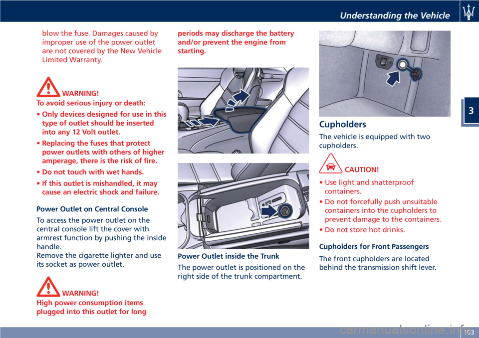
Power Outlet on Central Console
To access the power outlet on the
central console lift the cover with
armrest function by pushing the inside
handle.
Remove the cigarette lighter and use
its socket as power outlet.
WARNING!
High power consumption items
plugged into this outlet for longperiods may discharge the battery
and/or prevent the engine from
starting.
Power Outlet inside the Trunk
The power outlet is positioned on the
right side of the trunk compartment.
Cupholders
The vehicle is equipped with two
cupholders.
CAUTION!
• Use light and shatterproof
containers.
• Do not forcefully push unsuitable
containers into the cupholders to
prevent damage to the containers.
• Do not store hot drinks.
Cupholders for Front Passengers
The front cupholders are located
behind the transmission shift lever.
Understanding the Vehicle
3
103
Page 177 of 296
When the system refuses to engage a
gear, an acoustic signal will sound for
a few seconds.
Sequential manual operation can only
be selected from the D (Drive) position
whatever the function (SPORT,
NORMAL) active at the time of the
request. The gear selected by the
automatic transmission will remain
engaged when the transmission shift
lever is moved.
Shifting the lever back to D (Drive),
automatic operation will instantly be
resumed, and a gear will be engaged
based on the driving style and mode
selected.
In the event of a failure of the
sequential manual gearshift system,
the transmission ECU will select
automatic operation.
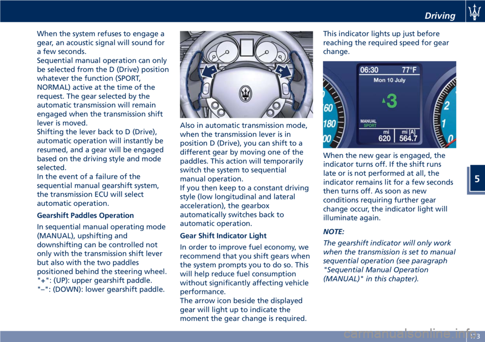
Gearshift Paddles Operation
In sequential manual operating mode
(MANUAL), upshifting and
downshifting can be controlled not
only with the transmission shift lever
but also with the two paddles
positioned behind the steering wheel.
"+": (UP): upper gearshift paddle.
"–": (DOWN): lower gearshift paddle.Also in automatic transmission mode,
when the transmission lever is in
position D (Drive), you can shift to a
different gear by moving one of the
paddles. This action will temporarily
switch the system to sequential
manual operation.
If you then keep to a constant driving
style (low longitudinal and lateral
acceleration), the gearbox
automatically switches back to
automatic operation.
Gear Shift Indicator Light
In order to improve fuel economy, we
recommend that you shift gears when
the system prompts you to do so. This
will help reduce fuel consumption
without significantly affecting vehicle
performance.
The arrow icon beside the displayed
gear will light up to indicate the
moment the gear change is required.This indicator lights up just before
reaching the required speed for gear
change.
When the new gear is engaged, the
indicator turns off. If the shift runs
late or is not performed at all, the
indicator remains lit for a few seconds
then turns off. As soon as new
conditions requiring further gear
change occur, the indicator light will
illuminate again.
NOTE:
The gearshift indicator will only work
when the transmission is set to manual
sequential operation (see paragraph
"Sequential Manual Operation
(MANUAL)" in this chapter).
Driving
5
173
Page 255 of 296

Fuse Replacement
Used Fuses Characteristics
When an electrical device is not
functioning, check that the
corresponding fuse is in proper
working order (intact).
AFuse intact
BFuse blown
Replace the faulty fuse with a new
one featuring the same rating, by
using appropriate forceps.The color identifies the value of the
fuses in amperes which is also
reported on them.
The vehicle is endowed with mini- and
maxi-fuses.
The table shows the match between
color and amperage of mini and maxi
fuses.
Type
Mini Fuse Maxi Fuse
Beige - 5 Yellow - 20
Brown - 7.5 Green - 30
Red - 10 Orange - 40
Blue-15 Red-50
Yellow - 20 Blue - 60
White - 25
Green - 30
CAUTION!
• Never replace a blown fuse with
anything other than a new and
suitable fuse (same rating).
• After replacing a fuse, if the fault
recurs, contact anAuthorized
Maserati Dealer.
Position of Fuses
The fuses are located in three parts of
the vehicle, namely:
• On the right hand side of the engine
compartment.
• Behind the glove compartment, to
the left of the steering wheel.
• In the trunk compartment next to
the battery.
Fuses Inside Engine
Compartment
• To access the fuses, lift the hood and
remove the covering panel.
Maintenance and Care
7
251
Page 256 of 296
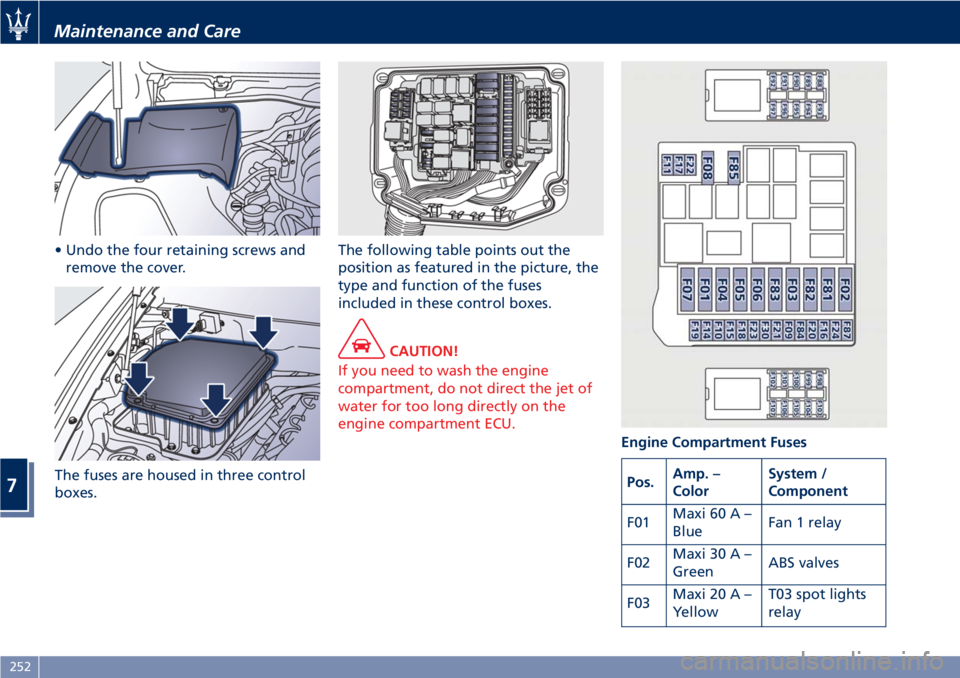
• Undo the four retaining screws and
remove the cover.
The fuses are housed in three control
boxes.The following table points out the
position as featured in the picture, the
type and function of the fuses
included in these control boxes.
CAUTION!
If you need to wash the engine
compartment, do not direct the jet of
water for too long directly on the
engine compartment ECU.
Engine Compartment Fuses
Pos.Amp. –
ColorSystem /
Component
F01Maxi 60 A –
BlueFan 1 relay
F02Maxi 30 A –
GreenABS valves
F03Maxi 20 A –
YellowT03 spot lights
relay
Maintenance and Care
7
252
Page 258 of 296
Pos.Amp. –
ColorSystem /
Component
F107 - Not used
Fuses in Passenger
Compartment
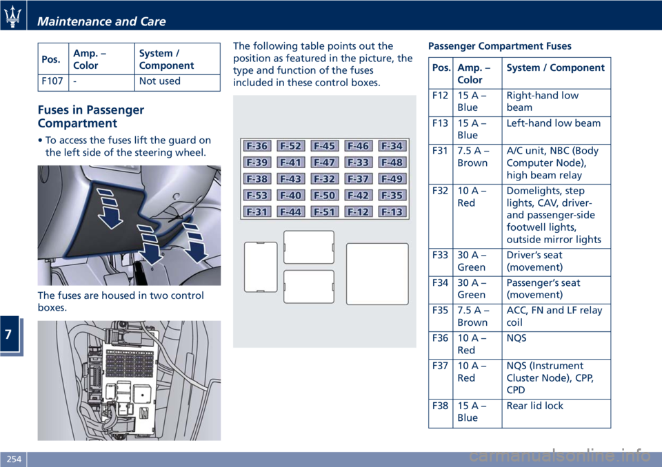
• To access the fuses lift the guard on
the left side of the steering wheel.
The fuses are housed in two control
boxes.The following table points out the
position as featured in the picture, the
type and function of the fuses
included in these control boxes.Passenger Compartment Fuses
Pos. Amp. –
ColorSystem / Component
F12 15 A –
BlueRight-hand low
beam
F13 15 A –
BlueLeft-hand low beam
F31 7.5 A –
BrownA/C unit, NBC (Body
Computer Node),
high beam relay
F32 10 A –
RedDomelights, step
lights, CAV, driver-
and passenger-side
footwell lights,
outside mirror lights
F33 30 A –
GreenDriver’s seat
(movement)
F34 30 A –
GreenPassenger’s seat
(movement)
F35 7.5 A –
BrownACC, FN and LF relay
coil
F36 10 A –
RedNQS
F37 10 A –
RedNQS (Instrument
Cluster Node), CPP,
CPD
F38 15 A –
BlueRear lid lock
Maintenance and Care
7
254
Page 259 of 296

Pos. Amp. –
ColorSystem / Component
F39 15 A –
BlueNIM (Inside Roof
Node), NCL (Air
conditioning and
heating system
node), OBD socket,
CSA (Alarm system
siren ECU), CAV
(Motion sensing
alarm ECU), radio,
NAVTRAK
F40 30 A –
GreenHeated rear window
F41 - Not used
F42 7.5 A –
BrownNCL and windshield
wiper control
F43 30 A –
GreenWindshield
wiper/washer
(Connected Devices
Relay INT/A)
F44 20 A –
YellowFront and rear power
outlets (INT/A device
relay) front seat
heating (passenger
side)
F45 - Not used
F46 20 A –
YellowNPG/NPP locksPos. Amp. –
ColorSystem / Component
F47 30 A –
GreenNPG (Driver’s door
node)
F48 30 A –
GreenNPP (Passenger’s
door node)
F49 7.5 A –
BrownNVO (Steering wheel
node), CSG (Power
steering ECU), CSP
(Twilight/rain sensor
ECU), NIM (Inside
Roof Node), NCL,
Radio, CEM, CRP,
domelight molding,
NAVTRAK
F50 7.5 A –
BrownAir bag system
F51 7.5 A –
BrownNCA (Automatic
Gearbox Node)
F52 15 A –
BlueFront seat heating
(driver side) (INT/A
device relay)
F53 10 A –
RedRear fog lights
Fuses in Trunk Compartment
• To access the fuses, remove the floor
panel.• Remove the inside covering panel of
the battery compartment.
There are two control boxes.
• To access the fuses inside the control
boxes, remove the covers by levering
up the fastening tabs.
Maintenance and Care
7
255
Page 260 of 296
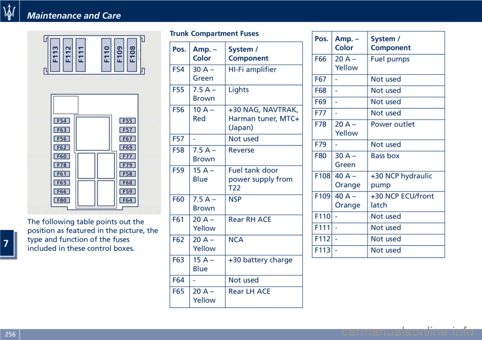
The following table points out the
position as featured in the picture, the
type and function of the fuses
included in these control boxes.Trunk Compartment Fuses
Pos. Amp. –
ColorSystem /
Component
F54 30 A –
GreenHI-Fi amplifier
F55 7.5 A –
BrownLights
F56 10 A –
Red+30 NAG, NAVTRAK,
Harman tuner, MTC+
(Japan)
F57 - Not used
F58 7.5 A –
BrownReverse
F59 15 A –
BlueFuel tank door
power supply from
T22
F60 7.5 A –
BrownNSP
F61 20 A –
YellowRear RH ACE
F62 20 A –
YellowNCA
F63 15 A –
Blue+30 battery charge
F64 - Not used
F65 20 A –
YellowRear LH ACE
Pos. Amp. –
ColorSystem /
Component
F66 20 A –
YellowFuel pumps
F67 - Not used
F68 - Not used
F69 - Not used
F77 - Not used
F78 20 A –
YellowPower outlet
F79 - Not used
F80 30 A –
GreenBass box
F108 40 A –
Orange+30 NCP hydraulic
pump
F109 40 A –
Orange+30 NCP ECU/front
latch
F110 - Not used
F111 - Not used
F112 - Not used
F113 - Not used
Maintenance and Care
7
256
Page 291 of 296

Jump Starting Procedure......225
ToolKit..................212
Towing a Disabled Vehicle.....228
Engine
Engine Air Filter Replacement . .245
Engine Coolant Level Check. . . .240
Engine Oil Level Check.......243
Engine Overheating.........214
Engine Start Failure.........159
Engine Turn Off............159
Hood, Open and Close........37
Normal Starting of the Engine . .158
Use of the Engine...........183
EPB (Electric Parking Brake)......174
ESC (Electronic Stability Control) . .177
Filters
A/C Air Filter Replacement.....263
Engine Air Filter Replacement . .245
Fuel
Carbon Monoxide Warning. . . .201
Emergency Fuel Filler Door
Release..................203
Fuel Consumption Data.......278
Fuel Requirements..........199
Fuel System Warnings........201
Gasoline/Oxygenate Blends. . . .200
Materials Added to Fuel......201
MMT in Gasoline...........200
Reformulated Gasoline.......200
Fuses Position and Replacement. . .251
HomeLink..................108Hood, Open and Close..........37
Indicator Lights
Air bag Warning Light........66
Indicator Lights/Warning Lights
TFT Display: Warning/Indicator
Lights...................126
Warning and Indicator Lights on
Analog Instrument..........119
Inertia Switch, Fuel Cut-out......229
Infotainment System..........130
Manual Controls and Devices . .132
Installing a LATCH-Compatible
Child Restraint System.........57
Instrument Cluster............118
Interior Components...........70
Interior Maintenance and Cure . . .268
Interiors Features.............102
Jump Start Procedure.........
.226
Keys
......................22
Level Checks................240
Adding Windshield/Headlight
Washer..................243
Brake Fluid Level Check.......242
Engine Coolant Level Check. . . .240
Engine Oil Level Check.......240
Power Steering Fluid Level
Check...................245
Transmission Oil Check.......245
Lights.....................82Adaptive Bi-Xenon Headlights . . .84
Automatic Headlights.........84
Bulb Replacement..........257
Cargo Light................88
DRL, Daytime Running Lights....83
Front Domelights............87
Hazard Warning Flasher.......88
Headlights................84
High Beams and Flashing......86
Light Switch...............82
Parking Lights..............84
Rear Fog Lights.............85
Turn Signals................86
Twilight Sensor.............85
Loading the Vehicle
Vehicle Load Carrying Capacity . .107
Maintenance
A/C System Maintenance......262
Bodywork Maintenance and
Care....................265
Interior Maintenance and Care . .268
Maintenance Procedures......239
Periodic Maintenance........237
Scheduled Maintenance
Service..................232
Scheduled Service Plan.......234
Wheels Maintenance........263
Maserati Roadside Assistance
Program...................15
MIL (Malfunction Indicator Light). .119
Mirrors
Folding Mirrors.............81
Index
9
287