Page 9 of 66

INSTRUMENT CLUSTER
7
Images are for illustrative purposes only and may not reflect actual feature or operation.
TIRE PRESSURE MONITORING VIDEO
To view a video on your mobile device, snap this QR Code or visit the listed website. Refer to page 2 for more information.
Tire Pressure Monitoring System (TPMS)† 26
The TPMS indicator functions as both Low Tire Pressure
Light and TPMS Malfunction Indicator.
The TPMS indicator is designed to illuminate if it detects
one or more tires is significantly underinflated, if a spare
tire has been installed that does not have a TPMS device,
or when the outside temperature drops considerably.
The LCD screen in the instrument cluster will display the
Low Tire Pressure indicator A showing which tire(s) is
underinflated.
§ Inflate tire(s) to specifications using an accurate digital
tire pressure gauge. See front driver’s door jamb for
PSI specification
§ When there is a problem with the TPMS, the TPMS
Malfunction Indicator will blink for approximately one
minute then illuminate. See dealer for service
Quick Tips
§ Even with TPMS, tire pressure should be checked manually at least once a month. Only adjust tire pressure on “cold tires” that have been sitting for 20 minutes, and tires that are not hot in temperature from direct sunlight or heat
§
For proper maintenance, safety and optimal fuel economy, maintain recommended tire inflation pressure and stay within the load limits and weight distribution recommended for your vehicle
§
In winter or cold weather, the TPMS light may illuminate if the tire pressure was adjusted to the recommended tire inflation pressure during warm weather
REMINDERS:
§ Check the recommended tire pressure label located on the left side of driver’s door jamb, visible when the door is open
§ Consult your dealer for service if the Low Tire Pressure Light remains illuminated after inflating your tire(s)
§ Personal electronic devices (such as laptops, wireless chargers, remote start systems, etc.) may interfere with the TPMS system, which may cause the Malfunction Warning Indicator (Check Engine Light) to illuminate
Low Tire Pressurepsi
24
35 35
35
A
www.youtube.com/KiaFeatureVideos
ALWAYS CHECK THE OWNER’S MANUAL FOR COMPLE TE OPERATING INFORMATION AND SAFETY WARNINGS.*IF EQUIPPED†LEG AL DISCL AIMERS ON BACK INSIDE COVER
Page 10 of 66

MODECRUISE
CANCEL
RES
OK SET
CRUISE
CANCEL
RES
OK SET
MODE CRUISE
CANCEL
RES
OK SET
MODECRUISE
CANCEL
RES
OK SET
MODECRUISE
CANCEL
RES
OK SET
INSTRUMENT CLUSTER
LCD Instrument Cluster Modes*
The LCD Instrument Cluster modes can be
changed by using the mode button A on the
right side of the steering wheel.
Trip Information / Trip Computer
The Trip Computer is a driver information system that
displays information related to driving when the Engine
Start /Stop button is in the ON position.
To cycle through the LCD Instrument Cluster modes,
press the Mode button A on the right side of the
steering wheel.
When in the Trip Computer mode , press the Select /
Reset (OK ) button B to cycle through the screens.
When displaying TRIP A or TRIP B screens, press and
hold the OK button to reset the Tripmeter to zero.
REMINDERS:
§ Appearance of Tripmeter display may differ as equipped
§ All stored driving information (except Odometer and Range) is reset if the battery is disconnected
Trip Computer Mode: Displays driving information for tripmeter, fuel economy, etc.
Turn-by-Turn Mode*: Displays the route guidance and destination info
Assist: Displays the Lane Safety, Driver Attention Warning, AWD and TPMS info
User Settings Mode: Change settings of the Head-Up Display, Driver Assistance, doors, lights, sound, convenience, service interval and other features
Master Warning Mode: Displays warning messages related to the vehicle when one or more systems is not operating normally
Your vehicle’s steering wheel buttons and LCD modes may differ from those in the illustrations.
Driving while distracted is dangerous and should be avoided. Drivers should remain attentive to driving and always exercise caution when using the steering-wheel- mounted controls while driving.
Drive Info• Tr ipme t e r • Average Fuel Economy • Timer
Accumulated Info• Tr ipme t e r • Average Fuel Economy • Timer
FUEL ECONOMY• Average Fuel Economy • Instant Fuel Economy
Drive Mode
Digital Speedometer
(Modes on Instrument Cluster LCD)
A
B
*IF EQUIPPED8
Displays the route guidance and destination info:
Page 11 of 66

INSTRUMENT CLUSTER
9*IF EQUIPPED ALWAYS CHECK THE OWNER’S MANUAL FOR COMPLE TE OPER ATING INFORMATION AND SAFE T Y WARNINGS.
To enter the User Settings mode in the LCD
Instrument Cluster Modes, press the Mode
button A when the vehicle is at a standstill
and with the Engine Start /Stop button in the
ON position and select User Settings .
You can navigate the selections on the display
by pressing the Select /Reset (OK ) button B up
or down, and then pressing again to enter.
User Settings Modes:
Head-Up Display (HUD)*: Enable HUD, Display Height, Rotation, Brightness, Contents Selection, Speedometer Size, Speedometer Color
Driver Assistance: Smart Cruise Control Response, Driver Assist, Driver Attention Warning, Warning Timing, Warning Volume, Lane Safety, Forward Safety, Blind-Spot Safety, Parking Safety
Door/Liftgate: Automatic Lock, Automatic Unlock, Two-press Unlock*, Power Liftgate*, Power Liftgate Speed*, Smart Power Liftgate*
Lights: One-Touch Turn Signal, Headlamp Delay
Sound: Welcome Sound*
Convenience: Seat Easy Access*, Rear Occupant Alert, Welcome Mirror/Light*, Wiper/Light Display*, Auto Rear Wiper, Gear Position Pop-Up*, Icy Road Warning*
Service Interval: Enable Service Interval, Adjust Service Interval, Reset
Other: Fuel Economy Auto Reset, Fuel Economy Unit, Temperature Unit, Tire Pressure Unit
Reset: Reset User Settings to factory default
When Service Interval Mode is activated and set, and vehicle service is required, the LCD will display the
message Service Required and the remaining days/miles until service is due.
Service Interval Mode ON and Interval Setting
To activate Service Interval Mode and set the interval, press the Mode button A, scroll to User Settings
and press Select /Reset (OK ) button B to enter. Then press the OK button B up/down to scroll to Service
Mode and again to enter. Press OK button B up/down to select the option to set the interval. Adjust
interval and press OK button B to save. To reset the Service Mode system, press and hold the OK button B for more than 1 second.
Service Interval Mode Off
To turn Service Required OFF, go to User Settings and scroll to Service Interval Mode, press OK button B
to enter. Select option to deactivate and press OK button B to save.
User Settings - Instrument Cluster
Service Interval Mode
MODECRUISE
CANCEL
RES
OK SET
CRUISE
CANCEL
RES
OK SET
MODE CRUISE
CANCEL
RES
OK SET
MODECRUISE
CANCEL
RES
OK SET
MODECRUISE
CANCEL
RES
OK SET
A
B
To view videos on your mobile device, snap these QR Codes or visit the listed website. Refer to page 2 for more information.
LCD DISPLAY VIDEO
LCD DISPLAY: MAINTENANCE VIDEO
(Button layout on right of steering wheel)
www.youtube.com/KiaFeatureVideos
Page 12 of 66
 System
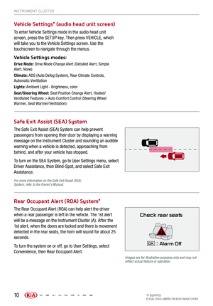
Vehicle Settings* (audio head unit screen)
Rear Occupant Alert (ROA) System*
The Safe Exit As")
INSTRUMENT CLUSTER
10*IF EQUIPPED†LEG AL DISCL AIMERS ON BACK INSIDE COVER
Safe Exit Assist (SEA) System
Vehicle Settings* (audio head unit screen)
Rear Occupant Alert (ROA) System*
The Safe Exit Assist (SE A) System can help prevent
passengers from opening their door by displaying a warning
message on the Instrument Cluster and sounding an audible
warning when a vehicle is detected, approaching from
behind, and after your vehicle has stopped.
To turn on the SE A System, go to User Settings menu, select
Driver Assistance, then Blind-Spot, and select Safe Exit
Assistance.
To enter Vehicle Settings mode in the audio head unit
screen, press the SETUP key. Then press VEHICLE, which
will take you to the Vehicle Settings screen. Use the
touchscreen to navigate through the menus.
Vehicle Settings modes:
Drive Mode: Drive Mode Change Alert (Detailed Alert, Simple Alert, None)
Climate: ADS (Auto Defog System), Rear Climate Controls, Automatic Ventilation
Lights: Ambient Light - Brightness, color
Seat/Steering Wheel: Seat Position Change Alert, Heated/Ventilated Features > Auto Comfort Control (Steering Wheel Warmer, Seat Warmer/ Ventilation)
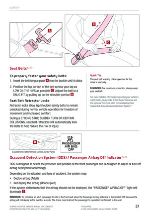
The Rear Occupant Alert (ROA) can help alert the driver
when a rear passenger is left in the vehicle. The 1st alert
will be a message on the Instrument Cluster (A). After the
1st alert, when the doors are locked and there is movement
detected in the rear seats, the horn will sound for about 25
seconds.
To turn the system on or off, go to User Settings, select
Convenience, then Rear Occupant Alert.
Images are for illustrative purposes only and may not reflect actual feature or operation.
For more information on the Safe Exit Assist (SEA) System, refer to the Owner’s Manual.
Check rear seats
: Alarm OffOK
Page 13 of 66
†6 /
Forward Collision Warning (FCW)†6
FCA-Ped is designed to help alert the driver and, under
certain conditions, ap")
INSTRUMENT CLUSTER
11
Forward Collision-Avoidance Assist-Pedestrian (FCA-Ped)†6 /
Forward Collision Warning (FCW)†6
FCA-Ped is designed to help alert the driver and, under
certain conditions, apply emergency braking when rapidly
approaching a vehicle that is slowing down, braking or
stopped or if it detects a pedestrian in front of the vehicle.
Initially, FCA-Ped provides Forward Collision Warning
(FCW ) when it detects a potential collision with a vehicle
or a pedestrian in front, emitting an audible warning and
visual alert on the instrument cluster A. Adjust the alert
settings (Active Assist, Warning Only, Off) in the User
Settings. To turn FCA-Ped/FCW off, go to User Settings
again and turn off.
If the system detects that the collision risk has increased,
Forward Collision-Avoidance Assist-Pedestrian (FCA-Ped)
automatically applies the brakes to reduce your speed,
potentially helping to minimize the effects of a possible
collision. FCA-Ped can be turned ON in the User Settings
menu on the Instrument Cluster display.
FCA-Ped/FCW will become active when the:
§ Engine Start /Stop button is ON
§ Vehicle is traveling faster than 5 mph
§ Electronic Stability Control (ESC) is ON
LED Warning Messages:
REMINDERS:
§ FCA-Ped/FCW will be activated by default when the ignition is cycled ON, even when previous setting was OFF
§ FCA-Ped/FCW will not operate when the vehicle is traveling faster than approximately 45/50 mph, respectively
§ If FCA-Ped is operating and the ESC (Electronic Stability Control) is turned off B, FCA-Ped system is automatically turned off
§ When the FCA-Ped system is off, the FCA-Ped warning indicator is on in the Instrument Cluster
The Forward Collision-Avoidance Assist-Pedestrian (FCA-Ped) / Forward Collision Warning (FCW) systems are not substitutes for safe and proper driving. Always drive safely and use Caution.
FCA-Ped and FCW may not always alert the driver when the vehicle is approaching another vehicle.
Images are for illustrative purposes only and may not reflect actual feature or operation.
Collision Warning
Emergency Braking
A
ALWAYS CHECK THE OWNER’S MANUAL FOR COMPLE TE OPERATING INFORMATION AND SAFETY WARNINGS.*IF EQUIPPED
FORWARD COLLISION-AVOIDANCE ASSIST-PEDESTRIAN VIDEO
To view a video on your mobile device, snap this QR Code or visit the listed website. Refer to page 2 for more information.www.youtube.com/KiaFeatureVideos
Page 14 of 66
 User Settings
Drivers can adjust the HUD settings from the LCD Instrument
Cluster modes in User Settings. HUD settings include:
§ Display Height: Adjust the height of the HUD")
Head-Up Display (HUD) User Settings
Drivers can adjust the HUD settings from the LCD Instrument
Cluster modes in User Settings. HUD settings include:
§ Display Height: Adjust the height of the HUD image on
the windshield glass
§ Rotation: Adjust the degree of HUD rotation
§ Brightness: Adjust the intensity of the HUD brightness
§ Contents Select: Activate or deactivate HUD content
§ Speed Size: Choose the size of the HUD speedometer
§ Speed Color: Choose the color of the HUD
speedometer
INSTRUMENT CLUSTER
The head up display is a supplemental system. Do not solely rely on the system, always drive safely, and pay attention to the driving conditions on the road.
Images are for illustrative purposes only and may not reflect actual feature or operation.
REMINDERS:
§
The HUD image on the windshield glass may not be visible in these cases:
§
The driver has poor sitting posture
§ The driver is wearing polarized sunglasses
§ There is an object covering the HUD
§ Driving on a wet road
§ Excessive lighting inside or outside the vehicle
§ Modifications made to the windshield, such as tinting or other aftermarket treatments, could affect the HUD. When replacing the front windshield glass of vehicles equipped with the HUD, owners must replace it with windshield glass designed for HUD operation. Otherwise, duplicated images may be displayed on the windshield glass
§ If Turn By Turn ( TBT ) navigation information is selected as HUD content, TBT information will not be displayed on the LCD
Head-Up Display (HUD)*† 12
The Head-Up Display (HUD) is a semi-transparent display
that projects a snippet of information from the instrument
cluster and navigation system* onto the windshield glass.
To turn HUD ON or OFF, go to User Settings in the LCD Modes.
The HUD displays:
§ Turn By Turn ( TBT )
navigation information
§ Road signs*
§ Speedometer
§ Cruise setting speed*
§ Smart Cruise Control
(SCC) information*
§ Blind-Spot Collision
Warning (BCW ) system
information*
§ Lane Keeping Assist (LK A)
information*
§ Highway Driving Assist
(HDA) system information*
§ HDA system steering
control information*
§ HDA system automatic
speed setting information*
§ Warning lights (low fuel)
§ AV mode information
MPH
0.5 mi
FM
95.7
60
60HDA
SPEED LIMITAUTO
*IF EQUIPPED†LEG AL DISCL AIMERS ON BACK INSIDE COVER12
Page 15 of 66

INSTRUMENT CLUSTER
13*IF EQUIPPED ALWAYS CHECK THE OWNER’S MANUAL FOR COMPLE TE OPER ATING INFORMATION AND SAFE T Y WARNINGS.
REMINDERS:
§ If the driver changes the speed while in automatic speed setting mode, it deactivates and enters a manual mode
§ When the ignition is cycled, the system returns to its previous state, on or off
C
E
F
Highway Driving Assist is not a substitute for safe driving, may not detect all objects around the vehicle, and only functions on certain federal highways. Always drive safely and use caution. See the Owner’s Manual for more detailed information, limitations and conditions.
Images are for illustrative purposes only and may not reflect actual feature or operation.
Highway Driving Assist (HDA) System*
The Highway Driving Assist (HDA) system is designed to adjust
the speed of the vehicle when driving on federal highways.
The system can adjust the vehicle’s speed based on available
highway speed information. The automatic speed setting mode
is designed to set the speed automatically by adjusting to the
changing speed limits of the highway section.
To turn the HDA system on, go to User Settings in the
Instrument Cluster. Go to Drive Assistance > Driving Assist
> Highway Driving Assist and press the OK button B on the
Steering Wheel.
The HDA system will operate only when these conditions
are met:
§ The vehicle is traveling slower than 95 mph
§ When driving on federal highways
§ When the SCC is on and operating
§ When the SCC speed is set to current federal highway
speed
When the HDA system is activated and the conditions are met,
the Instrument Cluster indicator light C will illuminate green. If
the conditions are not met, the HDA system will be in standby
mode and the indicator light C will illuminate white.
When in operation, and if both lanes are recognized, a display E will show the lanes illuminated white and the steering
wheel indicator illuminated green.
If HDA is activated, conditions are met and the SCC speed is
set by the driver (at the posted highway speed limit or slower),
the HDA system will enter the automatic speed setting mode.
The set speed and AUTO will be displayed F in green and an
audible alert will sound.
REMINDER: HAC does not operate when the gear shift is in P (Park) or N (Neutral) position.
60mph
mph
MODECRUISE
CANCEL
RES
OK SET
CRUISE
CANCEL
RES
OK SET
MODE CRUISE
CANCEL
RES
OK SET
MODECRUISE
CANCEL
RES
OK SET
MODECRUISE
CANCEL
RES
OK SET
MODE CRUISE
CANCEL
RES
OK SET
CRUISE
CANCEL
RES
OK SET
MODE CRUISE
CANCEL
RES
OK SET
MODECRUISE
CANCEL
RES
OK SET
MODECRUISE
CANCEL
RES
OK SET
A
B
Page 16 of 66

DRIVER’S PANEL
14
ELECTRONIC STABILITY CONTROL VIDEO
To view a video on your mobile device, snap this QR Code or visit the listed website. Refer to page 2 for more information.www.youtube.com/KiaFeatureVideos
Instrument Cluster Control (Instrument Panel Dimmer)
With the Engine Start /Stop button on or the parking lights/headlights on, press A (+) or (-) to adjust the
brightness of the instrument panel illumination.
Electronic Stability Control (ESC)†8 /
Traction Control System (TCS)†8
Electronic Stability Control (ESC) is designed to help
stabilize the vehicle during certain cornering maneuvers.
Traction Control System ( TCS) can help improve traction.
It is a good idea to keep both ESC and TCS turned on
for daily driving whenever possible.
Press the ESC button B to turn Traction Control System OFF/ON.
To turn both Electronic Stability Control and Traction Control System OFF, press and hold the ESC button for
more than 3 seconds. Press again to turn ON.
REMINDERS:
§ ESC is active by default at vehicle startup. When ignition is cycled, ESC will turn ON again
§ The ESC indicator light in the instrument cluster will be lit momentarily whenever ESC is active
Hill-start Assist Control (HAC)†8
Hill-start Assist Control (HAC) is designed to prevent the vehicle from rolling
backwards when accelerating from a stop while on a steep incline.
HAC automatically activates whether ESC is OFF or ON but does NOT
activate when ESC has malfunctioned.
Quick Tip
When HAC is active (e.g., during initial acceleration from a stop on an incline), you may notice that the brakes will momentarily remain engaged after you depress the accelerator. HAC does not replace the need to apply brakes while stopped on an incline.
(Button located on driver’s panel, left of the steering wheel)
REMINDERS:
§ HAC does not operate when the gear shift is in P (Park) or N (Neutral) position
§ HAC does not replace the need to apply brakes while the vehicle is stopped on an incline
For more information on Electronic Stability Control (ESC) and its specific features and operations, please refer to the Owner’s Manual.
AB
*IF EQUIPPED†LEG AL DISCL AIMERS ON BACK INSIDE COVER