Page 452 of 635

6-16
What to do in an emergency
Always check the TPMS malfunction
LCD display after replacing one or
more tires or wheels on your vehicle
to ensure that the replacement or
alternate tires and wheels allow the
TPMS to continue to function proper-
ly.
If any of the below happens, have
the system checked by an author-
ized HYUNDAI dealer.
1. The Low Tire Pressure TPMS
Malfunction Indicator does not
illuminate for 3 seconds when
the Engine Start/Stop button is
placed to the ON position or the
vehicle is in the ready ( )
mode.
2. The TPMS Malfunction Indicator
remains illuminated after blink-
ing for approximately 1 minute.
3. The Low Tire Pressure LCD dis-
play remains illuminated
Low Tire Pressure
Telltale
Low Tire
Pressure LCD
Display with
Position Indicator
When the tire pressure monitoring
system warning indicators are illumi-
nated and the warning message is
displayed on the cluster LCD display,
one or more of your tires is signifi-
cantly under-inflated. The LCD posi-
tion indicator will indicate which tire
is significantly under-inflated by illu-
minating the corresponding position
light.If any of your tire pressures are indi-
cated as being low, immediately
reduce your speed, avoid hard cor-
nering, and anticipate increased
stopping distances. You should stop
and check your tires as soon as pos-
sible. Inflate the tires to the proper
pressure as indicated on the vehi-
cle's placard or tire inflation pressure
label located on the driver's side cen-
ter pillar outer panel.
If you cannot reach a service station
or if the tire cannot hold the newly
added air, replace the low pressure
tire with the spare tire.
The Low Tire Pressure LCD position
indicator will remain on and the
TPMS Malfunction Indicator may
blink for one minute and then remain
illuminated until you have the low
pressure tire repaired and replaced
on the vehicle.
The spare tire is not equipped with
a tire pressure sensor.
NOTICE
NOTICEOAEPH059643L
Page 453 of 635
6-17
What to do in an emergency
6
TPMS Malfunction
Indicator
The TPMS Malfunction
Indicator will illuminate after it blinks
for approximately one minute when
there is a problem with the Tire
Pressure Monitoring System.
Have the system checked by an
authorized HYUNDAI dealer as soon
as possible.
If there is a malfunction with the
TPMS, the individual tire pres-
sures in the cluster LCD display
will not be available. Have the sys-
tem checked by an authorized
HYUNDAI dealer as soon as possi-
ble.
NOTICE
During winter or cold weather,
the TPMS indicator may illumi-
nate if the tire pressures were
set when the outside tempera-
ture was warm. As the outside
air becomes colder, the pres-
sure in the tires will decrease.
Similarly, if the outside air
becomes warmer, the pressure
in the tires will increase. As you
drive your vehicle, the tempera-
ture of the tires will heat up,
therefore the tire pressures will
increase. Check and adjust your
tire pressures regularly before
driving to make sure your vehi-
cle is operating at the correct
pressures as designed.
CAUTION
Low pressure damage
Significantly low tire pressure
makes the vehicle unstable and
can contribute to loss of vehicle
control and increased braking
distances.
Continued driving on low pres-
sure tires can cause the tires to
overheat and fail.
WARNING
Page 464 of 635
6-28
What to do in an emergency
1. Speed restriction label
2. Sealant bottle and label with
speed restriction
3. Filling hose from sealant bottle to
wheel
4. Connectors and cable for power
outlet direct connection
5. Holder for the sealant bottle
6. Compressor
7. ON/OFF switch
8. Pressure gauge for displaying the
tire inflation pressure
9. Button for reducing tire inflation
pressure
Components of the Tire Mobility Kit
OAE067039
Page 471 of 635
6-35
What to do in an emergency
Do not use the Tire Mobility Kit if
the ambient temperature is below
-22°F (-30°C) or over 158°F
(70°C).
In case of skin contact with the-
sealant, wash the area thoroughly-
with plenty of water.If the irritation-
persists, seek medical attention.
In case of eye contact with the
sealant,flush your eyes for at least
15 minutes. If the irritation persists,
seekmedical attention.
In case of swallowing the
sealant,rinse the mouth and drink
plenty ofwater. However, never give
anythingto an unconscious person
and seekmedical attention immedi-
ately.
Long time exposure to the sealant-
may cause damage to bodily tis-
suesuch as kidney, etc.
6
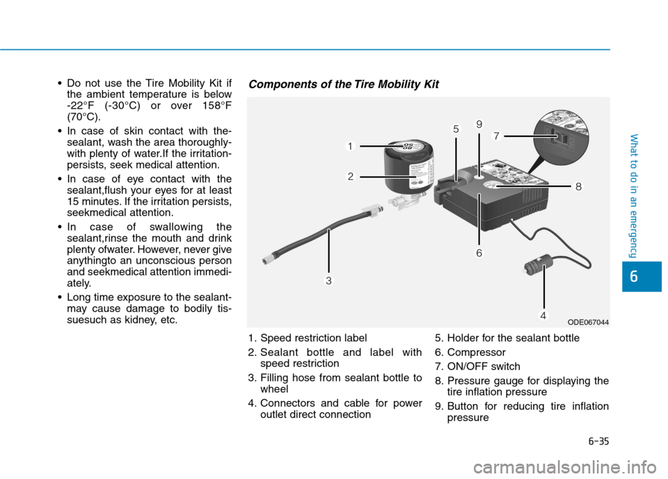
Components of the Tire Mobility Kit
ODE067044
1. Speed restriction label
2. Sealant bottle and label with
speed restriction
3. Filling hose from sealant bottle to
wheel
4. Connectors and cable for power
outlet direct connection5. Holder for the sealant bottle
6. Compressor
7. ON/OFF switch
8. Pressure gauge for displaying the
tire inflation pressure
9. Button for reducing tire inflation
pressure
Page 521 of 635
7-41
7
Maintenance
Wheel size designation
Wheels are also marked with impor-
tant information that you need if you
ever have to replace one. The follow-
ing explains what the letters and
numbers in the wheel size designa-
tion mean.
Example wheel size designation:
6.5J X 15
6.5 - Rim width in inches.
J - Rim contour designation.
15 - Rim diameter in inches.
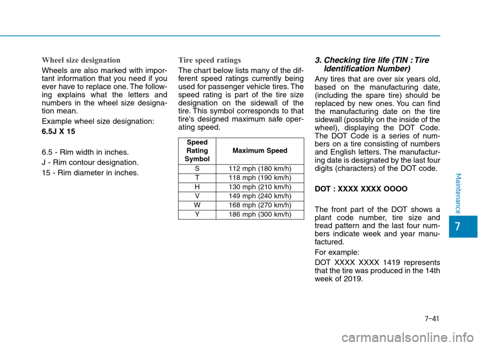
Tire speed ratings
The chart below lists many of the dif-
ferent speed ratings currently being
used for passenger vehicle tires. The
speed rating is part of the tire size
designation on the sidewall of the
tire. This symbol corresponds to that
tire's designed maximum safe oper-
ating speed.
3. Checking tire life (TIN : Tire
Identification Number)
Any tires that are over six years old,
based on the manufacturing date,
(including the spare tire) should be
replaced by new ones. You can find
the manufacturing date on the tire
sidewall (possibly on the inside of the
wheel), displaying the DOT Code.
The DOT Code is a series of num-
bers on a tire consisting of numbers
and English letters. The manufactur-
ing date is designated by the last four
digits (characters) of the DOT code.
DOT : XXXX XXXX OOOO
The front part of the DOT shows a
plant code number, tire size and
tread pattern and the last four num-
bers indicate week and year manu-
factured.
For example:
DOT XXXX XXXX 1419 represents
that the tire was produced in the 14th
week of 2019.
Speed
Rating
SymbolMaximum Speed
S 112 mph (180 km/h)
T 118 mph (190 km/h)
H 130 mph (210 km/h)
V 149 mph (240 km/h)
W 168 mph (270 km/h)
Y 186 mph (300 km/h)
Page 572 of 635
H Hy
yb
br
ri
id
d
S
Sy
ys
st
te
em
m
O
Ov
ve
er
rv
vi
ie
ew
w
HEV (Hybrid Electric Vehicle) System..................H2
Hybrid Vehicle ......................................................................H2
PHEV (Plug-In Electric Vehicle) System..............H3
Plug-in Hybrid Vehicle.......................................................H3
Charging the Plug-In Hybrid Vehicle....................H4
Charging Information .........................................................H4
Charging Types ....................................................................H4
Charging Time Information ...............................................H4
Charging Status ...................................................................H5
Charging Connector AUTO / LOCK Mode.....................H6
Scheduled Charging ............................................................H7
Charging Precautions .........................................................H8
AC Charge .............................................................................H9
Trickle Charge ....................................................................H15
Action to be taken when charging stops abruptly...H27
Driving the Hybrid/Plug-In Hybrid Vehicle .......H28
Starting the Vehicle ..........................................................H28
Special Features ................................................................H29
Hybrid System Gauge ......................................................H31
Plug-in Hybrid Mode (Plug-in hybrid vehicle)..........H32
Aux. Battery Saver+ (Plug-in hybrid vehicle) ...........H33
Warning and Indicator Lights ........................................H35
LCD Display Messages.....................................................H36
Energy flow ........................................................................H45
Safety Precautions For Hybrid System .............H49
High Voltage Battery System.........................................H49
Safety Plug .........................................................................H52
High Voltage Battery Cooling Duct ..............................H53
If an Accident Occurs ......................................................H54
When the Hybrid Vehicle Shuts Off ............................H55
Page 583 of 635
H12
Information
• Even though charging is possible
with the Engine Start/Stop button in
the ON/START position, for your
safety, start charging when the
Engine Start/Stop button is in the
OFF position and the vehicle shifted
to P (Park). After charging has
started, you can use electrical com-
ponents such as the radio by press-
ing the Engine Start/Stop button to
the ACC or ON position.
• During AC charging, the radio
reception may be bad.
• Moving the shift lever from P (Park)
to R (Reverse)/N (Neutral)/D
(Drive) stops the charging process.
To restart the charging process,
move the shift lever to P (Park),
place the Engine Start/Stop button
to the OFF position, and disconnect
the charging cable. Then, connect
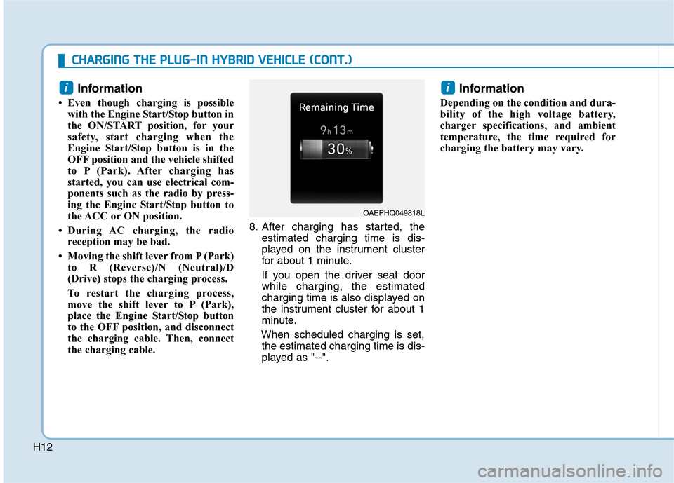
the charging cable.8. After charging has started, the
estimated charging time is dis-
played on the instrument cluster
for about 1 minute.
If you open the driver seat door
while charging, the estimated
charging time is also displayed on
the instrument cluster for about 1
minute.
When scheduled charging is set,
the estimated charging time is dis-
played as "--".
Information
Depending on the condition and dura-
bility of the high voltage battery,
charger specifications, and ambient
temperature, the time required for
charging the battery may vary.
ii
OAEPHQ049818L
C CH
HA
AR
RG
GI
IN
NG
G
T
TH
HE
E
P
PL
LU
UG
G-
-I
IN
N
H
HY
YB
BR
RI
ID
D
V
VE
EH
HI
IC
CL
LE
E
(
(C
CO
ON
NT
T.
.)
)
Page 587 of 635
H16
How to set the charge level of
the portable charger
1. Check the rated current of the
electric outlet prior to connecting
the plug to the outlet.
2. Connect the plug to a household
electric outlet.
3. Check the display window on the
control box.4. Press the button (1) on the back of
the control box for more than 1
second to adjust the charge level.
(Refer to charging cable type and
example for setting the charge
level.)
5. The display window on the control
box changes from 12A and 10A to
8A every time you press the but-
ton (1).6. When setting the charge level is
complete, start charging accord-
ing to the trickle charge proce-
dure.
OOSEVQ018054
C CH
HA
AR
RG
GI
IN
NG
G
T
TH
HE
E
P
PL
LU
UG
G-
-I
IN
N
H
HY
YB
BR
RI
ID
D
V
VE
EH
HI
IC
CL
LE
E
(
(C
CO
ON
NT
T.
.)
)
OAEE046506N
PlugElectric Outlet