Page 548 of 613
7-30
Maintenance
Type A
1. Raise the wiper arm and turn the
wiper blade assembly to expose
the plastic locking clip.
2. Press the clip and slide the blade
assembly downward.
3. Lift it off the arm.
4. Install the blade assembly in the
reverse order of removal.
Type B
1. Raise the wiper arm.
OLMB073020/H
OLMB073021R
OLMB073022/H
OLF074017/H
Page 549 of 613
7-31
7
Maintenance
2. Lift up the wiper blade clip (1).
Then lift up the wiper blade (2).3. Whilst pushing the lock (3), pull
down the wiper blade (4).4. Remove the wiper blade from the
wiper arm (5).
5. Install a new wiper blade assem-
bly in the reverse order of removal.
6. Return the wiper arm on the wind-
screen.
OAD075074ROAD075075ROAD075076R
Page 553 of 613
7-35
7
Maintenance
By jump starting
After a jump start from a good bat-
tery, drive the vehicle for 20-30 min-
utes before it is shutoff. The vehicle
may not restart if you shut it off
before the battery had a chance to
adequately recharge. See “Jump
Starting” in chapter 6 for more infor-
mation on jump starting procedures.
Information
An inappropriately disposed
battery can be harmful to
the environment and human
health. Dispose of the bat-
tery according to your local
law(s) or regulations.
Reset features
The following items need to be reset
after the battery has been dis-
charged or the battery has been dis-
connected.
See chapter 3 or 4 for:
Power Windows
Trip Computer
Climate Control System
Clock
Audio System
Sunroof
Driver Position Memory System
i
(Continued)
Watch the battery during
charging, and stop or reduce
the charging rate if the battery
cells begin boiling violently.
The negative battery cable
must be removed first and
installed last when the battery
is disconnected. Disconnect
the battery charger in the fol-
lowing order:
(1) Turn off the battery charger
main switch.
(2) Unhook the negative
clamp from the negative
battery terminal.
(3) Unhook the positive clamp
from the positive battery
terminal.
Always use a genuine HYUNDAI
approved battery when you
replace the battery.
Page 554 of 613
7-36
Maintenance
T TY
YR
RE
ES
S
A
AN
ND
D
W
WH
HE
EE
EL
LS
S
Tyre care
For proper maintenance, safety, and
maximum fuel economy, you must
always maintain recommended tyre
inflation pressures and stay within the
load limits and weight distribution rec-
ommended for your vehicle. (Continued)Replace tyres that are worn,
show uneven wear, or are dam-
aged. Worn tyres can cause
loss of braking effectiveness,
steering control, or traction.
ALWAYS replace tyres with
the same size as each tyre
that was originally supplied
with this vehicle. Using tyres
and wheels other than the rec-
ommended sizes could cause
unusual handling characteris-
tics, poor vehicle control, or
negatively affect your vehi-
cle’s Anti-Lock Brake System
(ABS) resulting in a serious
accident.
Tyre failure may cause loss of
vehicle control resulting in an
accident. To reduce risk of
SERIOUS INJURY or DEATH,
take the following precautions:
Inspect your tyres monthly for
proper inflation as well as
wear and damage.
The recommended cold tyre
pressure for your vehicle can
be found in this manual and on
the tyre label located on the
driver’s side centre pillar.
Always use a tyre pressure
gauge to measure tyre pres-
sure. Tyres with too much or
too little pressure wear
unevenly causing poor han-
dling.
Check the pressure of the
spare every time you check
the pressure of the other tyres
on your vehicle.
(Continued)
WARNING
Page 558 of 613
7-40
Maintenance
Wheel alignment and tyre bal-
ance
The wheels on your vehicle were
aligned and balanced carefully at the
factory to give you the longest tyre
life and best overall performance.
In most cases, you will not need to
have your wheels aligned again.
However, if you notice unusual tyre
wear or your vehicle pulling one way
or the other, the alignment may need
to be reset.
If you notice your vehicle vibrating
when driving on a smooth road, your
wheels may need to be rebalanced.
Incorrect wheel weights can dam-
age your vehicle’s aluminium
wheels. Use only approved wheel
weights.
Tyre replacement
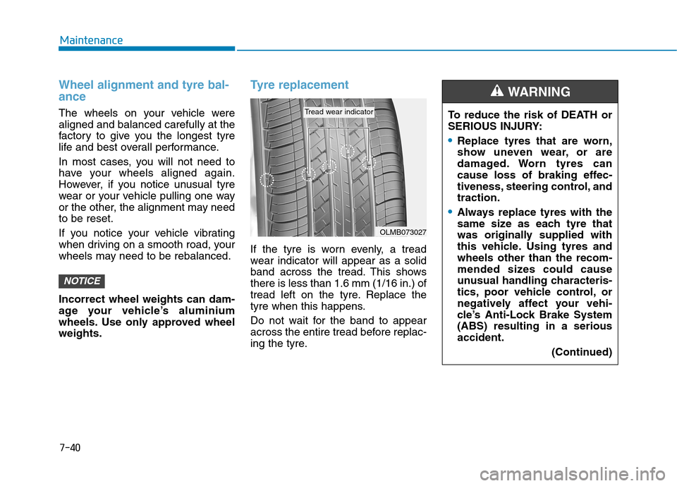
If the tyre is worn evenly, a tread
wear indicator will appear as a solid
band across the tread. This shows
there is less than 1.6 mm (1/16 in.) of
tread left on the tyre. Replace the
tyre when this happens.
Do not wait for the band to appear
across the entire tread before replac-
ing the tyre.
NOTICE
OLMB073027
Tread wear indicatorTo reduce the risk of DEATH or
SERIOUS INJURY:
Replace tyres that are worn,
show uneven wear, or are
damaged. Worn tyres can
cause loss of braking effec-
tiveness, steering control, and
traction.
Always replace tyres with the
same size as each tyre that
was originally supplied with
this vehicle. Using tyres and
wheels other than the recom-
mended sizes could cause
unusual handling characteris-
tics, poor vehicle control, or
negatively affect your vehi-
cle’s Anti-Lock Brake System
(ABS) resulting in a serious
accident.
(Continued)
WARNING
Page 567 of 613
7-49
7
Maintenance
Fuse switch
Always, place the fuse switch to the
ON position.
If you move the switch to the OFF
position, some items such as the
audio system and digital clock must
be reset and the smart key may not
work properly.
Information
If the fuse switch is OFF, “Turn on
FUSE SWITCH” message will appear.
Always place the fuse switch in
the ON position whilst driving
the vehicle.
Do not move the transportation
fuse switch repeatedly. The fuse
switch may be damaged.
Engine compartment panel
fuse replacement
1. Turn the vehicle off.
2. Turn all other switches off.
3. Remove the fuse panel cover by
pressing the tap and pulling up.
NOTICE
i
OAEPH078023
OAEPH078024
■Blade type fuse
■Cartridge type fuseOAE076019ROIK05165L
Page 570 of 613
7-52
Maintenance
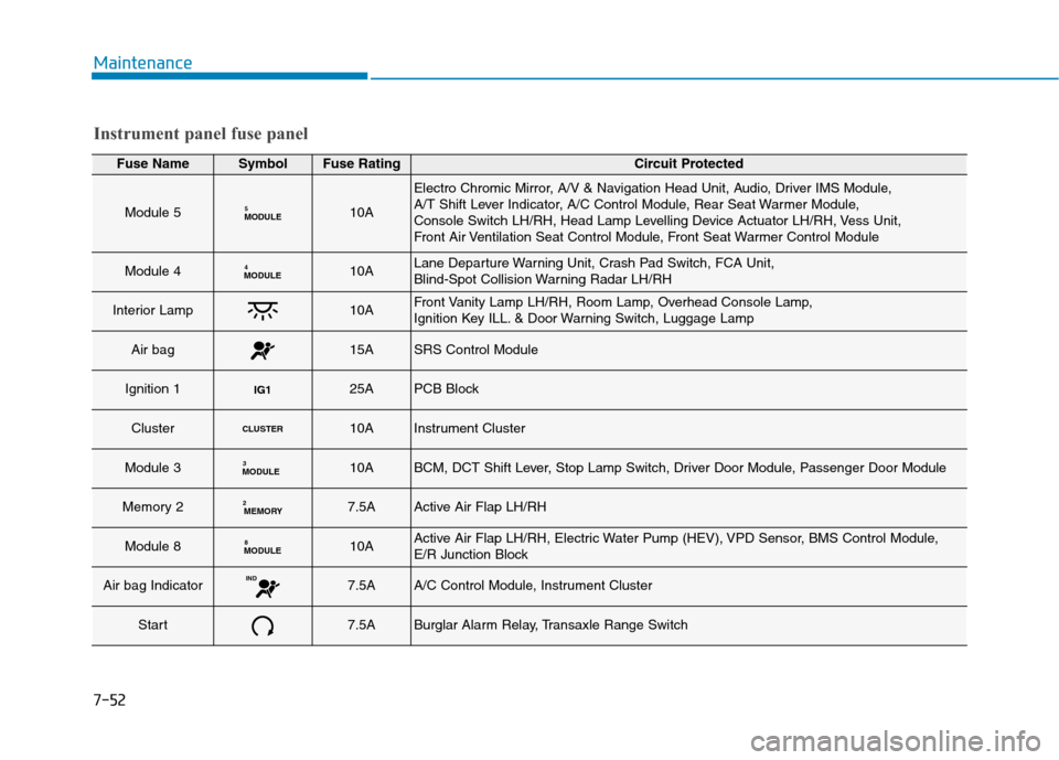
Instrument panel fuse panel
Fuse NameSymbolFuse RatingCircuit Protected
Module 5MODULE510A
Electro Chromic Mirror, A/V & Navigation Head Unit, Audio, Driver IMS Module,
A/T Shift Lever Indicator, A/C Control Module, Rear Seat Warmer Module,
Console Switch LH/RH, Head Lamp Levelling Device Actuator LH/RH, Vess Unit,
Front Air Ventilation Seat Control Module, Front Seat Warmer Control Module
Module 4MODULE410ALane Departure Warning Unit, Crash Pad Switch, FCA Unit,
Blind-Spot Collision Warning Radar LH/RH
Interior Lamp10AFront Vanity Lamp LH/RH, Room Lamp, Overhead Console Lamp,
Ignition Key ILL. & Door Warning Switch, Luggage Lamp
Air bag15ASRS Control Module
Ignition 1IG125APCB Block
ClusterCLUSTER10AInstrument Cluster
Module 3MODULE310ABCM, DCT Shift Lever, Stop Lamp Switch, Driver Door Module, Passenger Door Module
Memory 2MEMORY27.5AActive Air Flap LH/RH
Module 8MODULE810AActive Air Flap LH/RH, Electric Water Pump (HEV), VPD Sensor, BMS Control Module,
E/R Junction Block
Air bag IndicatorIND7.5AA/C Control Module, Instrument Cluster
Start7.5ABurglar Alarm Relay, Transaxle Range Switch
Page 571 of 613
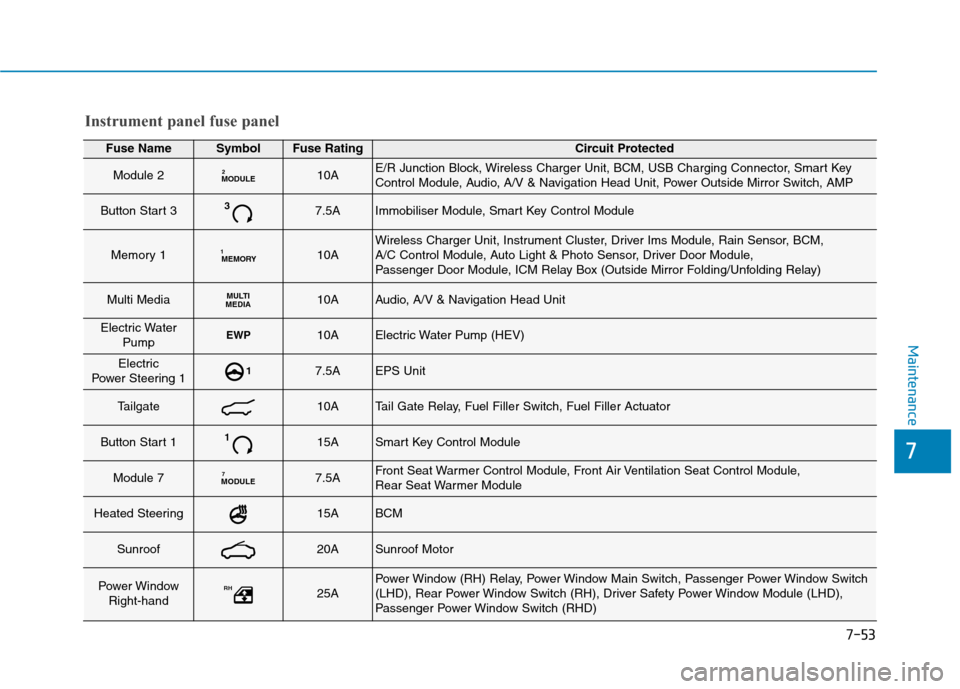
7-53
7
Maintenance
Fuse NameSymbolFuse RatingCircuit Protected
Module 2MODULE210AE/R Junction Block, Wireless Charger Unit, BCM, USB Charging Connector, Smart Key
Control Module, Audio, A/V & Navigation Head Unit, Power Outside Mirror Switch, AMP
Button Start 337.5AImmobiliser Module, Smart Key Control Module
Memory 1MEMORY110AWireless Charger Unit, Instrument Cluster, Driver Ims Module, Rain Sensor, BCM,
A/C Control Module, Auto Light & Photo Sensor, Driver Door Module,
Passenger Door Module, ICM Relay Box (Outside Mirror Folding/Unfolding Relay)
Multi MediaMULTI
MEDIA10AAudio, A/V & Navigation Head Unit
Electric Water
PumpEWP10AElectric Water Pump (HEV)
Electric
Power Steering 117.5AEPS Unit
Tailgate10ATail Gate Relay, Fuel Filler Switch, Fuel Filler Actuator
Button Start 1115ASmart Key Control Module
Module 7MODULE77.5AFront Seat Warmer Control Module, Front Air Ventilation Seat Control Module,
Rear Seat Warmer Module
Heated Steering15ABCM
Sunroof20ASunroof Motor
Power Window
Right-handRH25APower Window (RH) Relay, Power Window Main Switch, Passenger Power Window Switch
(LHD), Rear Power Window Switch (RH), Driver Safety Power Window Module (LHD),
Passenger Power Window Switch (RHD)
Instrument panel fuse panel