2020 DODGE CHARGER ignition
[x] Cancel search: ignitionPage 232 of 412
230IN CASE OF EMERGENCY
JACK LOCATION/SPARE TIRE STOWAGE
The jack and spare tire are both stowed under
an access cover in the trunk. Follow these steps
to access the jack and spare tire.
NOTE:
The spare tire must be removed in order to
access the jack.
1. Open the trunk.
2. Lift the access cover using the pull strap.
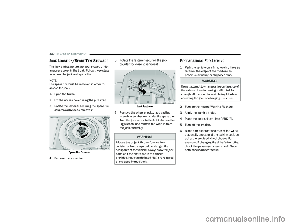
3. Rotate the fastener securing the spare tire
counterclockwise to remove it.
Spare Tire Fastener
4. Remove the spare tire. 5. Rotate the fastener securing the jack
counterclockwise to remove it.
Jack Fastener
6. Remove the wheel chocks, jack and lug wrench assembly from under the spare tire.
Turn the jack screw to the left to loosen the
lug wrench, and remove the wrench from
the jack assembly.
PREPARATIONS FOR JACKING
1. Park the vehicle on a firm, level surface as far from the edge of the roadway as
possible. Avoid icy or slippery areas.
2. Turn on the Hazard Warning Flashers.
3. Apply the parking brake.
4. Place the gear selector into PARK (P).
5. Turn off the ignition.
6. Block both the front and rear of the wheel diagonally opposite of the jacking position
using the provided wheel chocks. For
example, if changing the driver’s front tire,
chock the passenger’s rear wheel. Place
both chocks under the tire.
WARNING!
A loose tire or jack thrown forward in a
collision or hard stop could endanger the
occupants of the vehicle. Always stow the jack
parts and the spare tire in the places
provided. Have the deflated (flat) tire repaired
or replaced immediately.
WARNING!
Do not attempt to change a tire on the side of
the vehicle close to moving traffic. Pull far
enough off the road to avoid being hit when
operating the jack or changing the wheel.
20_LD_OM_EN_USC_t.book Page 230
Page 239 of 412
IN CASE OF EMERGENCY237
SEALING A TIRE WITH TIRE SERVICE KIT
(A) Whenever You Stop To Use Tire Service
Kit:
1. Pull over to a safe location and turn on the
vehicle’s Hazard Warning flashers.
2. Verify that the valve stem (on the wheel with the deflated tire) is in a position that is near
to the ground. This will allow the Tire Service
Kit Hoses (6) and (7) to reach the valve
stem and keep the Tire Service Kit flat on
the ground. This will provide the best
positioning of the kit when injecting the
sealant into the deflated tire and running
the air pump. Move the vehicle as
necessary to place the valve stem in this
position before proceeding.
3. Place the transmission in PARK (auto transmission) or in Gear (manual
transmission) and place the ignition in the
OFF position.
4. Apply the parking brake.
(B) Setting Up To Use Tire Service Kit:
1. Push in the Mode Select Knob (5) and turn to the Sealant Mode position.
2. Uncoil the Sealant Hose (6) and then
remove the cap from the fitting at the end of
the hose.
3. Place the Tire Service Kit flat on the ground next to the deflated tire.
4. Remove the cap from the valve stem and then screw the fitting at the end of the
Sealant Hose (6) onto the valve stem.
5. Uncoil the Power Plug (8) and insert the plug into the vehicle’s 12 Volt power outlet.
NOTE:
Do not remove foreign objects (e.g., screws or
nails) from the tire.
(C) Injecting Tire Service Kit Sealant Into
The Deflated Tire:
Always start the engine before turning ON the
Tire Service Kit.
NOTE:
Manual transmission vehicles must have the
parking brake engaged and the gear selector in
NEUTRAL.
After pushing the Power Button (4), the
sealant (white fluid) will flow from the Sealant
Bottle (1) through the Sealant Hose (6) and
into the tire.
NOTE:
Sealant may leak out through the puncture in
the tire.
If the sealant (white fluid) does not flow within 0
– 10 seconds through the Sealant Hose (6):
1. Push the Power Button (4) to turn Off the Tire Service Kit. Disconnect the Sealant
Hose (6) from the valve stem. Make sure
the valve stem is free of debris. Reconnect
the Sealant Hose (6) to the valve stem.
Check that the Mode Select Knob (5) is in
the Sealant Mode position and not Air
Mode. Push the Power Button (4) to turn
On the Tire Service Kit.
2. Connect the Power Plug (8) to a different 12 Volt power outlet in your vehicle or
another vehicle, if available. Make sure the
engine is running before turning ON the
Tire Service Kit.
6
20_LD_OM_EN_USC_t.book Page 237
Page 242 of 412

240IN CASE OF EMERGENCY
(Continued)
JUMP STARTING
If your vehicle has a discharged battery, it can
be jump started using a set of jumper cables
and a battery in another vehicle, or by using a
portable battery booster pack. Jump starting
can be dangerous if done improperly, so please
follow the procedures in this section carefully.
NOTE:
When using a portable battery booster pack,
follow the manufacturer's operating instruc-
tions and precautions.
PREPARATIONS FOR JUMP START
The battery is stored under an access cover in
the trunk. Remote battery posts are located on
the right side of the engine compartment for
jump starting.
Jump Starting Locations
NOTE:
The remote battery posts are viewed by
standing on the right side of the vehicle looking
over the fender.
Jump Starting Locations
WARNING!
Do not attempt jump starting if the battery is
frozen. It could rupture or explode and cause
personal injury.
CAUTION!
Do not use a portable battery booster pack or
any other booster source with a system
voltage greater than 12 Volts or damage to
the battery, starter motor, alternator or
electrical system may occur.
(+) — Remote Positive Post
(-) — Remote Negative Post
WARNING!
Take care to avoid the radiator cooling fan
whenever the hood is raised. It can start
anytime the ignition switch is ON. You can
be injured by moving fan blades.
Remove any metal jewelry such as rings,
watch bands and bracelets that could
make an inadvertent electrical contact. You
could be seriously injured.
20_LD_OM_EN_USC_t.book Page 240
Page 243 of 412

IN CASE OF EMERGENCY241
1. Apply the parking brake, shift the
automatic transmission into PARK and
place the ignition in the OFF position.
2. Turn off the heater, radio, and all unnecessary electrical accessories.
3. If using another vehicle to jump start the battery, park the vehicle within the jumper
cable’s reach, apply the parking brake and
make sure the ignition is OFF.
JUMP STARTING PROCEDURE
1. Connect the positive
(+) end of the jumper
cable to the remote positive (+)
post of the
vehicle with the discharged battery.
2. Connect the opposite end of the positive (+)
jumper cable to the positive (+) post of the
booster battery.
3. Connect the negative (-) end of the jumper
cable to the negative (-) post of the booster
battery.
4. Connect the opposite end of the negative (-)
jumper cable to the remote negative (-) post
of the vehicle with the discharged battery. 5. Start the engine in the vehicle that has the
booster battery, let the engine idle a few
minutes, and then start the engine in the
vehicle with the discharged battery.
6. Once the engine is started, remove the jumper cables in the reverse sequence.
Disconnecting The Jumper Cables
1. Disconnect the negative
(-) end of the
jumper cable from the remote negative (-)
post of the vehicle with the discharged
battery.
2. Disconnect the opposite end of the negative (-) jumper cable from the negative (-) post of
the booster battery.
Batteries contain sulfuric acid that can
burn your skin or eyes and generate
hydrogen gas which is flammable and
explosive. Keep open flames or sparks
away from the battery.
WARNING!
Do not allow vehicles to touch each other as
this could establish a ground connection and
personal injury could result.
WARNING! (Continued)
WARNING!
Failure to follow this jump starting procedure
could result in personal injury or property
damage due to battery explosion.
CAUTION!
Failure to follow these procedures could
result in damage to the charging system of
the booster vehicle or the discharged vehicle.
WARNING!
Do not connect the jumper cable to the
negative (-) post of the discharged battery. The
resulting electrical spark could cause the
battery to explode and could result in personal
injury. Only use the specific ground point, do
not use any other exposed metal parts.
6
20_LD_OM_EN_USC_t.book Page 241
Page 248 of 412

246IN CASE OF EMERGENCY
SRT — TOWING A DISABLED VEHICLE
This section describes procedures for towing a disabled vehicle using a commercial towing service.
Proper towing or lifting equipment is required to
prevent damage to your vehicle. Use only tow
bars and other equipment designed for this
purpose, following equipment manufacturer’s
instructions. Use of safety chains is mandatory.
Attach a tow bar or other towing device to main
structural members of the vehicle, not to
bumpers or associated brackets. State and
local laws regarding vehicles under tow must be
observed. If you must use the accessories (wipers,
defrosters, etc.) while being towed, the ignition
must be in the ON/RUN mode, not the ACC
mode.
If the key fob is unavailable, or the vehicle's
battery is discharged, refer to "Manual Park
Release" in this section for instructions on
shifting the transmission out of PARK for
towing.
Towing Condition
Wheels OFF The GroundAutomatic Transmission
Flat Tow NONEIf transmission is operable:
• Transmission in
NEUTRAL
• 30 mph (48 km/h) max speed
• 30 miles (48 km) max distance
Wheel Lift Or Dolly Tow Front
NOT ALLOWED
Rear NOT RECOMMENDED
Flatbed ALLBEST METHOD
CAUTION!
DO NOT use sling-type equipment when
towing. Vehicle damage may occur.
When securing the vehicle to a flatbed
truck, do not attach to front or rear suspen-
sion components. Damage to your vehicle
may result from improper towing.
The manufacturer does not recommend
towing this vehicle using a tow dolly.
Vehicle damage may occur.
20_LD_OM_EN_USC_t.book Page 246
Page 250 of 412
248IN CASE OF EMERGENCY
(Continued)
NON SRT — TOWING A DISABLED VEHICLE
This section describes procedures for towing a disabled vehicle using a commercial towing service.
Proper towing or lifting equipment is required to
prevent damage to your vehicle. Use only tow
bars and other equipment designed for this
purpose, following equipment manufacturer’s
instructions. Use of safety chains is mandatory.
Attach a tow bar or other towing device to main
structural members of the vehicle, not to
bumpers or associated brackets. State and
local laws regarding vehicles under tow must be
observed.If you must use the accessories (wipers,
defrosters, etc.) while being towed, the ignition
must be in the ON/RUN mode, not the ACC
mode.
If the key fob is unavailable, or the vehicle's
battery is discharged, refer to "Manual Park
Release" in this section for instructions on
shifting the transmission out of PARK for
towing.
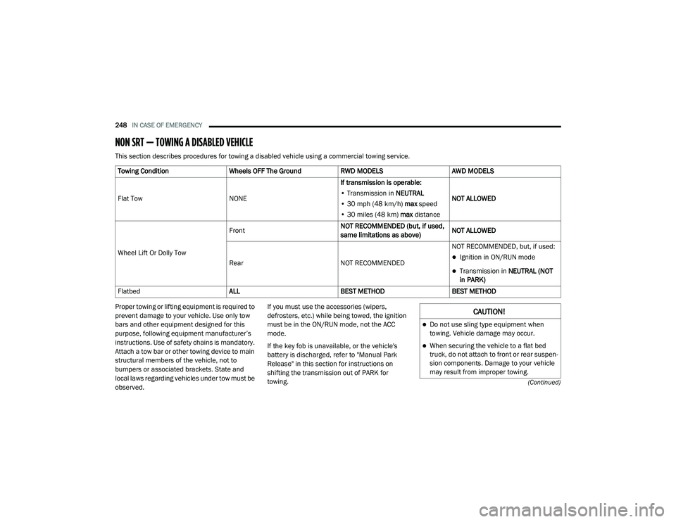
Towing Condition
Wheels OFF The GroundRWD MODELSAWD MODELS
Flat Tow NONEIf transmission is operable:
• Transmission in NEUTRAL
• 30 mph (48 km/h) max speed
• 30 miles (48 km) max distance NOT ALLOWED
Wheel Lift Or Dolly Tow Front
NOT RECOMMENDED (but, if used,
same limitations as above)NOT ALLOWED
Rear NOT RECOMMENDEDNOT RECOMMENDED, but, if used:
Ignition in ON/RUN mode
Transmission in
NEUTRAL (NOT
in PARK)
Flatbed ALLBEST METHODBEST METHOD
CAUTION!
Do not use sling type equipment when
towing. Vehicle damage may occur.
When securing the vehicle to a flat bed
truck, do not attach to front or rear suspen -
sion components. Damage to your vehicle
may result from improper towing.
20_LD_OM_EN_USC_t.book Page 248
Page 251 of 412
IN CASE OF EMERGENCY249
(Continued)
ALL WHEEL DRIVE (AWD) MODELS
The manufacturer recommends towing your
vehicle with all four wheels OFF the ground
using a flatbed.
If the transmission and driveline are operable,
AWD models can also be towed with the ignition
in the ON/RUN mode, the transmission in
NEUTRAL (not in PARK!), and the rear wheels
OFF the ground with no limitation on speed or
distance. Since the ignition MUST be in the ON/
RUN mode to tow in this manner, AWD vehicles
must be towed with ALL FOUR wheels OFF the
ground (e.g. on a flatbed truck) if the key fob is
unavailable.
REAR-WHEEL DRIVE (RWD) MODELS
The manufacturer recommends towing your
vehicle with all four wheels OFF the ground
using a flatbed.
If flatbed equipment is not available, and the
transmission is operable, this vehicle may be
flat towed (with all four wheels on the ground)
under the following conditions:
The automatic transmission must be in
NEUTRAL. Refer to "Manual Park Release" in this
section for instructions on shifting the transmis -
sion to NEUTRAL when the engine is off.
The towing speed must not exceed 30 mph
(48 km/h).
The towing distance must not exceed
30 miles (48 km).
If the transmission is not operable, or the
vehicle must be towed faster than 30 mph
(48 km/h) or farther than 30 miles (48 km),
then the only acceptable method of towing is
with a flatbed truck.
ENHANCED ACCIDENT RESPONSE SYSTEM
(EARS)
This vehicle is equipped with an Enhanced
Accident Response System.
Please refer to “Occupant Restraint Systems” in
“Safety” for further information on the Enhanced
Accident Response System (EARS) function.
EVENT DATA RECORDER (EDR)
This vehicle is equipped with an Event Data
Recorder (EDR). The main purpose of an EDR is
to record data that will assist in understanding
how a vehicle’s systems performed under
certain crash or near crash-like situations, such
as an air bag deployment or hitting a road
obstacle.
Please refer to “Occupant Restraint Systems” in
“Safety” for further information on the Event
Data Recorder (EDR).
The manufacturer does not recommend
towing this vehicle using a tow dolly.
Vehicle damage may occur.
CAUTION!
Towing this vehicle using any other method
can cause severe transmission and/or
transfer case damage.
CAUTION! (Continued)
Damage from improper towing is not
covered under the New Vehicle Limited
Warranty.
CAUTION!CAUTION!
Towing this vehicle in violation of the above
requirements can cause severe transmission
damage. Damage from improper towing is not
covered under the New Vehicle Limited Warranty.
6
20_LD_OM_EN_USC_t.book Page 249
Page 278 of 412
276SERVICING AND MAINTENANCE
(Continued)
recommends that air conditioning service be
performed by an authorized dealer using
recovery and recycling equipment.
NOTE:
Use only manufacturer approved A/C system
PAG compressor oil, and refrigerants.
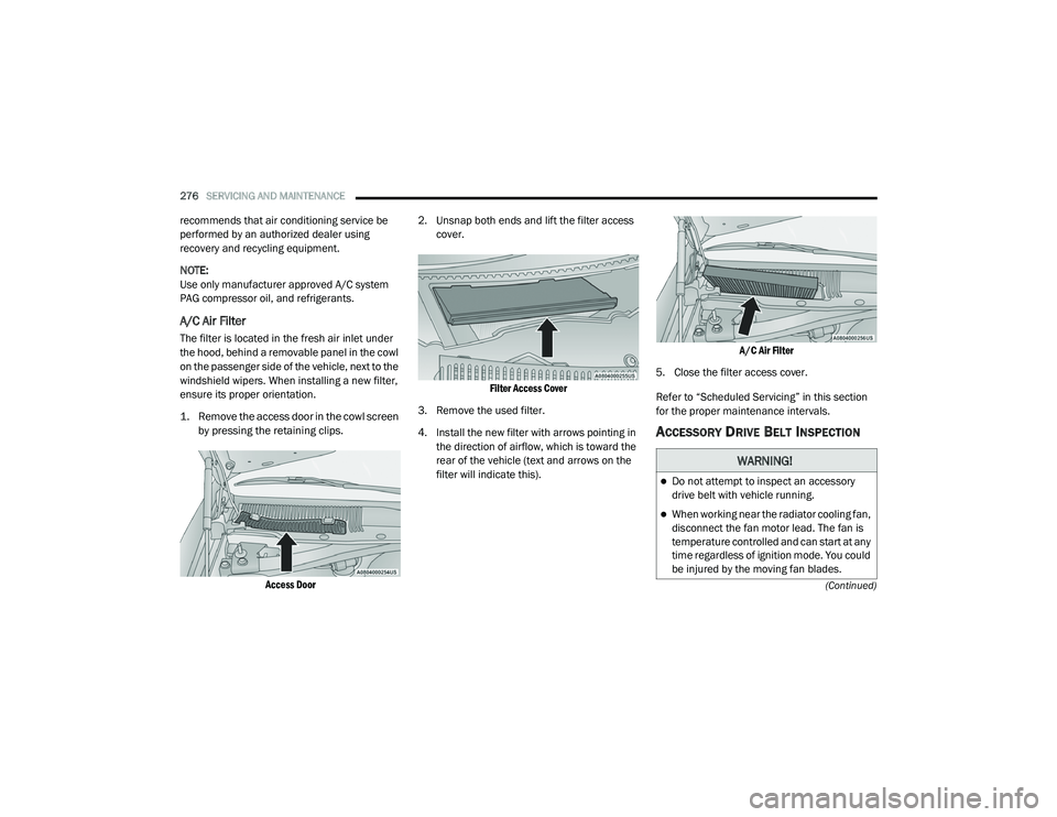
A/C Air Filter
The filter is located in the fresh air inlet under
the hood, behind a removable panel in the cowl
on the passenger side of the vehicle, next to the
windshield wipers. When installing a new filter,
ensure its proper orientation.
1. Remove the access door in the cowl screen by pressing the retaining clips.
Access Door
2. Unsnap both ends and lift the filter access
cover.
Filter Access Cover
3. Remove the used filter.
4. Install the new filter with arrows pointing in the direction of airflow, which is toward the
rear of the vehicle (text and arrows on the
filter will indicate this).
A/C Air Filter
5. Close the filter access cover.
Refer to “Scheduled Servicing” in this section
for the proper maintenance intervals.
ACCESSORY DRIVE BELT INSPECTION
WARNING!
Do not attempt to inspect an accessory
drive belt with vehicle running.
When working near the radiator cooling fan,
disconnect the fan motor lead. The fan is
temperature controlled and can start at any
time regardless of ignition mode. You could
be injured by the moving fan blades.
20_LD_OM_EN_USC_t.book Page 276