2020 CHRYSLER 300 reset
[x] Cancel search: resetPage 5 of 328

3
EXTERIOR LIGHTS ................................................42 Multifunction Lever ...................................... 42
Headlight Switch .......................................... 42
Daytime Running Lights (DRLs) .................. 43
High/Low Beam Switch ............................... 43
Automatic High Beam — If Equipped ......... 43
Flash-To-Pass ............................................... 44
Automatic Headlights ................................. 44
Parking Lights ............................................. 44
Headlights On With Wipers ......................... 44
Adaptive Bi-Xenon High Intensity
Discharge Headlights — If Equipped........... 44 Headlight Time Delay .................................. 45
Lights-On Reminder .................................... 45
Fog Lights — If Equipped ............................. 45
Turn Signals ................................................ 46
Lane Change Assist — If Equipped ............. 46
INTERIOR LIGHTS ................................................46
Courtesy Lights ............................................ 46
WINDSHIELD WIPERS AND WASHERS .............48
Wiper Operation ........................................... 48
Rain Sensing Wipers — If Equipped ........... 49
CLIMATE CONTROLS ...........................................50
Automatic Climate Control Overview .......... 50
Climate Control Functions ........................... 55
Automatic Temperature Control (ATC) ....... 55
Operating Tips ............................................. 56 WINDOWS ............................................................ 57
Power Window Controls .............................. 57
Wind Buffeting ............................................ 59
PANORAMIC SUNROOF — IF EQUIPPED ........... 59
Opening Sunroof .......................................... 59
Closing Sunroof............................................ 60
Wind Buffeting ............................................ 60
Opening Power Shade ................................. 60
Closing Power Shade................................... 61
Pinch Protect Feature.................................. 61
Sunroof Maintenance.................................. 61
Ignition Off Operation .................................. 61
HOOD ..................................................................... 61
To Open The Hood ...................................... 61
To Close The Hood ....................................... 62
TRUNK.................................................................... 62
Opening ........................................................ 62
Closing .......................................................... 63
Trunk Safety ................................................. 63
Cargo Area Features ................................... 64
LOAD LEVELING SYSTEM — IF EQUIPPED ....... 65
GARAGE DOOR OPENER — IF EQUIPPED ........ 66 Before You Begin Programming
HomeLink® .................................................. 66 Canadian/Gate Operator Programming ..... 68
Using HomeLink®........................................ 69
Security......................................................... 69
Troubleshooting Tips ................................... 69
General Information .................................... 70 INTERNAL EQUIPMENT ........................................70
Storage ......................................................... 70
Cupholders .................................................. 72
Power Sunshade — If Equipped .................. 73
Electrical Power Outlets .............................. 74
Sunglasses Bin Door .................................. 75
GETTING TO KNOW YOUR
INSTRUMENT PANEL
INSTRUMENT CLUSTER .......................................76
Instrument Cluster Descriptions ................ 77
INSTRUMENT CLUSTER DISPLAY .......................78
Location And Controls ................................. 78
Engine Oil Life Reset .................................. 79
Instrument Cluster Display Selectable
Menu Items .................................................. 80 Battery Saver On/Battery Saver Mode
Message — Electrical Load Reduction
Actions — If Equipped ................................. 83
WARNING LIGHTS AND MESSAGES ..................84
Red Warning Lights ..................................... 85
Yellow Warning Lights ................................. 88
Yellow Indicator Lights ................................ 91
Green Indicator Lights ................................. 91
White Indicator Lights ................................. 92
Blue Indicator Lights ................................... 92
ONBOARD DIAGNOSTIC SYSTEM — OBD II ......93
Onboard Diagnostic System (OBD II)
Cybersecurity ............................................... 93
20_LX_OM_EN_USC_t.book Page 3
Page 21 of 328

GETTING TO KNOW YOUR VEHICLE19
REMOTE START ABORT MESSAGE ON
T
HE INSTRUMENT CLUSTER DISPLAY —
I
F EQUIPPED
The following messages will display in the
instrument cluster display if the vehicle fails to
remote start or exits remote start prematurely:
Remote Start Aborted — Door Open
Remote Start Aborted — Hood Open
Remote Start Aborted — Fuel Low
Remote Start Aborted — Trunk Open
Remote Start Disabled — Start Vehicle To
Reset
Remote Start Aborted — Too Cold
Remote Start Aborted — Time Expired
The message will stay active until the ignition is
placed in the ON/RUN position.
TO ENTER REMOTE START MODE
Push and release the remote start button on the
key fob twice within five seconds. The vehicle
doors will lock, the parking lights will flash, and
the horn will chirp twice (if programmed). Then,
the engine will start, and the vehicle will remain
in the Remote Start mode for a 15 minute cycle.
NOTE:
If an engine fault is present or fuel level is
low, the vehicle will start and then shut down
in 10 seconds.
The park lamps will turn on and remain on
during Remote Start mode.
For security, power window and power
sunroof operation (if equipped) are disabled
when the vehicle is in the Remote Start
mode.
The engine can be started two consecutive
times with the key fob. However, the ignition
must be cycled by pushing the START/STOP
ignition button twice (or the ignition switch
must be placed in the ON/RUN position)
before you can repeat the start sequence for
a third cycle.
TO EXIT REMOTE START MODE
W
ITHOUT DRIVING THE VEHICLE
Push and release the remote start button one
time or allow the engine to run for the entire
15 minute cycle.
NOTE:
To avoid unintentional shutdowns, the system
will disable for two seconds after receiving a
valid remote start request.
TO EXIT REMOTE START MODE AND
D
RIVE THE VEHICLE
Before the end of 15 minute cycle, push and
release the unlock button on the key fob to
unlock the doors and disarm the vehicle
security alarm (if equipped). Then, prior to the
end of the 15 minute cycle, push and release
the START/STOP ignition button.
NOTE:
For vehicles not equipped with the Keyless
Enter-N-Go — Passive Entry feature, the igni -
tion switch must be in the ON/RUN position
in order to drive the vehicle.
Keep key fobs away from children. Opera -
tion of the Remote Start System, windows,
door locks or other controls could cause
serious injury or death.
WARNING! (Continued)
2
20_LX_OM_EN_USC_t.book Page 19
Page 30 of 328

28GETTING TO KNOW YOUR VEHICLE
AUTOMATIC DOOR LOCKS — IF
E
QUIPPED
The auto door lock feature default condition is
enabled. When enabled, the door locks will lock
automatically when the vehicle's speed exceeds
15 mph (24 km/h). The auto door lock feature
can be enabled or disabled by an authorized
dealer per written request of the customer.
Please see an authorized dealer for service.
CHILD-PROTECTION DOOR LOCK
S
YSTEM — REAR DOORS
To provide a safer environment for small
children riding in the rear seats, the rear doors
are equipped with Child-Protection Door Lock
system.
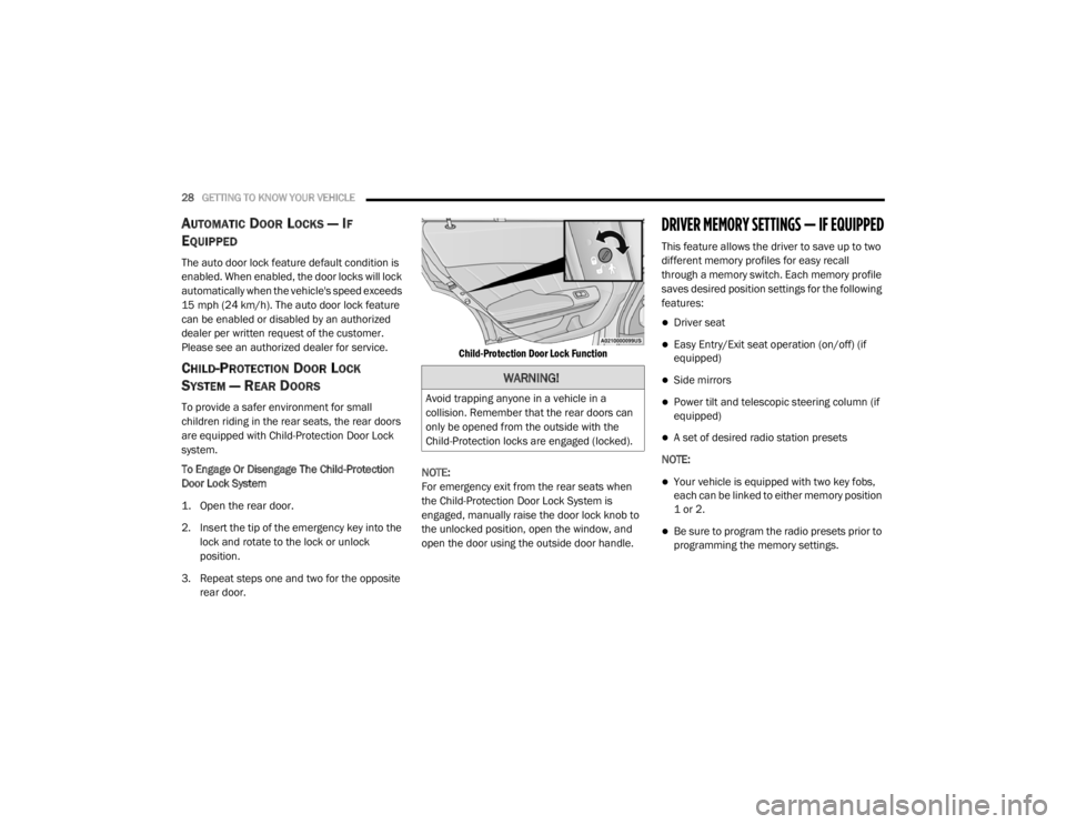
To Engage Or Disengage The Child-Protection
Door Lock System
1. Open the rear door.
2. Insert the tip of the emergency key into the
lock and rotate to the lock or unlock
position.
3. Repeat steps one and two for the opposite rear door.
Child-Protection Door Lock Function
NOTE:
For emergency exit from the rear seats when
the Child-Protection Door Lock System is
engaged, manually raise the door lock knob to
the unlocked position, open the window, and
open the door using the outside door handle.
DRIVER MEMORY SETTINGS — IF EQUIPPED
This feature allows the driver to save up to two
different memory profiles for easy recall
through a memory switch. Each memory profile
saves desired position settings for the following
features:
Driver seat
Easy Entry/Exit seat operation (on/off) (if
equipped)
Side mirrors
Power tilt and telescopic steering column (if
equipped)
A set of desired radio station presets
NOTE:
Your vehicle is equipped with two key fobs,
each can be linked to either memory position
1 or 2.
Be sure to program the radio presets prior to
programming the memory settings.
WARNING!
Avoid trapping anyone in a vehicle in a
collision. Remember that the rear doors can
only be opened from the outside with the
Child-Protection locks are engaged (locked).
20_LX_OM_EN_USC_t.book Page 28
Page 31 of 328

GETTING TO KNOW YOUR VEHICLE29
The memory settings switch is located on the
driver’s door trim panel. The switch consists of
three buttons:
The set (S) button, which is used to activate
the memory save function.
The (1) and (2) buttons which are used to
recall either of two pre-programmed memory
profiles.
Memory Settings Buttons
PROGRAMMING THE MEMORY FEATURE
To create a new memory profile, perform the
following:
NOTE:
Saving a new memory profile will erase the
selected profile from memory.
1. Place the vehicle’s ignition in the ON/RUN position (do not start the engine).
2. Adjust all memory profile settings to desired preferences (i.e., seat, side mirror, power tilt
and telescopic steering column [if
equipped], and radio station presets).
3. Push and release the set (S) button on the memory switch, and then push the desired
memory button (1 or 2) within five seconds.
The instrument cluster display will display
which memory position has been set.
NOTE:
Memory profiles can be set without the vehicle
in PARK, but the vehicle must be in PARK to
recall a memory profile.
LINKING AND UNLINKING THE REMOTE
K
EYLESS ENTRY KEY FOB TO MEMORY
Your key fobs can be programmed to recall one
of two saved memory profiles by pushing the
unlock button on the key fob.
NOTE:
Before programming your key fobs you must
select the “Personal Settings Linked To Key
Fob” feature through the Uconnect system
screen. Refer to “Uconnect Settings” in “Multi -
media” for further information.
To program your key fobs, perform the following:
1. Place the vehicle’s ignition in the OFF position.
2. Select a desired memory profile, 1 or 2.
3. Once the profile has been recalled, push and release the set (S) button on the
memory switch.
4. Within five seconds, push and release button (1) or (2) accordingly. “Memory
Profile Set” (1 or 2) will display in the
instrument cluster.
2
20_LX_OM_EN_USC_t.book Page 29
Page 43 of 328

GETTING TO KNOW YOUR VEHICLE41
If the mirror does not electrically fold, check for
ice or dirt build up at the pivot area which can
cause excessive drag.
Power Folding Mirror Switch
Automatic Folding Mirrors
When the Automatic Folding Mirrors feature is
enabled, the exterior mirrors will fold in when
exiting the vehicle (with the ignition OFF, all
doors closed, and the doors are locked).
If the exterior mirrors were auto-folded, they
will unfold when the ignition is placed in the
ON position.
If the exterior mirrors were manually folded,
they will not automatically unfold. NOTE:
The Automatic Fold/Unfold Mirrors feature is
not turned on when delivered from the factory.
The Automatic Fold/Unfold Mirrors feature can
be turned on and off using the Uconnect
System. Refer to “Uconnect Settings” in "Multi
-
media" for further information.
Resetting The Power Folding Outside Mirrors
You may need to reset the power folding mirrors
if the following occurs:
The mirrors are accidentally blocked while
folding.
The mirrors are accidentally manually
folded/unfolded.
The mirrors come out of the unfolded posi -
tion.
The mirrors shake and vibrate at normal
driving speeds.
To reset the power folding mirrors, fold and
unfold them by pushing the button (this may
require multiple button pushes). This resets
them to their normal position.
HEATED MIRRORS — IF EQUIPPED
These mirrors are heated to melt frost
or ice. This feature will be activated
whenever you turn on the rear window
defroster (if equipped). Refer to “Climate
Controls” in this chapter for further information.
TILT SIDE MIRRORS IN REVERSE — IF
E
QUIPPED
Tilt Side Mirrors In Reverse provides automatic
outside mirror positioning which will aid the
driver’s view of the ground rearward of the front
doors. The outside mirrors will move slightly
downward from the present position when the
vehicle is shifted into REVERSE. The outside
mirrors will then return to the original position
when the vehicle is shifted out of the REVERSE
position. Each stored memory setting will have
an associated Tilt Side Mirrors In Reverse
position.
NOTE:
The Tilt Side Mirrors In Reverse feature is not
turned on when delivered from the factory. The
Tilt Side Mirrors In Reverse feature can be
turned on and off using the Uconnect system.
Refer to “Uconnect Settings” in “Multimedia”
for further information.
2
20_LX_OM_EN_USC_t.book Page 41
Page 60 of 328

58GETTING TO KNOW YOUR VEHICLE
Auto-Down Feature
The driver and, in some models, passenger
power window switches have an Auto-Down
feature. Push the window switch to the second
detent, release, and the window will go down
automatically.
To open the window part way, push the window
switch to the first detent and release it when
you want the window to stop.
To stop the window from going all the way down
during the Auto-Down operation, pull up on the
switch briefly.
Auto-Up Feature With Anti-Pinch Protection
— If Equipped
Pull window up switch to second detent for at
least a half of a second and the window will go
up automatically.
To stop the window during an Auto-Up
operation, push or pull the window switch again.
To close the window part way, pull and hold the
window switch briefly and release it when you
want the window to stop. NOTE:
If the window runs into any obstacle during
Auto-Closure, it will reverse direction and
then go back down. Remove the obstacle and
use the window switch again to close the
window.
Any impact due to rough road conditions may
trigger the Auto-Reverse function unexpect
-
edly during auto-closure. If this happens, pull
and hold the switch to close the window
manually.
Reset Auto-Up
Should the Auto-Up feature stop working, the
window may need to be reset. To reset Auto-Up:
1. Make sure the door is fully closed.
2. Pull the window switch up to close the
window completely and continue to hold the
switch up for an additional two seconds
after the window is closed. 3. Push the window switch down firmly to the
second detent to open the window
completely and continue to hold the switch
down for an additional two seconds after
the window is fully open.
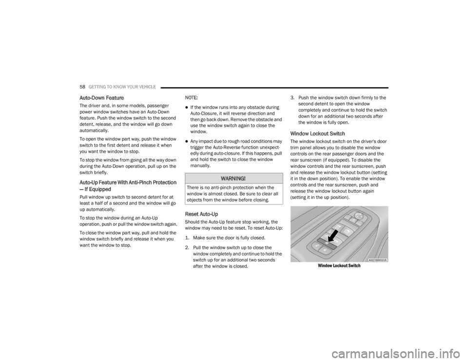
Window Lockout Switch
The window lockout switch on the driver's door
trim panel allows you to disable the window
controls on the rear passenger doors and the
rear sunscreen (if equipped). To disable the
window controls and the rear sunscreen, push
and release the window lockout button (setting
it in the down position). To enable the window
controls and the rear sunscreen, push and
release the window lockout button again
(setting it in the up position).
Window Lockout Switch
WARNING!
There is no anti-pinch protection when the
window is almost closed. Be sure to clear all
objects from the window before closing.
20_LX_OM_EN_USC_t.book Page 58
Page 67 of 328

GETTING TO KNOW YOUR VEHICLE65
Grocery Bag Hooks
The rear cargo area is equipped with grocery
bag hooks, located on either side of the rear
cargo area.
Grocery Bag Hooks
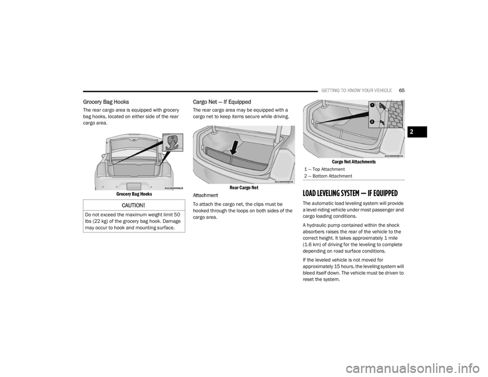
Cargo Net — If Equipped
The rear cargo area may be equipped with a
cargo net to keep items secure while driving.
Rear Cargo Net
Attachment
To attach the cargo net, the clips must be
hooked through the loops on both sides of the
cargo area.
Cargo Net Attachments
LOAD LEVELING SYSTEM — IF EQUIPPED
The automatic load leveling system will provide
a level-riding vehicle under most passenger and
cargo loading conditions.
A hydraulic pump contained within the shock
absorbers raises the rear of the vehicle to the
correct height. It takes approximately 1 mile
(1.6 km) of driving for the leveling to complete
depending on road surface conditions.
If the leveled vehicle is not moved for
approximately 15 hours, the leveling system will
bleed itself down. The vehicle must be driven to
reset the system.CAUTION!
Do not exceed the maximum weight limit 50
lbs (22 kg) of the grocery bag hook. Damage
may occur to hook and mounting surface.
1 — Top Attachment
2 — Bottom Attachment
2
20_LX_OM_EN_USC_t.book Page 65
Page 81 of 328

GETTING TO KNOW YOUR INSTRUMENT PANEL79
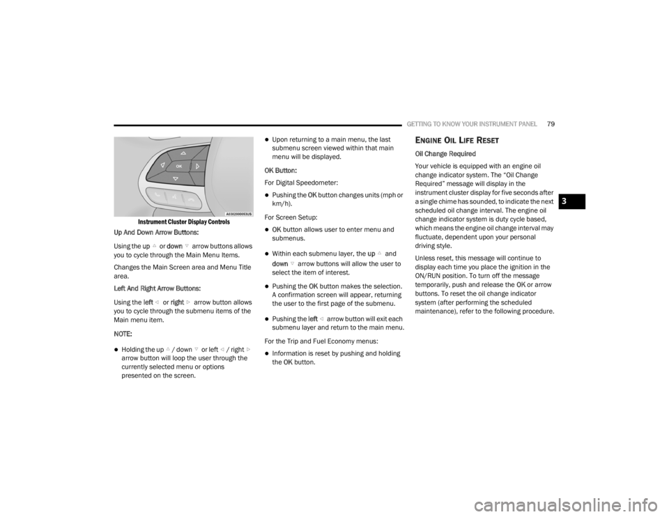
Instrument Cluster Display Controls
Up And Down Arrow Buttons:
Using the up or down arrow buttons allows
you to cycle through the Main Menu Items.
Changes the Main Screen area and Menu Title
area.
Left And Right Arrow Buttons:
Using the left or right arrow button allows
you to cycle through the submenu items of the
Main menu item.
NOTE:
Holding the up / down or left / right arrow button will loop the user through the
currently selected menu or options
presented on the screen.
Upon returning to a main menu, the last
submenu screen viewed within that main
menu will be displayed.
OK Button:
For Digital Speedometer:
Pushing the OK button changes units (mph or
km/h).
For Screen Setup:
OK button allows user to enter menu and
submenus.
Within each submenu layer, the up and
down arrow buttons will allow the user to
select the item of interest.
Pushing the OK button makes the selection.
A confirmation screen will appear, returning
the user to the first page of the submenu.
Pushing the left arrow button will exit each
submenu layer and return to the main menu.
For the Trip and Fuel Economy menus:
Information is reset by pushing and holding
the OK button.
ENGINE OIL LIFE RESET
Oil Change Required
Your vehicle is equipped with an engine oil
change indicator system. The “Oil Change
Required” message will display in the
instrument cluster display for five seconds after
a single chime has sounded, to indicate the next
scheduled oil change interval. The engine oil
change indicator system is duty cycle based,
which means the engine oil change interval may
fluctuate, dependent upon your personal
driving style.
Unless reset, this message will continue to
display each time you place the ignition in the
ON/RUN position. To turn off the message
temporarily, push and release the OK or arrow
buttons. To reset the oil change indicator
system (after performing the scheduled
maintenance), refer to the following procedure.
3
20_LX_OM_EN_USC_t.book Page 79