2020 CHRYSLER 300 USB port
[x] Cancel search: USB portPage 9 of 328

7
STEERING WHEEL AUDIO CONTROLS ............ 302 Radio Operation .........................................302
Media Mode ...............................................302
AUX/USB CONTROL........................................... 302
RADIO OPERATION AND MOBILE PHONES.... 303
Regulatory And Safety Information........... 303
UCONNECT VOICE RECOGNITION
QUICK TIPS ........................................................ 304
Introducing Uconnect ................................304Get Started .................................................304
Basic Voice Commands .............................305Radio ..........................................................305Media ..........................................................305Phone .........................................................306
Voice Text Reply .........................................306
Climate .......................................................307Navigation (4C NAV) ..................................307Siri® Eyes Free — If Equipped ..................307
Do Not Disturb ..........................................308Android Auto™ — If Equipped ...................308Apple CarPlay® — If Equipped ................. 309
General Information ..................................309Additional Information ...............................310
CUSTOMER ASSISTANCE
SUGGESTIONS FOR OBTAINING SERVICE
FOR YOUR VEHICLE .......................................... 311
Prepare For The Appointment................... 311
Prepare A List............................................. 311
Be Reasonable With Requests ................. 311
IF YOU NEED ASSISTANCE ...............................311
FCA US LLC Customer Center ................... 312
FCA Canada Inc. Customer Center ........... 312
In Mexico Contact ...................................... 312
Puerto Rico And US Virgin Islands ............ 312
Customer Assistance For The Hearing Or
Speech Impaired (TDD/TTY) ..................... 312 Service Contract ....................................... 312 WARRANTY INFORMATION .............................. 313
MOPAR PARTS................................................... 313
REPORTING SAFETY DEFECTS ........................ 313
In The 50 United States And
Washington, D.C. ....................................... 313 In Canada ................................................... 313
PUBLICATION ORDER FORMS ........................ 314
20_LX_OM_EN_USC_t.book Page 7
Page 76 of 328

74GETTING TO KNOW YOUR VEHICLE
ELECTRICAL POWER OUTLETS
Your vehicle is equipped with one 12 Volt
(13 Amp) power outlet on the instrument panel
and one 12 Volt (13 Amp) power outlet in the
center console that can be used to power
cellular phones, small electronics and other low
powered electrical accessories. The power
outlets are labeled with either a “key” or a
“battery” symbol to indicate how the outlet is
powered. Power outlets labeled with a “key” are
powered when the ignition switch is in the ACC
or ON/RUN position, while the outlets labeled
with a “battery” are connected directly to the
battery and powered at all times.
NOTE:
All accessories connected to the “battery”
powered outlets should be removed or turned
off when the vehicle is not in use to protect the
battery against discharge.
The front power outlet is located inside the
storage area on the center stack of the
instrument panel.
Front Power Outlet
In addition to the front power outlet, there is
also a power outlet located in the storage area
of the center console.
Center Console Power Outlet
NOTE:
If the Media Hub is in use, do not exceed the
maximum power of 100 Watts (8 Amps) for the
center console power outlet. When the Media
Hub is not in use, the outlet can deliver up to
120 Watts (10 Amps). If the power rating is
exceeded, the fuse protecting the system will
need to be replaced.
The instrument panel power outlet and dual
rear console USB ports can be changed to
“battery” (powered at all times) by moving the
#12 20 Amp fuse from “IGN” to “B+”. These
fuses are located in the fuse box in the trunk,
below the load floor.
WARNING!
Do not place ashes inside the cubby bin
located on the center console on vehicles not
equipped with the ash receiver tray. A fire
leading to bodily injury could result.
20_LX_OM_EN_USC_t.book Page 74
Page 77 of 328

GETTING TO KNOW YOUR VEHICLE75
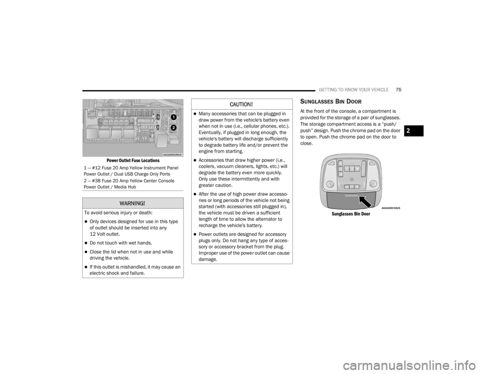
Power Outlet Fuse Locations
SUNGLASSES BIN DOOR
At the front of the console, a compartment is
provided for the storage of a pair of sunglasses.
The storage compartment access is a “push/
push” design. Push the chrome pad on the door
to open. Push the chrome pad on the door to
close.
Sunglasses Bin Door
1 — #12 Fuse 20 Amp Yellow Instrument Panel
Power Outlet / Dual USB Charge Only Ports
2 — #38 Fuse 20 Amp Yellow Center Console
Power Outlet / Media Hub
WARNING!
To avoid serious injury or death:
Only devices designed for use in this type
of outlet should be inserted into any
12 Volt outlet.
Do not touch with wet hands.
Close the lid when not in use and while
driving the vehicle.
If this outlet is mishandled, it may cause an
electric shock and failure.
CAUTION!
Many accessories that can be plugged in
draw power from the vehicle's battery even
when not in use (i.e., cellular phones, etc.).
Eventually, if plugged in long enough, the
vehicle's battery will discharge sufficiently
to degrade battery life and/or prevent the
engine from starting.
Accessories that draw higher power (i.e.,
coolers, vacuum cleaners, lights, etc.) will
degrade the battery even more quickly.
Only use these intermittently and with
greater caution.
After the use of high power draw accesso -
ries or long periods of the vehicle not being
started (with accessories still plugged in),
the vehicle must be driven a sufficient
length of time to allow the alternator to
recharge the vehicle's battery.
Power outlets are designed for accessory
plugs only. Do not hang any type of acces -
sory or accessory bracket from the plug.
Improper use of the power outlet can cause
damage.
2
20_LX_OM_EN_USC_t.book Page 75
Page 86 of 328

84GETTING TO KNOW YOUR INSTRUMENT PANEL
115 Volts AC Power Inverter System
Audio and Telematics System
Loss of the battery charge may indicate one or
more of the following conditions:
The charging system cannot deliver enough
electrical power to the vehicle system
because the electrical loads are larger than
the capability of the charging system. The
charging system is still functioning properly.
Turning on all possible vehicle electrical
loads (e.g. HVAC to max settings, exterior and
interior lights, overloaded power outlets
+12 Volts, 115 Volts AC, USB ports) during
certain driving conditions (city driving,
towing, frequent stopping).
Installing options like additional lights,
upfitter electrical accessories, audio
systems, alarms and similar devices.
Unusual driving cycles (short trips separated
by long parking periods).
The vehicle was parked for an extended
period of time (weeks, months).
The battery was recently replaced and was
not charged completely.
The battery was discharged by an electrical
load left on when the vehicle was parked.
The battery was used for an extended period
with the engine not running to supply radio,
lights, chargers, +12 Volt portable appli -
ances like vacuum cleaners, game consoles
and similar devices.
What to do when an electrical load reduction
action message is present (“Battery Saver On”
or “Battery Saver Mode”)
During a trip:
Reduce power to unnecessary loads if
possible:
Turn off redundant lights (interior or exte -
rior)
Check what may be plugged in to power
outlets +12 Volts, 115 Volts AC, USB
ports
Check HVAC settings (blower, tempera -
ture)
Check the audio settings (volume)
After a trip:
Check if any aftermarket equipment was
installed (additional lights, upfitter electrical accessories, audio systems, alarms) and
review specifications if any (load and Ignition
Off Draw currents).
Evaluate the latest driving cycles (distance,
driving time and parking time).
The vehicle should have service performed if
the message is still present during consecu
-
tive trips and the evaluation of the vehicle
and driving pattern did not help to identify the
cause.
WARNING LIGHTS AND MESSAGES
The warning/indicator lights will illuminate in
the instrument panel together with a dedicated
message and/or acoustic signal when
applicable. These indications are indicative and
precautionary and as such must not be
considered as exhaustive and/or alternative to
the information contained in the Owner’s
Manual, which you are advised to read carefully
in all cases. Always refer to the information in
this chapter in the event of a failure indication.
All active warning lights will display first if
applicable. The system check menu may
appear different based upon equipment
options and current vehicle status. Some
warning lights are optional and may not appear.
20_LX_OM_EN_USC_t.book Page 84
Page 304 of 328

302MULTIMEDIA
STEERING WHEEL AUDIO CONTROLS
The remote sound system controls are located
on the rear surface of the steering wheel at the
three and nine o’clock positions.
Steering Wheel Audio Controls
(Back View Of Steering Wheel)
The right-hand control is a rocker-type switch
with a push button in the center and controls
the volume and mode of the sound system.
Pushing the top of the rocker switch will
increase the volume, and pushing the bottom of
the rocker switch will decrease the volume.
Pushing the center button will make the radio
switch between the various modes available
(AM/FM/SXM/AUX, etc.). The left-hand control is a rocker-type switch with
a push button in the center. The function of the
left-hand control is different depending on
which mode you are in.
The following describes the left-hand control
operation in each mode.
RADIO OPERATION
Pushing the top of the switch will “Seek” up for
the next listenable station and pushing the
bottom of the switch will “Seek” down for the
next listenable station.
The button located in the center of the left-hand
control will tune to the next preset station that
you have programmed in the radio preset
button.
MEDIA MODE
Pushing the top of the switch once goes to the
next track on the selected media (USB/
Bluetooth®). Pushing the bottom of the switch
once goes to the beginning of the current track,
or to the beginning of the previous track if it is
within eight seconds after the current track
begins to play.
NOTE:
While In Media Mode, the center button on the
left rocker switch is nonfunctional.
AUX/USB CONTROL
This feature allows an external USB device to be
plugged into the USB port.
Plugging in a smartphone device to a USB Port
may activate Android Auto™ or Apple CarPlay®
features, if equipped. For further information,
refer to “Android Auto™” or “Apple CarPlay®” in
the Owner’s Manual Supplement.
AUX/USB Ports
1 — USB 1 Port
2 — AUX Jack
3 — USB 2 Port
20_LX_OM_EN_USC_t.book Page 302
Page 305 of 328

MULTIMEDIA303
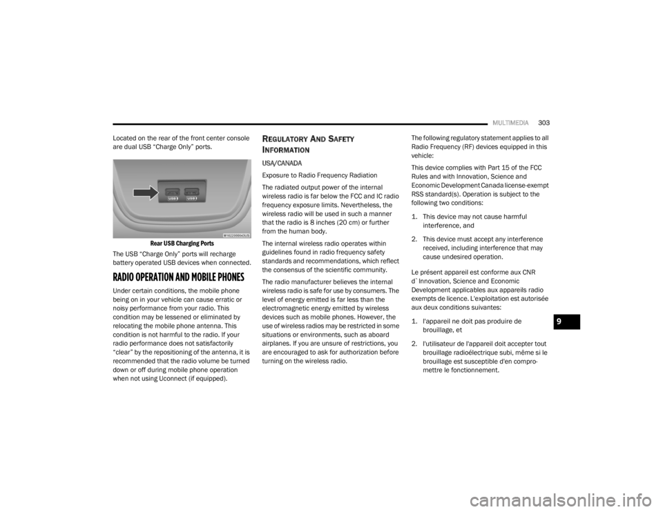
Located on the rear of the front center console
are dual USB “Charge Only” ports.
Rear USB Charging Ports
The USB “Charge Only” ports will recharge
battery operated USB devices when connected.
RADIO OPERATION AND MOBILE PHONES
Under certain conditions, the mobile phone
being on in your vehicle can cause erratic or
noisy performance from your radio. This
condition may be lessened or eliminated by
relocating the mobile phone antenna. This
condition is not harmful to the radio. If your
radio performance does not satisfactorily
“clear” by the repositioning of the antenna, it is
recommended that the radio volume be turned
down or off during mobile phone operation
when not using Uconnect (if equipped).
REGULATORY AND SAFETY
I
NFORMATION
USA/CANADA
Exposure to Radio Frequency Radiation
The radiated output power of the internal
wireless radio is far below the FCC and IC radio
frequency exposure limits. Nevertheless, the
wireless radio will be used in such a manner
that the radio is 8 inches (20 cm) or further
from the human body.
The internal wireless radio operates within
guidelines found in radio frequency safety
standards and recommendations, which reflect
the consensus of the scientific community.
The radio manufacturer believes the internal
wireless radio is safe for use by consumers. The
level of energy emitted is far less than the
electromagnetic energy emitted by wireless
devices such as mobile phones. However, the
use of wireless radios may be restricted in some
situations or environments, such as aboard
airplanes. If you are unsure of restrictions, you
are encouraged to ask for authorization before
turning on the wireless radio. The following regulatory statement applies to all
Radio Frequency (RF) devices equipped in this
vehicle:
This device complies with Part 15 of the FCC
Rules and with Innovation, Science and
Economic Development Canada license-exempt
RSS standard(s). Operation is subject to the
following two conditions:
1. This device may not cause harmful
interference, and
2. This device must accept any interference received, including interference that may
cause undesired operation.
Le présent appareil est conforme aux CNR
d`Innovation, Science and Economic
Development applicables aux appareils radio
exempts de licence. L'exploitation est autorisée
aux deux conditions suivantes:
1. l'appareil ne doit pas produire de brouillage, et
2. l'utilisateur de l'appareil doit accepter tout brouillage radioélectrique subi, même si le
brouillage est susceptible d'en compro -
mettre le fonctionnement.
9
20_LX_OM_EN_USC_t.book Page 303
Page 307 of 328

MULTIMEDIA305
You can interrupt the help message or
system prompts by pushing the VR or Phone
button and saying a Voice Command from
the current category.
Uconnect Voice Command Buttons
BASIC VOICE COMMANDS
The basic Voice Commands below can be given
at any point while using your Uconnect system.
Push the VR button . After the beep, say:
“Cancel ” to stop a current voice session
“Help ” to hear a list of suggested Voice
Commands
“ Repeat ” to listen to the system prompts
again
Uconnect 4C/4C NAV
Notice the visual cues that inform you of your
voice recognition system’s status. Cues appear
on the touchscreen.
RADIO
Use your voice to quickly get to the AM, FM, or
SiriusXM® Satellite Radio stations you would
like to hear. (Subscription or included
SiriusXM® Satellite Radio trial required).
Push the VR button . After the beep, say:
“ Tune to ninety-five-point-five FM”
“Tune to Satellite Channel Hits 1”
TIP:
At any time, if you are not sure of what to say or
want to learn a Voice Command, push the VR
button and say “ Help.” The system provides
you with a list of commands.
MEDIA
Uconnect offers connections via USB,
Bluetooth® and auxiliary ports (if equipped).
Voice operation is only available for connected
USB and AUX devices.
1 — Push To Initiate Or To Answer A Phone Call,
Send Or Receive A Text
2 — For All Radios: Push To Begin Radio, Media,
Or Climate Functions. For Uconnect 4C NAV Sys-
tem Only: Push To Begin Navigation Function
3 — Push To End Call
9
20_LX_OM_EN_USC_t.book Page 305
Page 310 of 328

308MULTIMEDIA
DO NOT DISTURB
With Do Not Disturb, you can disable
notifications from incoming calls and texts,
allowing you to keep your eyes on the road and
hands on the wheel. For your convenience,
there is a counter display to keep track of your
missed calls and text messages while you were
using Do Not Disturb.
Do Not Disturb can automatically reply with a
text message, a call, or both, when declining an
incoming call and send it to voicemail.
Automatic reply messages can be:
“I am driving right now, I will get back to you
shortly.”
Create a custom auto reply message up to
160 characters.
NOTE:
Only the first 25 characters can be seen on the
touchscreen while typing a custom message.
While in Do Not Disturb, Conference Call can be
selected so you can still place a second call
without being interrupted by incoming calls. NOTE:
Reply with text message is not compatible
with iPhones®.
Auto reply with text message is only available
on phones that support Bluetooth® MAP.
ANDROID AUTO™ — IF EQUIPPED
NOTE:
Feature availability depends on your carrier and
mobile phone manufacturer. Some Android
Auto™ features may or may not be available in
every region and/or language.
Android Auto™ allows you to use your voice to
interact with Android’s™ best-in-class speech
technology through your vehicle’s voice
recognition system, and use your smartphone’s
data plan to project your Android™-powered
smartphone and a number of its apps onto your
Uconnect touchscreen. Connect your Android™
5.0 or higher to one of the media USB ports,
using the factory-provided USB cable, and press
the new Android Auto™ icon that replaces your
“Phone” icon on the main menu bar to begin
Android Auto™. Push and hold the VR button on the steering wheel, or press and hold the
Microphone icon within Android Auto™, to
activate Android’s™ VR, which recognizes
natural voice commands, to use a list of your
smartphone’s features:
Maps
Music
Phone
Text Messages
Additional Apps
Refer to your Uconnect Owner’s Manual
Supplement for further information.
NOTE:
Requires compatible smartphone running
Android™ 5.0 or higher and download app on
Google Play. Android™, Android Auto™, and
Google Play are trademarks of Google Inc.
20_LX_OM_EN_USC_t.book Page 308