2020 CHRYSLER 300 length
[x] Cancel search: lengthPage 39 of 328

GETTING TO KNOW YOUR VEHICLE37
FRONT HEAD RESTRAINT REMOVAL
To remove the head restraint, raise it up as far
as it can go. Then, push the adjustment button
and the release button at the base of each post
while pulling the head restraint up. To reinstall
the head restraint, put the head restraint posts
into the holes. Then, adjust it to the appropriate
height.
NOTE:
Do not reposition the head restraint 180 degrees
to the incorrect position in an attempt to gain
additional clearance to the back of the head.
STEERING WHEEL
MANUAL TILT/TELESCOPING STEERING
C
OLUMN — IF EQUIPPED
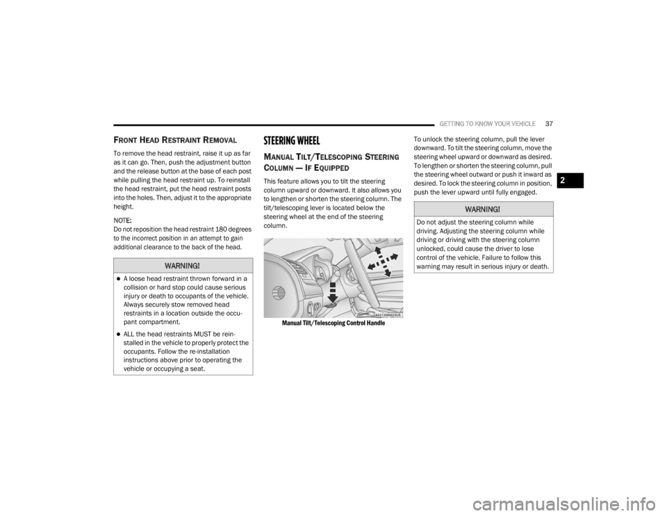
This feature allows you to tilt the steering
column upward or downward. It also allows you
to lengthen or shorten the steering column. The
tilt/telescoping lever is located below the
steering wheel at the end of the steering
column.
Manual Tilt/Telescoping Control Handle
To unlock the steering column, pull the lever
downward. To tilt the steering column, move the
steering wheel upward or downward as desired.
To lengthen or shorten the steering column, pull
the steering wheel outward or push it inward as
desired. To lock the steering column in position,
push the lever upward until fully engaged.
WARNING!
A loose head restraint thrown forward in a
collision or hard stop could cause serious
injury or death to occupants of the vehicle.
Always securely stow removed head
restraints in a location outside the occu
-
pant compartment.
ALL the head restraints MUST be rein -
stalled in the vehicle to properly protect the
occupants. Follow the re-installation
instructions above prior to operating the
vehicle or occupying a seat.
WARNING!
Do not adjust the steering column while
driving. Adjusting the steering column while
driving or driving with the steering column
unlocked, could cause the driver to lose
control of the vehicle. Failure to follow this
warning may result in serious injury or death.
2
20_LX_OM_EN_USC_t.book Page 37
Page 40 of 328

38GETTING TO KNOW YOUR VEHICLE
(Continued)
POWER TILT/TELESCOPING STEERING
C
OLUMN — IF EQUIPPED
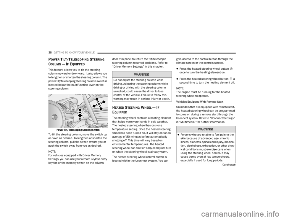
This feature allows you to tilt the steering
column upward or downward. It also allows you
to lengthen or shorten the steering column. The
power tilt/telescoping steering column switch is
located below the multifunction lever on the
steering column.
Power Tilt/Telescoping Steering Switch
To tilt the steering column, move the switch up
or down as desired. To lengthen or shorten the
steering column, pull the switch toward you or
push the switch away from you as desired.
NOTE:
For vehicles equipped with Driver Memory
Settings, you can use your remote keyless entry
key fob or the memory switch on the driver's door trim panel to return the tilt/telescopic
steering column to saved positions. Refer to
“Driver Memory Settings” in this chapter.
HEATED STEERING WHEEL — IF
E
QUIPPED
The steering wheel contains a heating element
that helps warm your hands in cold weather.
The heated steering wheel has only one
temperature setting. Once the heated steering
wheel has been turned on, it will stay on for an
average of 80 minutes before automatically
shutting off. This time will vary based on
environmental temperatures. The heated
steering wheel can shut off early or may not turn
on when the steering wheel is already warm.
The heated steering wheel control button is
located within the Uconnect system. You can gain access to the control button through the
climate screen or the controls screen.
Press the heated steering wheel button
once to turn the heating element on.
Press the heated steering wheel button a
second time to turn the heating element off.
NOTE:
The engine must be running for the heated
steering wheel to operate.
Vehicles Equipped With Remote Start
On models that are equipped with remote start,
the heated steering wheel can be programmed
to come on during a remote start through the
Uconnect system. Refer to “Uconnect Settings”
in “Multimedia” for further information.
WARNING!
Do not adjust the steering column while
driving. Adjusting the steering column while
driving or driving with the steering column
unlocked, could cause the driver to lose
control of the vehicle. Failure to follow this
warning may result in serious injury or death.
WARNING!
Persons who are unable to feel pain to the
skin because of advanced age, chronic
illness, diabetes, spinal cord injury, medica -
tion, alcohol use, exhaustion, or other phys -
ical conditions must exercise care when
using the steering wheel heater. It may
cause burns even at low temperatures,
especially if used for long periods.
20_LX_OM_EN_USC_t.book Page 38
Page 77 of 328

GETTING TO KNOW YOUR VEHICLE75
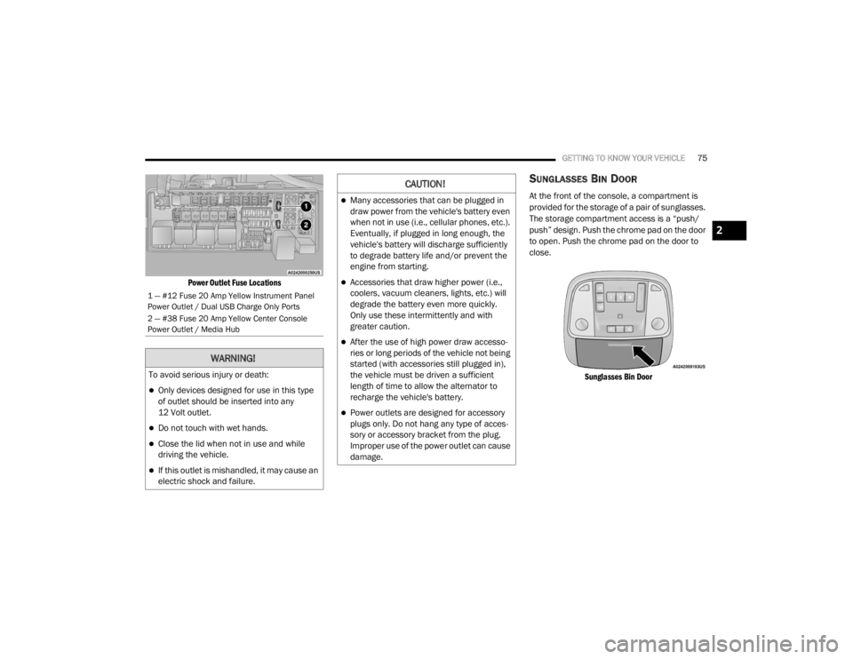
Power Outlet Fuse Locations
SUNGLASSES BIN DOOR
At the front of the console, a compartment is
provided for the storage of a pair of sunglasses.
The storage compartment access is a “push/
push” design. Push the chrome pad on the door
to open. Push the chrome pad on the door to
close.
Sunglasses Bin Door
1 — #12 Fuse 20 Amp Yellow Instrument Panel
Power Outlet / Dual USB Charge Only Ports
2 — #38 Fuse 20 Amp Yellow Center Console
Power Outlet / Media Hub
WARNING!
To avoid serious injury or death:
Only devices designed for use in this type
of outlet should be inserted into any
12 Volt outlet.
Do not touch with wet hands.
Close the lid when not in use and while
driving the vehicle.
If this outlet is mishandled, it may cause an
electric shock and failure.
CAUTION!
Many accessories that can be plugged in
draw power from the vehicle's battery even
when not in use (i.e., cellular phones, etc.).
Eventually, if plugged in long enough, the
vehicle's battery will discharge sufficiently
to degrade battery life and/or prevent the
engine from starting.
Accessories that draw higher power (i.e.,
coolers, vacuum cleaners, lights, etc.) will
degrade the battery even more quickly.
Only use these intermittently and with
greater caution.
After the use of high power draw accesso -
ries or long periods of the vehicle not being
started (with accessories still plugged in),
the vehicle must be driven a sufficient
length of time to allow the alternator to
recharge the vehicle's battery.
Power outlets are designed for accessory
plugs only. Do not hang any type of acces -
sory or accessory bracket from the plug.
Improper use of the power outlet can cause
damage.
2
20_LX_OM_EN_USC_t.book Page 75
Page 104 of 328

102SAFETY
Traction Control System (TCS)
The Traction Control System (TCS) monitors the
amount of wheel spin of each of the driven
wheels. If wheel spin is detected, the TCS may
apply brake pressure to the spinning wheel(s)
and/or reduce engine power to provide
enhanced acceleration and stability. A feature
of the TCS, Brake Limited Differential (BLD),
functions similar to a limited slip differential
and controls the wheel spin across a driven
axle. If one wheel on a driven axle is spinning
faster than the other, the system will apply the
brake of the spinning wheel. This will allow more
engine torque to be applied to the wheel that is
not spinning. BLD may remain enabled even if
TCS and ESC are in a reduced mode.AUXILIARY DRIVING SYSTEMS
BLIND SPOT MONITORING (BS M) — IF
E
QUIPPED
The Blind Spot Monitoring (BSM) system uses
two radar sensors, located inside the rear
bumper fascia, to detect highway licensable
vehicles (automobiles, trucks, motorcycles,
etc.) that enter the blind spot zones from the
rear/front/side of the vehicle.
Rear Detection Zones
When the vehicle is started, the BSM warning
light will momentarily illuminate in both outside
rearview mirrors to let the driver know that the
system is operational. The BSM system sensors
operate when the vehicle is in any forward gear
or REVERSE.
BSM Warning Light
The BSM detection zone covers approximately one
lane width on both sides of the vehicle 12 ft
(3.8 m). The zone length starts at the outside rear
view mirror and extends approximately 10 ft (3 m)
beyond the rear bumper of the vehicle. The BSM
system monitors the detection zones on both
sides of the vehicle when the vehicle speed
reaches approximately 6 mph (10 km/h) or higher
and will alert the driver of vehicles in these areas.
NOTE:
The BSM system DOES NOT alert the driver
about rapidly approaching vehicles that are
outside the detection zones.
20_LX_OM_EN_USC_t.book Page 102
Page 290 of 328

288MULTIMEDIA
Voice
After pressing the Voice button on the touchscreen, the following settings will be available:
Clock
After pressing the Clock button on the
touchscreen, the following settings will be
available:
Setting Name Selectable Options
Voice Response LengthBrief Detailed
Show Command List Neverw/Help Always
Setting Name Selectable Options
Sync Time With GPS — If Equipped OnOff
NOTE:
The “Sync Time With GPS” feature will allow you to automatically have the radio set the time. Set Time Hours +–
Set Time Minutes +–
Time Format 12 hrs
24 hrs
AM PM
Show Time In Status Bar — If Equipped OnOff
NOTE:
The “Show Time In Status Bar” feature will allow you to turn on or shut off the digital clock in the status bar.
20_LX_OM_EN_USC_t.book Page 288