2019 VOLVO XC60 TWIN ENGINE lock
[x] Cancel search: lockPage 581 of 695

WHEELS AND TIRES
}}
579
NOTE
The sealing compound effectively seals tireswith punctures in the tread but may not beable to fully seal tires with punctures in thesidewall. Do not use the tire sealing systemon tires with large tears, cracks or similardamage.
NOTE
The compressor is intended for temporary tiresealing and is approved by Volvo.
Location
The tire sealing system is located in a foam blockunder the floor of the cargo compartment.
Sealing compound expiration date
The sealing compound bottle must be replaced ifits expiration date has passed (see the decal onthe bottle). Handle the old bottle as hazardouswaste.
Related information
Using the tire sealing system (p. 579)
Inflate tires with the compressor included inthe tire sealing system (p. 583)
Tires (p. 556)
Using the tire sealing system
Sealing a tire using the tire sealing system, theTemporary Mobility Kit (TMK).
Overview
Electrical cable
Hose
Air release valve
Protective hose cover
Speed limit sticker
Bottle holder (orange cover)
Air pressure gauge
16Certain models only.17Not available on all models.
Page 594 of 695

LOADING, STORAGE AND PASSENGER COMPARTMENT
* Option/accessory.592
Using the electrical outlets
The 12 V outlet can be used for devicesintended for this such as MP3 players, coolersand cellular phones.
The high-voltage outlet* can be used for devicesintended for this, such as chargers, laptops, etc.
The ignition must be in at least mode I for theoutlets to supply current. The outlets will then beactive as long as there is sufficient charge in thestart battery.
If the engine is turned off and the vehicle islocked, the outlets will be deactivated. If theengine is turned off and the vehicle remainsunlocked, the sockets will remain active for up to7 minutes.
NOTE
Bear in mind that using the electrical outletswhen the engine is off could cause the starterbattery to have too low of a charge level,which could limit other functionality.
Accessories connected to the electrical out-lets can be activated even when the vehicleelectrical system is off or if preconditioning isused. For this reason, disconnect plugs whenthey are not in use to prevent the starter bat-tery from becoming discharged.
WARNING
Do not use accessories with large orheavy plugs – they could damage the out-let or come loose while you are driving.
Do not use accessories that could causedisruptions to e.g. the vehicle's radioreceiver or electrical system.
Position the accessory so that there is norisk of it injuring the driver or passengersin the event of heavy braking or a colli-sion.
Pay attention to connected accessoriesas they can generate heat that could burnpassengers or the interior.
Using 12 V outlets
1. Remove the stopper (tunnel console) or folddown the cover (trunk/cargo compartment)over the socket and plug in the device.
2. Unplug the device and put the stopper backin (tunnel console) or fold up the cover(trunk/cargo compartment) when the socketis not in use or left unattended.
CAUTION
The maximum power is 120 W (10 A) peroutlet.
Using high-voltage outlets
The ignition must be in at least mode I for outletsto supply current. The outlets will then be activeas long as there is sufficient charge in the startbattery.
1.Slide down the cover over the outlet and plugin the device.
>The LED2 light on the outlet will indicateits status.
2. The outlet is supplying electrical currentwhen the light is glowing steadily green.
3. Disconnect the device by pulling out the plug(do not pull on the cord).
Pull up the cover when the outlet is not inuse or is left unattended.
CAUTION
The maximum power is 150 W.
WARNING
Do not attempt to alter or repair the high-volt-age outlet on your own. Volvo recommendscontacting an authorized Volvo workshop.
2LED (Light Emitting Diode)
Page 595 of 695

LOADING, STORAGE AND PASSENGER COMPARTMENT
}}
* Option/accessory.593
WARNING
Only use accessories that are not dam-aged or malfunctioning. The accessoriesmust be designed for 120 V and 60 Hz,with plugs intended for the outlet. Theaccessories must be CE marked, ULmarked or have an equivalent safetymarking.
New let outlets, plugs or accessoriescome into contact with water or anotherfluid. Do not touch or use the outlet if itappears damaged or has been in contactwith water or another fluid.
Do not connect power strips, adapters orextension cords to the outlet has thiscould cause the outlet's safety functionsto malfunction.
The outlet is equipped with a pet guard.Make sure that no one picks at or dam-ages the outlet in such a way that theguard is disabled. Children should not beleft unsupervised in the vehicle when theoutlet is active.
Failure to follow the above could lead tosevere or fatal electrical shocks.
Related information
Electrical outlets (p. 590)
Passenger compartment interior (p. 588)
Using the glove compartment
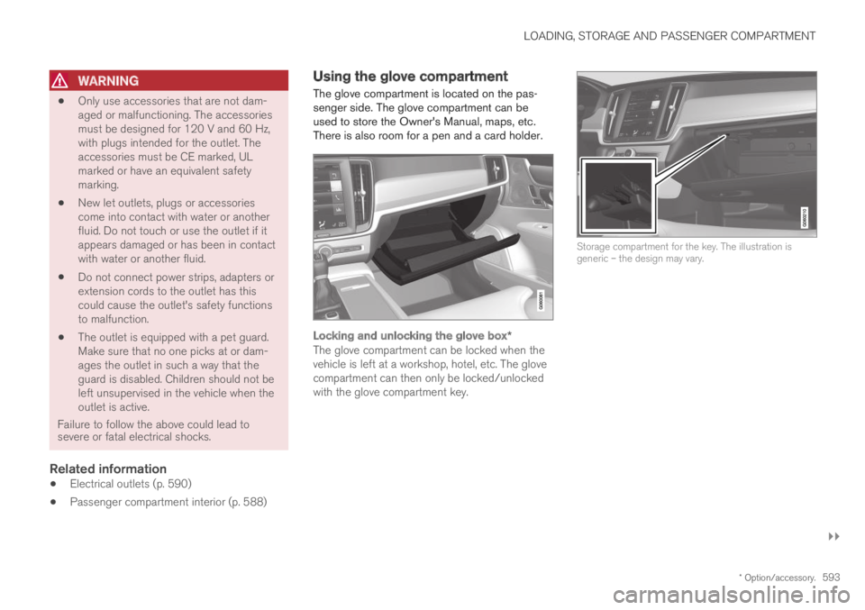
The glove compartment is located on the pas-senger side. The glove compartment can beused to store the Owner's Manual, maps, etc.There is also room for a pen and a card holder.
Locking and unlocking the glove box *
The glove compartment can be locked when thevehicle is left at a workshop, hotel, etc. The glovecompartment can then only be locked/unlockedwith the glove compartment key.
Storage compartment for the key. The illustration isgeneric – the design may vary.
Page 596 of 695

||
LOADING, STORAGE AND PASSENGER COMPARTMENT
* Option/accessory.594
The illustration is generic – the design may vary.
To lock the glove compartment:
Insert the key into the lock on the glove com-partment.
Turn the key 90 degrees clockwise.
Remove the key from the lock.
–To unlock, perform the above steps inreverse.
Using the glove box as a cooled area *
The glove compartment can be used to cool e.g.drinks or food. Cooling is possible when the cli-mate system is active (i.e. when the ignition is inmode II or when the engine is running).
The illustration is generic – the design may vary.
Activate cooling
Deactivate cooling
–Activate or deactivate cooling by moving thecontrol as far as possible toward the passen-ger compartment/glove compartment.
Related information
Passenger compartment interior (p. 588)
Private Locking (p. 265)
Sun visors
In the ceiling in front of the driver and front pas-senger, there are sun visors that can be loweredand angled to the side as necessary.
The illustration is generic – the design may vary.
The mirror lighting* comes on automatically whenthe cover is lifted up.
The mirror frame has a holder for e.g. cards ortickets.
Related information
Passenger compartment interior (p. 588)
Page 600 of 695

LOADING, STORAGE AND PASSENGER COMPARTMENT
* Option/accessory.598
Load anchoring eyelets
The load anchoring eyelets in the cargo com-partment can be used to secure objects withstraps, a net, etc.
WARNING
Hard, sharp and/or heavy objects in or pro-truding from the vehicle can cause injury inthe event of hard braking.
Always secure large and heavy objects with aseat belt or cargo retaining straps.
Related information
Loading recommendations (p. 595)
Weights (p. 667)
Rear seat ski hatch
The hatch in the rear seat backrest can beopened to transport long, narrow objects suchas skis.
The illustration is generic - details may vary according tovehicle model.
1. In the cargo compartment, grasp the skihatch handle and pull it down.
2.Fold down the armrest in the rear seat.
If the private locking function is used, the skihatch must be closed.
Related information
Loading recommendations (p. 595)
Private Locking (p. 265)
Load anchoring eyelets (p. 598)
Installing and removing the cargo
compartment cover*
In the fully open position, the cover and the rearflap conceal objects in the cargo compartment.
Installing the cargo compartment cover
Press the end piece on one side of the coverinto the retaining bracket in the side panel ofthe cargo compartment.
Page 606 of 695

||
LOADING, STORAGE AND PASSENGER COMPARTMENT
604
WARNING
Objects in the cargo compartment mustalways be securely anchored, even with a cor-rectly installed cargo net.
Installing the cargo net
WARNING
All of the cargo net's upper consoles, hooksand straps must be securely mounted andattached before the net is used.
Never use the net if it is damaged.
NOTE
With front mounting, the cargo net is mosteasily installed via a rear door.
1. Fold out the cargo net and make sure thatthe upper rod folds out and locks into posi-tion.
2.Insert one of the net's hooks into the front orrear ceiling mounting point with the straplock facing you.
3. Insert the net's other upper hook into theceiling mounting point on the opposite side.
The telescopic spring-loaded hooks makemounting easier.
Make sure that the net's hooks are pushedforward as far as possible into their respec-tive mounting points.
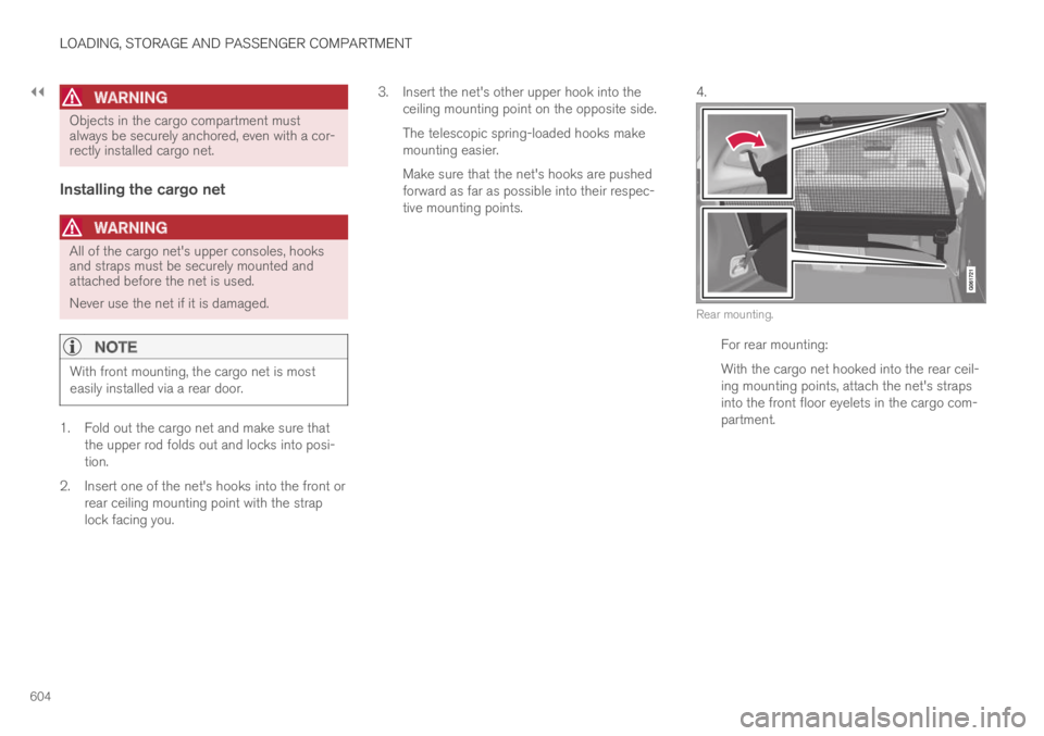
4.
Rear mounting.
For rear mounting:
With the cargo net hooked into the rear ceil-ing mounting points, attach the net's strapsinto the front floor eyelets in the cargo com-partment.
Page 607 of 695

LOADING, STORAGE AND PASSENGER COMPARTMENT
605
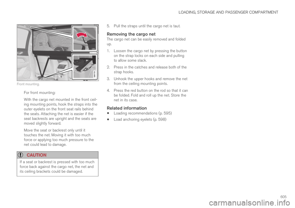
Front mounting.
For front mounting:
With the cargo net mounted in the front ceil-ing mounting points, hook the straps into theouter eyelets on the front seat rails behindthe seats. Attaching the net is easier if theseat backrests are upright and the seats aremoved slightly forward.
Move the seat or backrest only until ittouches the net. Moving it with too muchforce or applying too much pressure to thenet could lead to damage.
CAUTION
If a seat or backrest is pressed with too muchforce back against the cargo net, the net andits ceiling brackets could be damaged.
5. Pull the straps until the cargo net is taut.
Removing the cargo net
The cargo net can be easily removed and foldedup.
1. Loosen the cargo net by pressing the buttonon the strap locks on each side and pullingto allow some slack.
2. Press in the catches and release both of thestrap hooks.
3. Unhook the upper hooks and remove the netfrom the ceiling mounting points.
4. Press the red button on the rod so that it canbe folded. Fold and roll up the net. Store thenet in its case.
Related information
Loading recommendations (p. 595)
Load anchoring eyelets (p. 598)
Page 612 of 695

||
MAINTENANCE AND SERVICE
610
Monthly:
Check cold tire pressure in all tires. Inspectthe tires for wear.
Check that engine coolant and other fluidlevels are between the indicated "min" and"max" markings.
Clean interior glass surfaces with a glasscleaner and soft paper towels.
Wipe driver information displays with a softcloth.
Visually inspect battery terminals for corro-sion. Corrosion may indicate a loose terminalconnector, or a battery near the end of itsuseful service life. Consult your Volvo retailerfor additional information.
As needed:
Wash the car, including the undercarriage, toreduce wear that can be caused by a buildup ofdirt, and corrosion that can be caused by salt res-idues.
Clean leaves and twigs from air intake vents atthe base of the windshield, and from other placeswhere they may collect.
NOTE
Complete service information for qualifiedtechnicians is available online for purchase orsubscription at www.volvotechinfo.com.
Related information
Vehicle status (p. 612)
Scheduling service and repairs (p. 613)
Connecting equipment to the vehicle's datalink connector (p. 37)
Technician certification (p. 38)
Climate control system service (p. 619)
Maintenance of the brake system (p. 438)
Engine compartment overview (p. 620)
Data transfer between vehicle andworkshop over Wi-Fi
Volvo workshops have a designated Wi-Fi net-work for secure data transfer between your vehi-cle and the workshop. Your visit to the workshopwill be easier and more effective when diagnos-tics information and software can be transferredover the workshop's network.
When you arrive at the workshop, your servicetechnician can connect your vehicle to the work-shop's Wi-Fi network to perform troubleshootingand download software. For this type of commu-nication, the vehicle only connects to a work-shop's network. It is not possible to connect thevehicle to another Wi-Fi network (e.g. your homenetwork) in the same way as to a workshop's net-work.
Connecting with remote key
Connection is usually managed by the servicetechnician, who will use the remote key buttons. Itis therefore important to bring a key with buttonswith you when you visit the workshop. Pressingthe lock button on the remote key three times willconnect the vehicle to the workshop's Wi-Fi net-work.
When the car is connected to a Wi-Fi network,
the symbol appears in the center display.