2019 VOLKSWAGEN TRANSPORTER stop
[x] Cancel search: stopPage 168 of 486
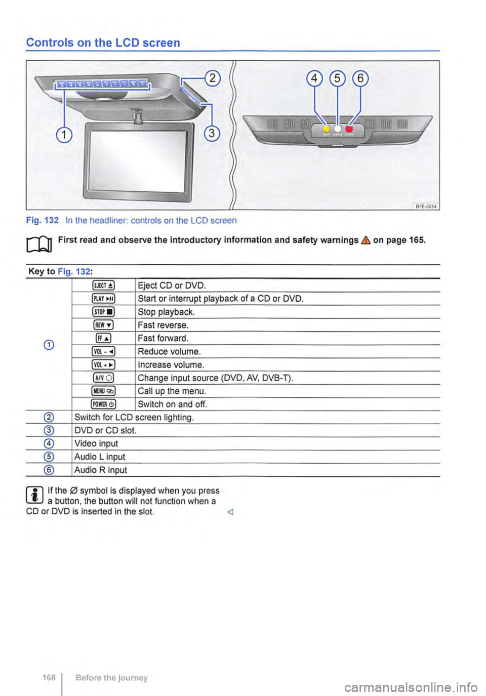
Controls on the LCD screen
Fig. 132 In the headliner: controls on the LCD screen
m First read and observe the Introductory Information and safety warnings & on page 165.
Key to Fig 132·
Eject CD or DVD.
illAY •uJ Start or interrupt playback of a CD or DVD.
lsTor•l Stop playback.
IREW ,.] Fast reverse.
G) ([;) Fast forward.
lvOl--.) Reduce volume.
lvOl • •I Increase volume.
IA/YO) Change input source (DVD, AV, DVB-T).
lllli.JQ,) Call up the menu.
IPOm) Switch on and off.
® Switch for LCD screen lighting.
@ DVD or CD slot.
® Video input
® Audio L input
® Audio R input
rll If the 0 symbol is displayed when you press L!.J a button. the button will not function when a CD or DVD is inserted in the slot.
Page 170 of 486
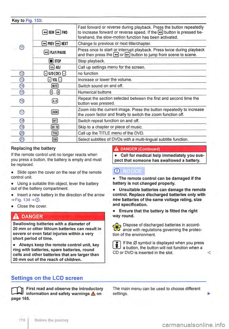
Key to Fig 133·
8REW8FWD Fast forward or reverse during playback. Press the button repeatedly to increase forward or reverse speed. If the§) button is pressed be-forehand, the slow-motion function has been activated.
@ §)PREY 81£XT Change to previous or next title/chapter.
§) PLAY /PAUSE Press once to start or interrupt playback. Press twice during playback and then press the B or 8 button to jump from scene to scene.
@STOP Stop playback.
Call up settings menu for the screen.
© (!) U/D(CH) Q no function
@ (!)VO!.Q Increase or lower the volume.
®l Switch sound on and off.
@ (ij ... (i) Numerical buttons
® @ Repeat the section selected between the first and second time the button was pressed.
@ Zoom into the current image. Press the button repeatedly to increase the zoom factor and finally to switch the zoom function off.
@ @) Switch repeat function on and off.
@ Skip to a chapter or piece of music.
@ §D Call up the TITLE menu of the DVD.
@ @ Select subtitles of DVDs with a multi-lingual subtitle function.
Replacing the battery
If the remote control unit no longer reacts when you press a button. the battery is empty and must be replaced.
• Slide open the cover on the rear of the remote control unit.
• Using a suitable thin object, lever the battery out of the battery compartment.
• Insert a new battery in the direction of the arrow 134
• Close the cover.
Swallowing batteries with a diameter of 20 mm or other lithium batteries can result in severe or even fatal injuries within a very short period of time.
• Always keep the remote control unit, key ring with batteries, spare batteries, round cells and other batteries that are larger than 20 mm out of the reach of children.
Settings on the LCD screen
rl'11 First read and observe the introductory L-W.f information and safety warnings & on page 165.
170 I Before the journey
• Call for medical help immediately you sus-pect that someone has swallowed a battery.
CD
• The remote control can be damaged if the battery is not changed properly.
• Unsuitable batteries can damage the remote control. Replace discharged batteries only with new batteries of the same voltage rating, size and specification.
• Ensure that the battery Is fitted the right way round.
Dispose of discharged batteries in accord-W ance with regulations governing the protec-tion of the environment.
r::l If the 0 symbol is displayed when you press l!J a button, the button will not function when a CD or DVD is inserted in the slot.
Page 195 of 486
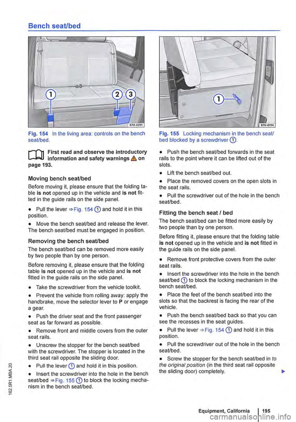
Bench seat/bed
Fig. 154 In the living area: controls on the bench seat/bed.
ill1 First read and observe the introductory l-J::,jJ information and safety warnings & on page 193.
Moving bench seat/bed
Before moving it, please ensure that the folding ta-ble is not opened up in the vehicle and is not fit-ted in the guide rails on the side panel.
• Pull the lever '*Fig. 154 CD and hold it in this position.
• Move the bench seat/bed and release the lever. The bench seat/bed must be engaged in position.
Removing the bench seat/bed
The bench seat/bed can be removed more easily by two people than by one person.
Before removing it, please ensure that the folding table is not opened up in the vehicle and is not fitted in the guide rails on the side panel.
• Take the screwdriver from the vehicle tool kit.
• Prevent the vehicle from rolling away: apply the handbrake, move the selector lever to P or engage a gear.
• Push the driver seat and the front passenger seat as far forward as possible.
• Remove front and middle covers from the outer seat rails.
• Unscrew the stopper for the bench seat/bed with the screwdriver. The stopper is located in the third seat rail opposite the sliding door.
• Pull the lever G) and hold it in this position.
• Insert the screwdriver into the hole in the bench seat/bed =>Fig. 155 G) to block the locking mecha-nism in the bench seat/bed.
Fig. 155 Locking mechanism in lhe bench seat/ bed blocked by a screwdriver G).
• Push the bench seat/bed forwards in the seat rails to the point where it can be lifted out of the slots.
• Lift the bench seat/bed out.
• Place the removed covers on the open slots in the seat rails.
• Pull the screwdriver out of the hole in the bench seat/bed.
Fitting the bench seat I bed
The bench seat/bed can be fitted more easily by two people than by one person.
Before fitting it, please ensure that the folding table is not opened up in the vehicle and is not fitted in the guide rails on the side panel.
• Remove front protective covers from the outer seat rails.
• Insert the screwdriver into the hole in the bench seat/bed G) to block the locking mechanism in the bench seat/bed.
• Place the feet of the bench seat/bed into the slots so that the backrest is facing the rear of the vehicle.
• Push the bench seat/bed back so that you can see the recesses in the seat guides.
• Pull the lever =>Fig. 154 G) and hold it in this position.
• Pull the screwdriver out of the hole in the bench seat/bed.
• Screw the stopper for the bench seat/bed in to the original position (in the third seat rail opposite the sliding door) completely. .,.
Equipment, California 195
Page 196 of 486
• Make sure that the backrest of the bench seaU bed is in the upright position and securely engag-ed.
Bed (bench seat/bed)
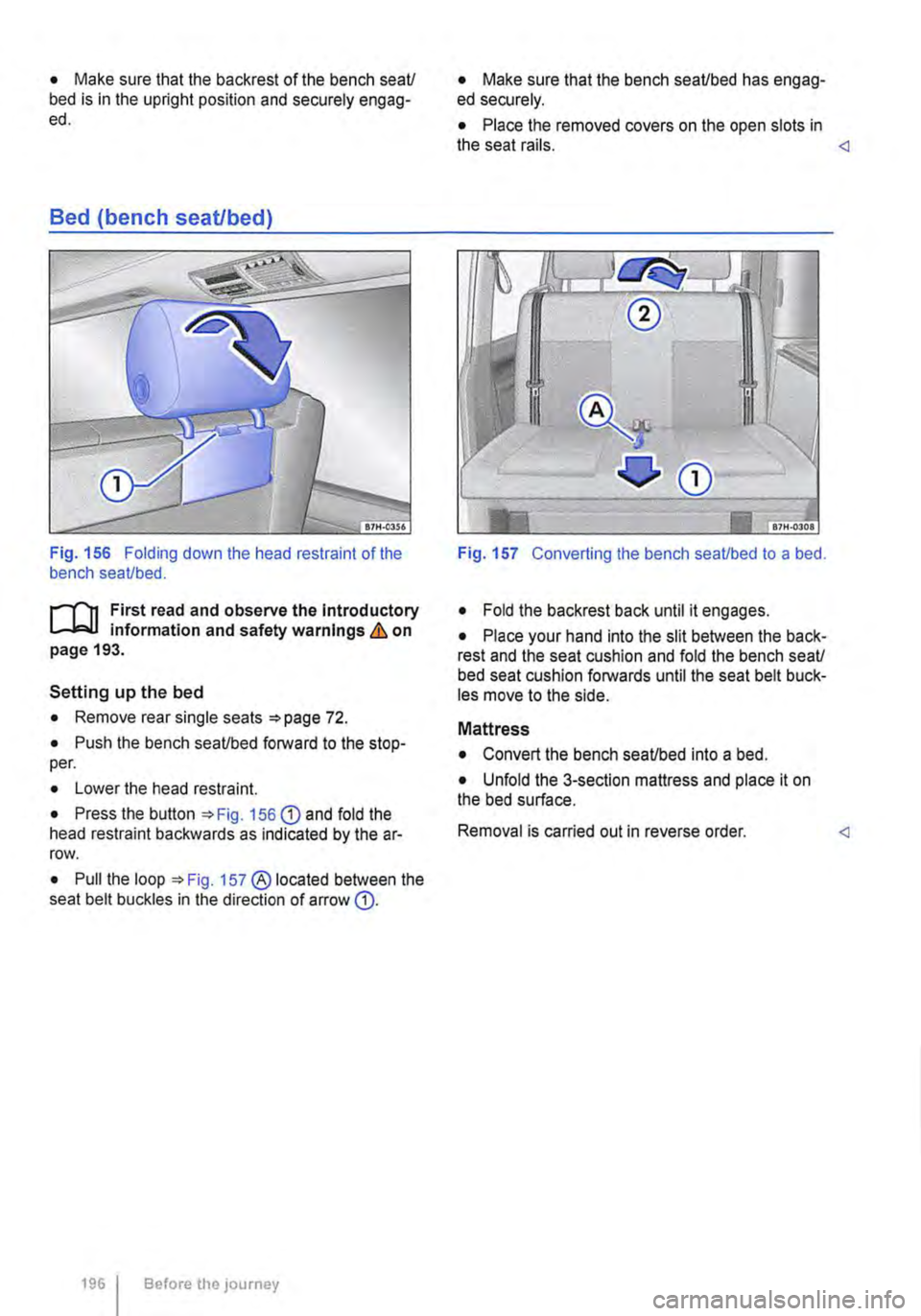
Fig. 156 Folding down the head restraint of the bench seaUbed.
r-111 First read and observe the Introductory 1-J,::JJ information and safety warnings & on page 193.
Setting up the bed
• Remove rear single seats =>page 72.
• Push the bench seaUbed forward to the stop-per.
• Lower the head restraint.
• Press the button =>Fig. 156 G) and fold the head restraint backwards as indicated by the ar-row.
• Pull the loop =>Fig. 157 ® located between the seat belt buckles in the direction of arrow G).
1961 Before the journey
• Make sure that the bench seaUbed has engag-ed securely.
• Place the removed covers on the open slots in the seat rails.
• Fold the backrest back until it engages.
• Place your hand into the slit between the back-rest and the seat cushion and fold the bench seaU bed seat cushion forwards until the seat belt buck-les move to the side.
Mattress
• Convert the bench seaUbed into a bed.
• Unfold the 3-section mattress and place it on the bed surface.
Removal is carried out in reverse order.
Page 198 of 486
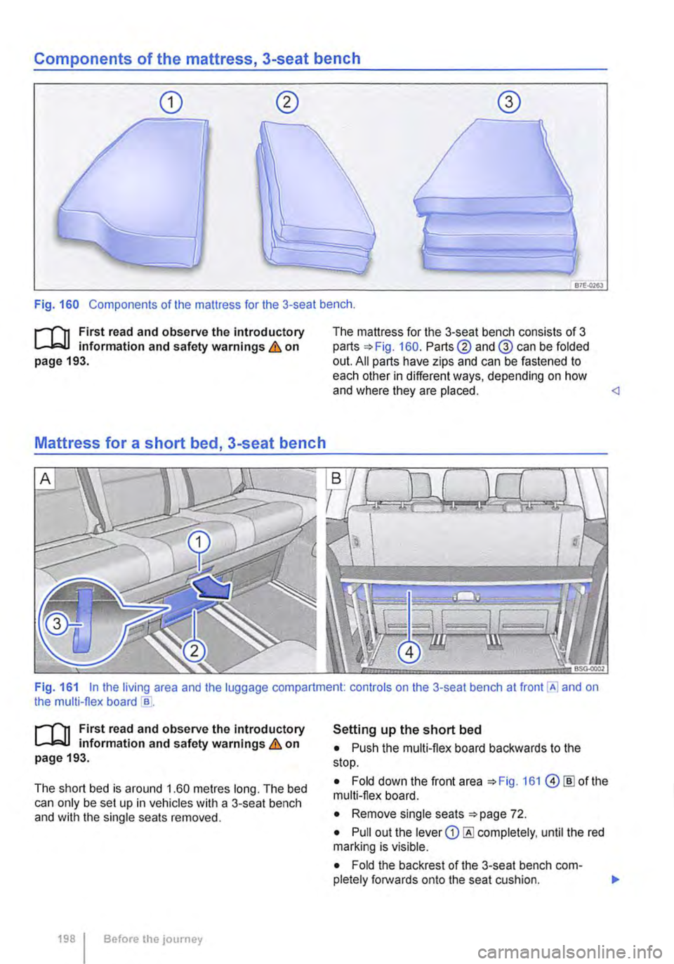
Components of the mattress, 3-seat bench
87E-0263
Fig. 160 Components of the mattress for the 3-seat bench .
.--m First read and observe the introductory l.-l=.U information and safety warnings & on page 193.
Mattress for a short bed, 3-seat bench
The mattress for the 3-seat bench consists of 3 parts 160. Parts@ and@ can be folded out. All parts have zips and can be fastened to each other in different ways, depending on how and where they are placed.
.--m First read and observe the Introductory l.-l=.U information and safety warnings & on page 193.
The short bed is around 1.60 metres long. The bed can only be set up in vehicles with a 3-seat bench and with the single seats removed.
198 I Before the journey
Setting up the short bed
• Push the multi-flex board backwards to the stop.
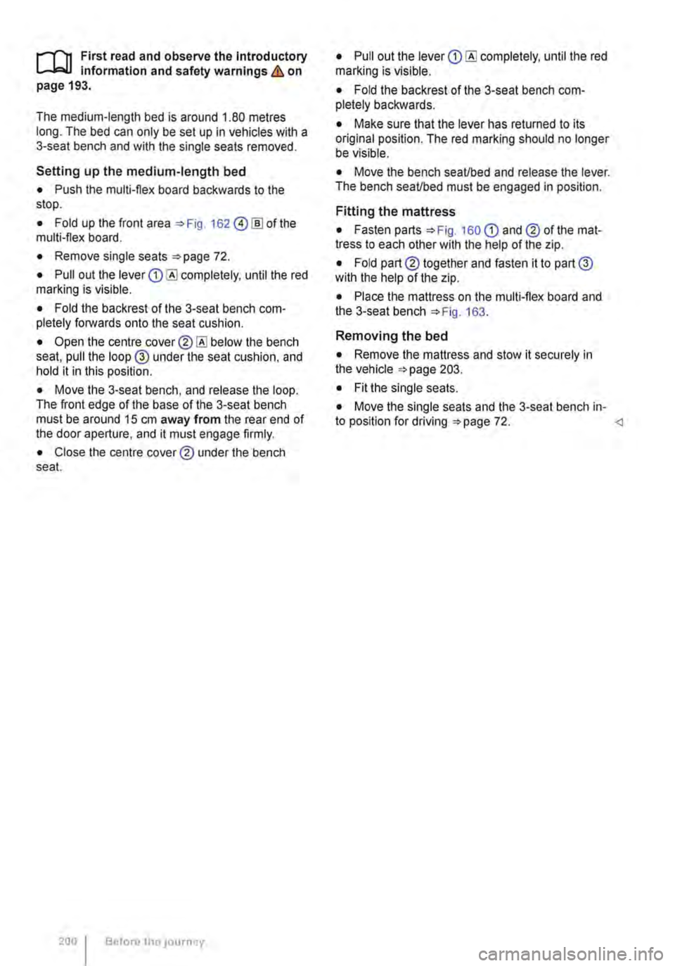
• Fold down the front area 161 @[ID of the multi-flex board.
• Remove single seats 72.
• Pull out the lever CD completely, until the red marking is visible.
• Fold the backrest of the 3-seat bench com-pletely forwards onto the seat cushion. 11>
Page 200 of 486
,...-m First read and observe the Introductory L--W.I Information and safety warnings & on page 193.
The medium-length bed is around 1.80 metres long. The bed can only be set up In vehicles with a 3-seat bench and with the single seats removed.
Setting up the medium-length bed
• Push the multi-flex board backwards to the stop.
• Fold up the front area 162 @!ID of the multi-flex board.
• Remove single seats 72.
• Pull out the lever completely, until the red marking is visible.
• Fold the backrest of the 3-seat bench com-pletely forwards onto the seat cushion.
• Open the centre below the bench seat, pull the loop @ under the seat cushion, and hold it in this position.
• Move the 3-seat bench, and release the loop. The front edge of the base of the 3-seat bench must be around 15 cm away from the rear end of the door aperture, and it must engage firmly.
• Close the centre cover® under the bench seat.
200 Before tho JOurney
• Pull out the lever completely, until the red marking is visible.
• Fold the backrest of the 3-seat bench com-pletely backwards.
• Make sure that the lever has returned to its original position. The red marking should no longer be visible.
• Move the bench seaUbed and release the lever. The bench seaUbed must be engaged in position.
Fitting the mattress
• Fasten parts 160 CD and® of the mat-tress to each other with the help of the zip.
• Fold part® together and fasten it to part@ with the help of the zip.
• Place the mattress on the multi-flex board and the 3-seat bench 163.
Removing the bed
• Remove the mattress and stow it securely in the vehicle 203.
• Fit the single seats.
• Move the single seats and the 3-seat bench in-to position for driving 72.
Page 201 of 486
Mattress for a long bed, 3-seat bench
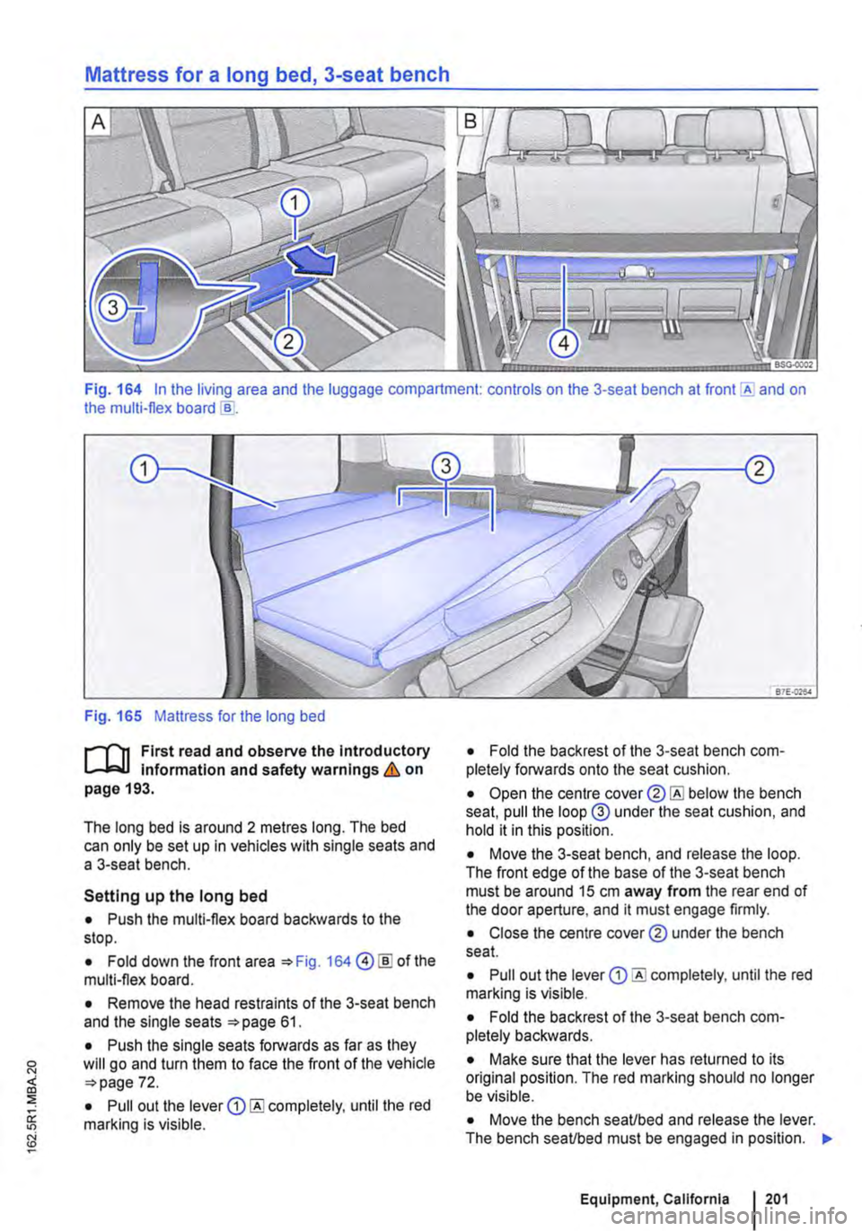
Fig. 164 In the living area and the luggage compartment: controls on the 3-seat bench at and on the multi-flex board
Fig. 165 Mattress for the long bed
r-1'lt First read and observe the Introductory L-J,:::..U Information and safety warnings & on page 193.
The long bed is around 2 metres long. The bed can only be set up in vehicles with single seats and a 3-seat bench.
Setting up the long bed
• Push the multi-flex board backwards to the stop.
• Fold down the front area 164@ [ID of the multi-flex board.
• Remove the head restraints of the 3-seat bench and the single seats 61.
• Push the single seats forwards as far as they will go and turn them to face the front of the vehicle 72.
• Pull out the lever completely, until the red marking is visible.
• Fold the backrest of the 3-seat bench com-pletely forwards onto the seat cushion.
• Open the centre below the bench seat, pull the loop@ under the seat cushion, and hold it in this position.
• Move the 3-seat bench, and release the loop. The front edge of the base of the 3-seat bench must be around 15 cm away from the rear end of the door aperture, and it must engage firmly.
• Close the centre cover® under the bench seat.
• Pull out the lever completely, until the red marking is visible.
• Fold the backrest of the 3-seat bench com-pletely backwards.
• Make sure that the lever has returned to its original position. The red marking should no longer be visible.
• Move the bench seaUbed and release the lever. The bench seaUbed must be engaged in position. "'
Equipment, California 201
Page 206 of 486

Symbol Meaning
A Flow of electric current in amps
Lit up: 230-volt mains connection has been made and the battery charger is working. Flashing or displaying a number over 15 volts: malfunction. Disconnect the 230-volt mains connection and have the electrical system checked by a qualified workshop. Not lit up despite a 230-volt connection being made: there is a power cut or malfunction in the battery charger.
G The batteries are being charged by the alternator.
Warning messages
Under certain conditions, such as when the pop-up roof is open, warning messages appear on the dis-play when the engine is started. These warn against possible vehicle or equipment damage.
• Switch off the ignition and correct the cause of the warning message.
Malfunction
If a symbol flashes, there is a fault in the indicated system.
• Press the button G?) for five seconds to clear the fault. If this does not work or if other faults ap-pear, please contact a qualified workshop. Volks-wagen Commercial Vehicles recommends using a Volkswagen Commercial Vehicles dealership for this purpose.
A WARNING
Failure to observe illuminated warning lamps and text messages can lead to your vehicle breaking down in traffic, and can cause acci-dent and serious injury.
A WARNING (Continued)
• Never Ignore any Illuminated warning lamps or text messages.
• Stop the vehicle as soon as possible and when safe to do so.
• Stop the vehicle at a safe distance away from moving traffic and ensure that no part of the exhaust system can come Into contact with any Inflammable material underneath the vehicle, e.g. dry grass or fuel.
• Any broken-down vehicle poses an In-creased accident risk both for you and for other road users. If the situation requires, switch on the hazard warning lights and set up the warning triangle as a warning to other road users.
• Before opening the bonnet, switch off the engine and allow it to cool down sufficiently.
• The engine compartment of any motor ve-hicle is a dangerous area. Serious injuries can be sustained here 350.
CD
Failure to observe illuminated indicator lamps and text messages can lead to your vehicle be-ing damaged.
J'"'""'('n First read and observe the introductory L-J,:.IJ information given on page 204.
Main menu Possible functions
Pop-up roof Opening
Closing
Displays Outside temperature
206 Before the journey
Using the menus
• Turn the rotary/push knob 168@ to highlight a function or submenu or to change a set-ting.
• Press the rotary/push knob to select a function or submenu or to confirm a setting.
Description of the submenu with examples
Open the pop-up roof .,1
Close the pop-up roof .,t
Current outside temperature (28.SO C) ...