2019 VOLKSWAGEN TRANSPORTER stop
[x] Cancel search: stopPage 57 of 486
• Close all windows and doors.
• Pull up the button for the window and hold it in this position for at least one second.
• Let go of the button then pull it up again and hold it in this position. One-touch opening and closing is now ready for operation.
The one-touch function can be restored for individ-ual windows or for several windows at the same time.
Convenience opening and closing
There are three different ways of opening and clos-ing all electric windows simultaneously when the ignition is switched off:
• Press and hold the locking or unlocking button in the remote control key.
• To interrupt this function, let go of the locking or unlocking button.
• OR: hold the vehicle key in the driver door lock cylinder in either the locking or the unlocking posi-tion until all windows are either opened or closed.
• To interrupt this function, turn the vehicle key in the opposite direction.
• OR: after switching the ignition off and opening the driver and front passenger doors, push or pull the@ button in the required direction for at least two seconds.
During convenience closing, first the windows and then the sliding/tilting roof will be closed.
A WARNING
Careless or unsupervised use of the electric windows can cause serious Injuries.
• The electric windows should only be opened or closed when you are sure that no-body is in their operating area.
• Never leave children or people requiring assistance alone In the vehicle when the ve-hicle is locked. The windows can no longer be opened In an emergency.
• Always take all vehicle keys with you ev-ery time you leave the vehicle. The windows can still be operated using the buttons sever-al minutes after the Ignition has been switch-ed off, provided that the driver door and front passenger door are not opened.
m One-touch opening and closing and the roii-L!J back function will not work if there is a fault in the electric windows. Go to a qualified workshop.
l"""l'l1 First read and observe the Introductory l-J,a,IJ Information and safety warnings & on page 55.
The roll-back function for the electric windows can reduce the risk of Injuries when the windows are closing :) &. If the one-touch closing function for a window does not work because it is stiff or is being obstructed, the window will automatically open again.
• Check to see why the window has not closed.
• Try to close the window again.
• If the window is again prevented from closing within approximately 10 seconds of the first at-tempt because it is stiff or obstructed, the automat-ic closing function is switched off for approximately 10 seconds.
• If the window is still obstructed, the window stops at this point. To close the window without the roll-back function, press the button again within 1 0 seconds :) &.
Closing the window without the roll-back function
• Try to close the window again within approxi-mately 10 seconds by holding the button. The roll-back function will be deactivated for a small section of the path of the closing window.
• If the closing procedure takes longer than ap-proximately 10 seconds, the roll-back function will be reactivated. The window will then stop again if it is stiff or meets another obstacle.
• Please go to a qualified workshop if the window still cannot be closed.
A WARNING
Closing the electric windows without the roll-back function could lead to severe Injuries.
• Always take care when closing electric windows. 11>
Opening and closing
Page 60 of 486
m The sliding/tilting roof rotary switch remains W in the last position selected If the roof is closed from outside the vehicle using convenience closing. lt will have to be re-positioned the next time you drive. <1
Roll-back function for the sliding/tilting roof
r-111 First read and observe the introductory l..-J.::-1.1 Information and safety warnings & on page 58.
The roll-back function can reduce the risk of injury when closing the sliding/tilting roof => &. If the slid-ing/tilting roof is unable to close because it is stuck or obstructed, it will open again automatically.
• Check to see why the sliding/tilting roof has not closed.
• Try to close the sliding/tilting roof again.
• If the sliding/tilting roof is still obstructed, the sliding/tilting roof stops at this point. The sliding/tilt-ing roof then closes without the roll-back function.
Closing without the roll-back function
• Push the rotary knob at the front in position =>Fig. 38 ®until the sliding/tilting roof Is fully closed.
• The sliding/tilting roof then closes without the roll-back function.
• Please go to a qualified workshop if the sliding/ tilting roof still cannot be closed.
Before the journey
A WARNING
Closing the sliding/tilting roof without the roll-back function can lead to severe injuries.
• Always close the sliding/tilting roof care-fully.
• Ensure that nobody obstructs the operat-Ing area of the sliding/tilting roof, especially if the roll-back function Is not active.
• The roll-back function does not prevent fingers or other body parts from being press-ed against the roof frame and sustaining in-jury.
m The roll-back function is also activated if the W windows and sliding/tilting roof are closed us-ing the driver door lock for convenience clos-Ing =>page 57. <1
Page 67 of 486
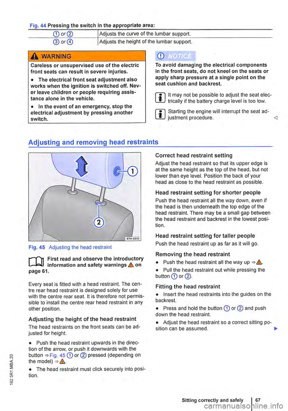
Fig. 44 Pressing the switch In the appropriate area:
CD or@ Adjusts the curve of the lumbar support.
@ or@ Adjusts the height of the lumbar support.
A wARNING
Careless or unsupervised use of the electric front seats can result in severe Injuries.
• The electrical front seat adjustment also works when the ignition is switched off. Nev-er leave children or people requiring assis-tance alone in the vehicle.
• In the event of an emergency, stop the electrical adjustment by pressing another switch.
CD
To avoid damaging the electrical components in the front seats, do not kneel on the seats or apply sharp pressure at a single point on the seat cushion and backrest.
m 11 may not be possible to adjust the seat elec-l!J trically if the battery charge level is too low.
m Starting the engine will interrupt the seat ad-l!J justment procedure.
Fig. 45 Adjusting the head restraint
r--("'n First read and observe the introductory L--J,::.U information and safety warnings & on page 61.
Every seat is fitted with a head restraint. The cen-tre rear head restraint is designed solely for use with the centre rear seat. 11 is therefore not permis-sible to install the centre rear head restraint in any other position.
Adjusting the height of the head restraint
The head restraints on the front seats can be ad-justed for height.
• Push the head restraint upwards in the direc-tion of the arrow, or push it downwards with the button 45 CD or® pressed (depending on the model) &.
• The head restraint must click securely into posi-tion.
Correct head restraint setting
Adjust the head restraint so that its upper edge is at the same height as the top of the head, but not lower than eye level. Position the back of your head as close to the head restraint as possible.
Head restraint setting for shorter people
Push the head restraint all the way down, even if the head is then underneath the top edge of the head restraint. There may be a small gap between the head restraint and backrest in the lowest posi-tion.
Head restraint setting for taller people
Push the head restraint up as far as it will go.
Removing the head restraint
• Push the head restraint all the way up &.
• Pull the head restraint out while pressing the button CD or @.
Fitting the head restraint
• Insert the head restraints into the guides on the backrest.
• Press and hold the button CD or® and push down the head restraint.
• Adjust the head restraint so a correct sitting po-sition can be assumed. .,.
Sitting correctly and safely 167
Page 68 of 486
A WARNING
Driving without head restraints or with Incor-rectly adjusted head restraints Increases the risk of severe or fatal injuries In the event of an accident or sudden' driving or braking ma-noeuvre.
• If a seat is occupied, the head restraint for that seat must be fitted and adjusted correct-ly.
• Each vehicle occupant must adjust the head restraint to suit their body size, to help reduce the risk of neck injuries in an acci-dent. As far as possible, the upper edge of
Adjusting the steering wheel position
an-0211
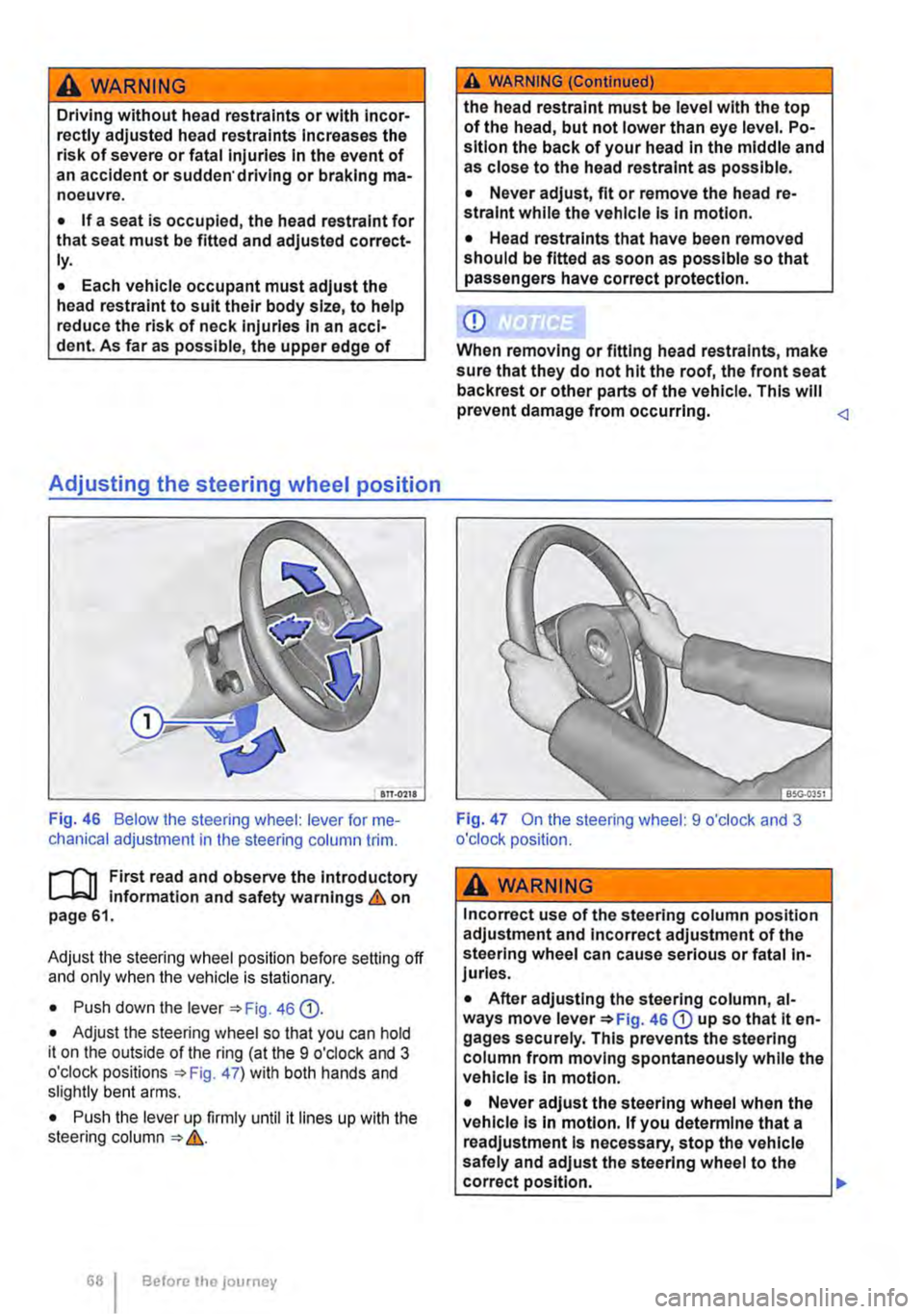
Fig. 46 Below the steering wheel: lever for me-chanical adjustment in the steering column trim.
r--f'n First read and observe the introductory L-W.I information and safety warnings & on page 61.
Adjust the steering wheel position before setting off and only when the vehicle is stationary.
• Push down the lever 46 Q).
• Adjust the steering wheel so that you can hold it on the outside of the ring (at the 9 o'clock and 3 o'clock positions =:o Fig. 47) with both hands and slightly bent arms.
• Push the lever up firmly until it lines up with the steering column =:o &.
Before the journey
A WARNING (Continued)
the head restraint must be level with the top of the head, but not lower than eye level. Po-sition the back of your head in the middle and as close to the head restraint as possible.
• Never adjust, fit or remove the head re-straint while the vehicle is in motion.
• Head restraints that have been removed should be fitted as soon as possible so that passengers have correct protection.
CD
When removing or fitting head restraints, make sure that they do not hit the roof, the front seat back rest or other parts of the vehicle. This will prevent damage from occurring.
A WARNING
Incorrect use of the steering column position adjustment and Incorrect adjustment of the steering wheel can cause serious or fatal In-juries.
• After adjusting the steering column, al-ways move lever =:oFig. 46 CD up so that it en-gages securely. This prevents the steering column from moving spontaneously while the vehicle Is In motion.
• Never adjust the steering wheel when the vehicle Is In motion. If you determine that a readjustment Is necessary, stop the vehicle safely and adjust the steering wheel to the correct position. .,.
Page 77 of 486
Bed extension (multi-flex board)
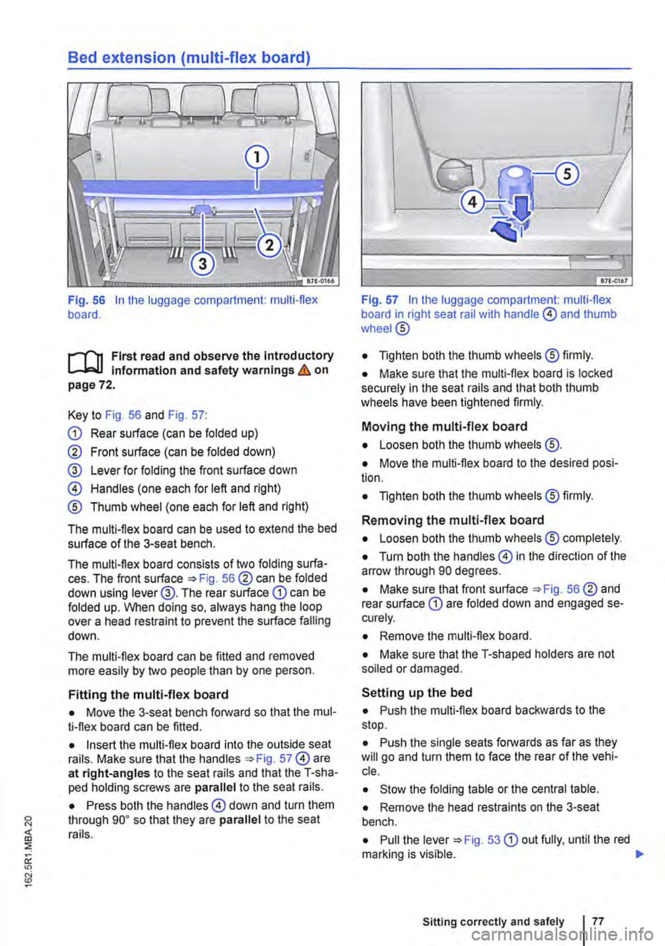
Fig. 56 In the luggage compartment: multi-flex board.
.--m First read and observe the Introductory L-.J,..U lnfonmatlon and safety warnings & on page 72.
Key to Fig. 56 and Fig. 57:
CD Rear surface (can be folded up)
@ Front surface (can be folded down)
@ Lever for folding the front surface down
@ Handles (one each for left and right)
® Thumb wheel (one each for left and right)
The multi-flex board can be used to extend the bed surface of the 3-seat bench.
The multi-flex board consists of two folding surfa-ces. The front surface =>Fig. 56@ can be folded down using lever@. The rear surface CD can be folded up. When doing so, always hang the loop over a head restraint to prevent the surface falling down.
The multi-flex board can be fitted and removed more easily by two people than by one person.
Fitting the multi-flex board
• Move the 3-seat bench forward so that the mul-ti-flex board can be fitted.
• Insert the multi-flex board into the outside seat rails. Make sure that the handles =>Fig. 57@ are at right-angles to the seat rails and that the T-sha-ped holding screws are parallel to the seat rails.
• Press both the handles@ down and turn them through go• so that they are parallel to the seat rails.
Fig. 57 In the luggage compartment: multi-flex board in right seat rail with handle @ and thumb wheel@
• Tighten both the thumb wheels® firmly.
• Make sure that the multi-flex board is locked securely in the seat rails and that both thumb wheels have been tightened firmly.
Moving the multi-flex board
• Loosen both the thumb wheels @.
• Move the multi-flex board to the desired posi-tion.
• Tighten both the thumb wheels® firmly.
Removing the multi-flex board
• Loosen both the thumb wheels® completely.
• Turn both the handles@ in the direction of the arrow through 90 degrees.
• Make sure that front surface =>Fig. 56@ and rear surface CD are folded down and engaged se-curely.
• Remove the multi-flex board.
• Make sure that the T-shaped holders are not soiled or damaged.
Setting up the bed
• Push the multi-flex board backwards to the stop.
• Push the single seats forwards as far as they will go and turn them to face the rear of the vehi-cle.
• Stow the folding table or the central table.
• Remove the head restraints on the 3-seat bench.
• Pull the lever =>Fig. 53 CD out fully, until the red marking is visible. 11>
Sitting correctly and safely
Page 81 of 486
Frontal collisions and the laws of physics
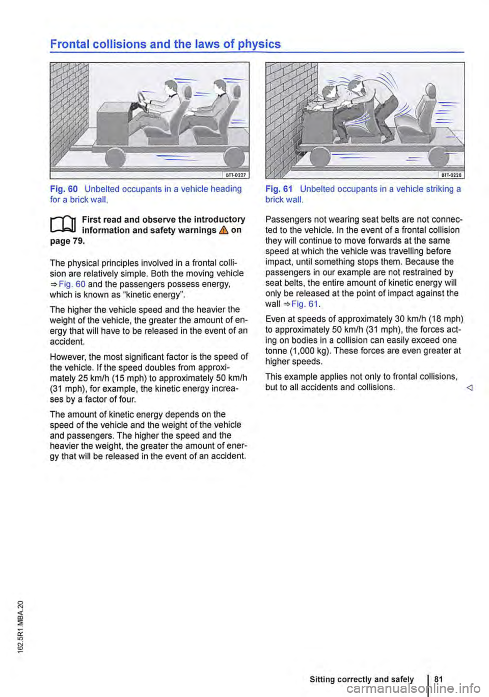
Fig. 60 Unbelted occupants in a vehicle heading for a brick wall.
r"'''"'n First read and observe the introductory information and safety warnings & on page 79.
The physical principles involved in a frontal colli-sion are relatively simple. Both the moving vehicle =>Fig. 60 and the passengers possess energy, which is known as "kinetic energy".
The higher the vehicle speed and the heavier the weight of the vehicle, the greater the amount of en-ergy that will have to be released in the event of an accident.
However, the most significant factor is the speed of the vehicle. If the speed doubles from approxi-mately 25 km/h (15 m ph) to approximately 50 km/h (31 mph), for example, the kinetic energy increa-ses by a factor of four.
The amount of kinetic energy depends on the speed of the vehicle and the weight of the vehicle and passengers. The higher the speed and the heavier the weight, the greater the amount of ener-gy that will be released in the event of an accident.
Fig. 61 Unbelted occupants in a vehicle striking a brick wall.
Passengers not wearing seat belts are not connec-ted to the vehicle. In the event of a frontal collision they will continue to move forwards at the same speed at which the vehicle was travelling before impact, until something stops them. Because the passengers in our example are not restrained by seat belts, the entire amount of kinetic energy will only be released at the point of impact against the wall =>Fig. 61.
Even at speeds of approximately 30 km/h (18 mph) to approximately 50 km/h (31 mph), the forces act-ing on bodies in a collision can easily exceed one tonne (1 ,000 kg). These forces are even greater at higher speeds.
This example applies not only to frontal collisions, but to all accidents and collisions.
Page 107 of 486
Lit up Possible cause Solution
Main beam is switched on or the headlight 107. flasher is being operated.
Main beam assist (light Assist) is activated. 110.
Several warning and indicator lamps will light up briefly as a funclional check when the ignition is switched on. They will go out after a few seconds.
Indicator lamps in light switch
Lit up Possible cause
The automatic headlight control and, if applicable, the daytime headlights or daytime running Jl lights are switched on 108 .
.fD The fog light is switched on 108.
I) I The side lights are switched on 108.
A WARNING
Failure to observe illuminated warning lamps and text messages can lead to your vehicle breaking down in traffic, and can cause acci-dent and serious injury.
• Never Ignore any illuminated warning lamps or text messages.
• Stop the vehicle as soon as possible and when safe to do so.
• Stop the vehicle at a safe distance away from moving traffic and so that no part of the exhaust system can come into contact with any inflammable material underneath the ve-hicle, e.g. dry grass, fuel, oil etc.
Turn signal and main beam lever
A WARNING (Continued)
• Any broken-down vehicle poses an In-creased accident risk both for you and for other road users. If the situation requires, switch on the hazard warning lights and set up the warning triangle as a warning to other road users.
CD
Failure to observe illuminated indicator lamps and text messages can lead to your vehicle be-ing damaged.
...--r'l1 First read and observe the introductory l.-Jo:JJ information and safety warnings & on page 106.
Move the lever into the required position:
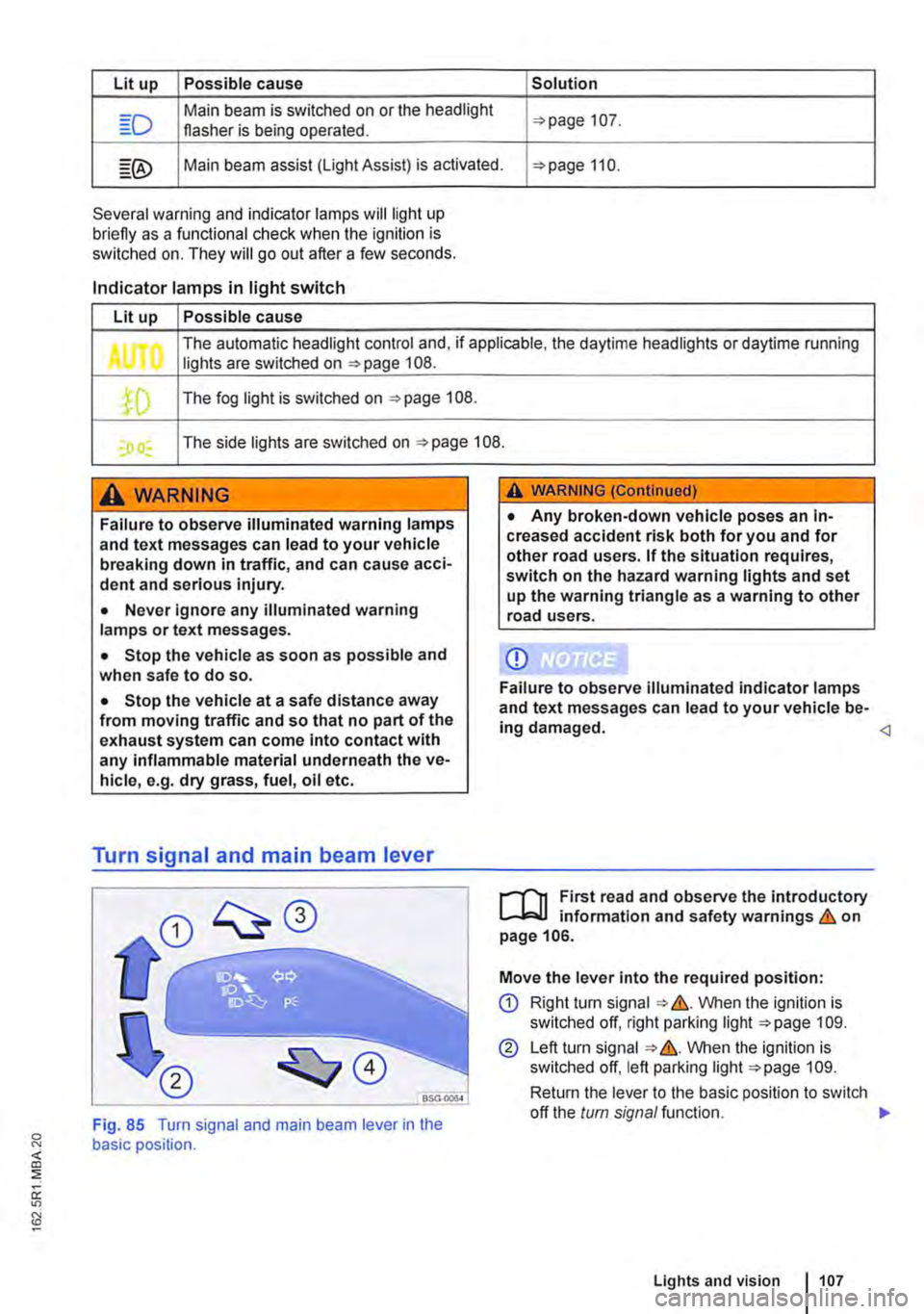
CD Right tu m signal &. VVhen the ignition is switched off, right parking light 109.
@ Left turn signal &. VVhen the ignition is switched off, left parking light 109.
Return the lever to the basic position to switch
<]
Fig. 85 Turn signal and main beam lever in the basic position.
off the turn signal function. 1>
Lights and vision 1107
Page 109 of 486

Turn the light switch to the required position 86:
When the Ignition Is switched off
0 The fog lights, dipped beam headlights and side lights are switched off.
,. The orientation lighting can be switched on.
) , The side lights are switched on.
Dipped beam headlights are switched off.
"'D While the vehicle key is in lhe ignition lock, the side lights will stay on.
Fog lights
The indicator lamps or 0$ in the light switch or Instrument cluster indicate that the fog lights are switched on.
• To switch the fog light on, pull the light switch out of the position "" or tD to the first stop.
• To switch the rear fog light 0$ on, pull the light switch out of position ,.,, or gD as far as it will go.
• To switch the fog lights off, press the light switch or move it to position 0.
Signal tones if lights are not switched off
If the key is removed from the ignition lock and the driver door is opened, a signal tone will sound in any of the following situations. This will remind you to switch off the lights as necessary.
Lights and vision -functions
1""1'11 First read and observe the introductory L-lo:.U Information and safety warnings & on page 106.
Parking light
When the parking lights (left and right turn signals) are switched on, the headlight on the correspond-ing side of the vehicle lights up along with the tail light and parts of the tail light cluster. The parking light only lights up when the Ignition is switched off and if the turn signal and main beam lever was in the central position before being operated.
Side lights
If the light switch is in position ;.o; both headlights with side lights light up, along with parts of the rear light cluster, the number plate lighting, the instru-ment cluster lighting and the buttons in the centre console and the dash panel.
If the charge level of the battery is too low, the side lights will switch off automatically &. This pre-vents the vehicle battery from being discharged
When the Ignition Is switched on
Lights switched off or daytime headlights are switched on.
The automatic headlight control and, if applica-ble, the daytime headlights are switched on.
The side lights are switched on.
The dipped beam headlights are switched on.
• If the parking light is switched on 107.
• If the light switch is in position '"'·
• If the light switch is in position iD or 0$ 112.
A WARNING
The side lights or daytime running lights are not bright enough to Illuminate the road ahead and to ensure that other road users are able to see you.
• Always switch the dipped beam head-lights on if it is dark, raining or visibility Is
completely and thus allows for still starting the en-gine 366, Automatic switch-off for electri-cal consumers.
Daytime running lights
There are separate lights in the headlights for the daytime running lights.
Only the separate lights light up when the daytime running lights are switched on &.
The daytime running lights are switched on when the ignition is switched on if the light switch is in position 0 or AUTO.
If the light switch is in position AUTO, a rain sensor will switch the dipped beam and the lighting in the instruments and switches on and off automatically.
The daytime running lights cannot be switched on or off manually. ,._
Lights and vision 1109