Page 208 of 456
208
Supra Owner's Manual3-1. CONTROLS
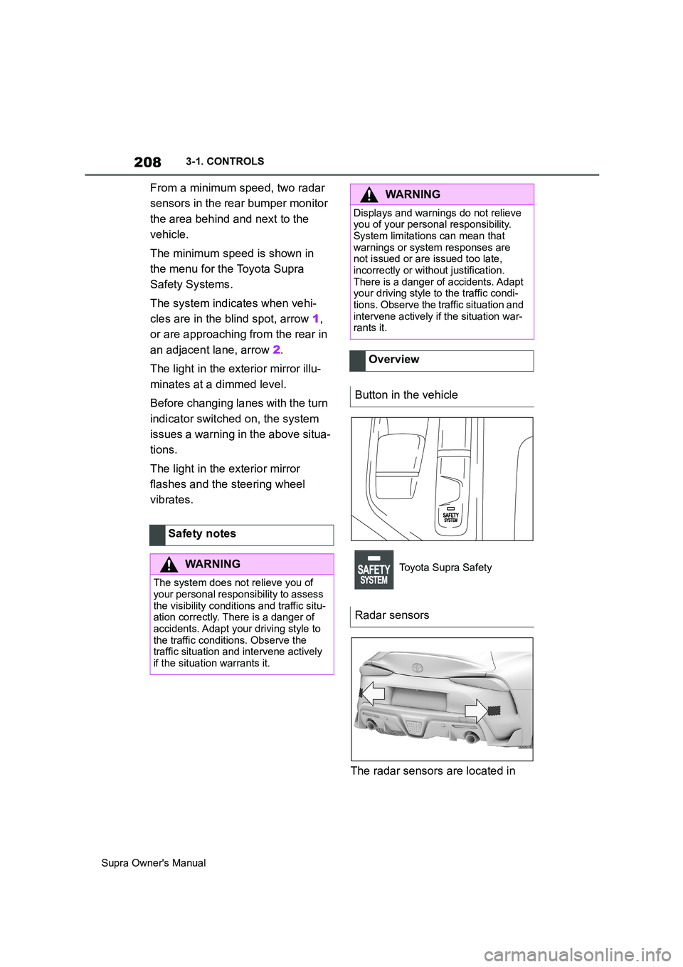
From a minimum speed, two radar
sensors in the rear bumper monitor
the area behind and next to the
vehicle.
The minimum speed is shown in
the menu for the Toyota Supra
Safety Systems.
The system indicates when vehi-
cles are in the blind spot, arrow 1,
or are approaching from the rear in
an adjacent lane, arrow 2.
The light in the exterior mirror illu-
minates at a dimmed level.
Before changing lanes with the turn
indicator switched on, the system
issues a warning in the above situa-
tions.
The light in the exterior mirror
flashes and the steering wheel
vibrates.
The radar sensors are located in Safety notes
WARNING
The system does not relieve you of
your personal responsibility to assess
the visibility conditions and traffic situ-
ation correctly. There is a danger of
accidents. Adapt your driving style to
the traffic conditions. Observe the
traffic situation and intervene actively
if the situation warrants it.
WARNING
Displays and warnings do not relieve
you of your personal responsibility.
System limitations can mean that
warnings or system responses are
not issued or are issued too late,
incorrectly or without justification.
There is a danger of accidents. Adapt
your driving style to the traffic condi-
tions. Observe the traffic situation and
intervene actively if the situation war-
rants it.
Overview
Button in the vehicle
Toyota Supra Safety
Radar sensors
Page 210 of 456
210
Supra Owner's Manual3-1. CONTROLS
4"Blind spot monitor"
5Select the desired setting.
"Off": no warning is output for this set-
ting.
The setting is saved for the cur-
rently used driver profile.
Via Toyota Supra Command:
1"My Vehicle"
2"Vehicle settings"
3"Steering wheel vibration"
4Select the desired setting.
The setting is accepted for all
Toyota Supra Safety Systems and
saved for the currently used driver
profile.
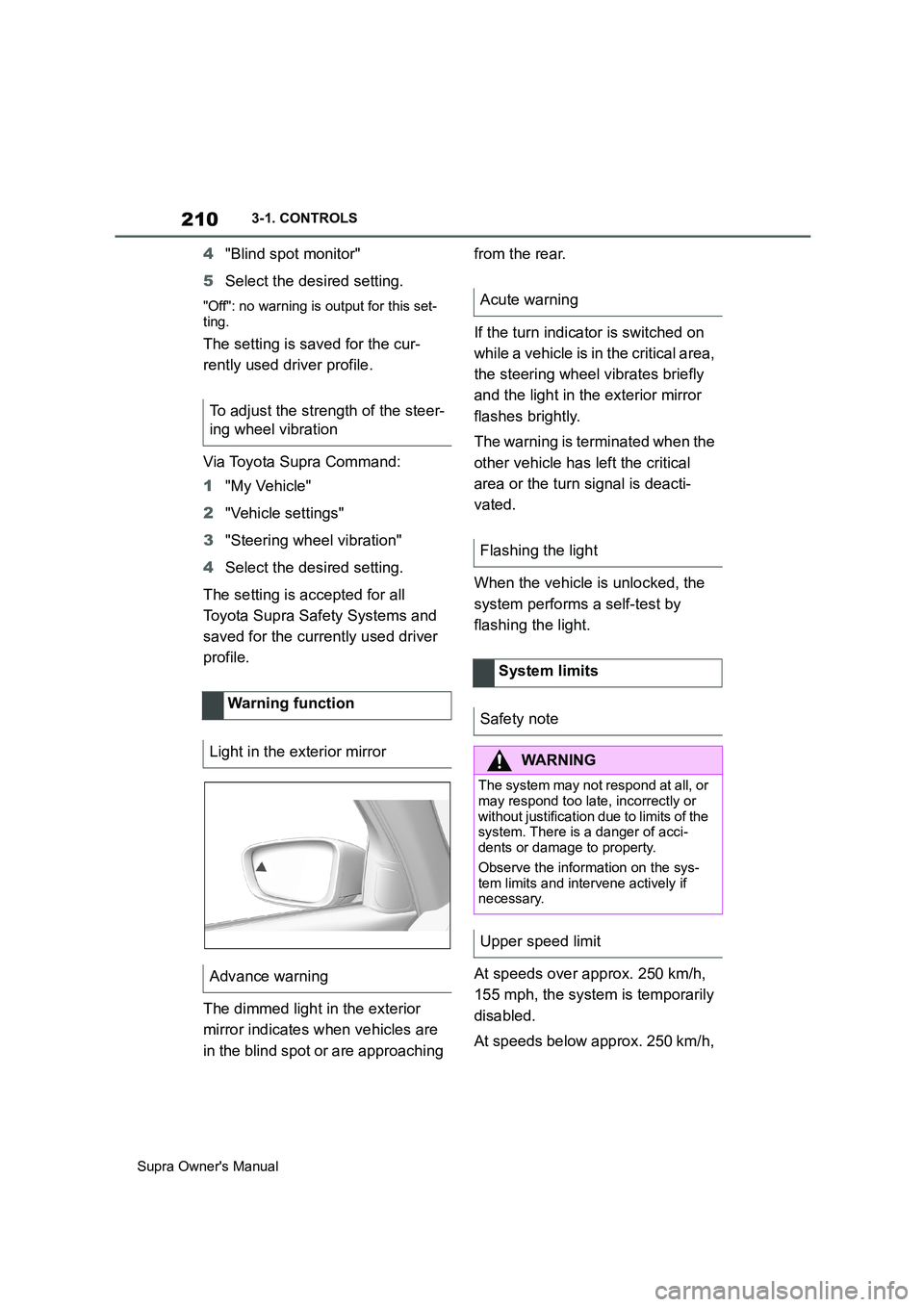
The dimmed light in the exterior
mirror indicates when vehicles are
in the blind spot or are approaching from the rear.
If the turn indicator is switched on
while a vehicle is in the critical area,
the steering wheel vibrates briefly
and the light in the exterior mirror
flashes brightly.
The warning is terminated when the
other vehicle has left the critical
area or the turn signal is deacti-
vated.
When the vehicle is unlocked, the
system performs a self-test by
flashing the light.
At speeds over approx. 250 km/h,
155 mph, the system is temporarily
disabled.
At speeds below approx. 250 km/h, To adjust the strength of the steer-
ing wheel vibration
Warning function
Light in the exterior mirror
Advance warning
Acute warning
Flashing the light
System limits
Safety note
WARNING
The system may not respond at all, or
may respond too late, incorrectly or
without justification due to limits of the
system. There is a danger of acci-
dents or damage to property.
Observe the information on the sys-
tem limits and intervene actively if
necessary.
Upper speed limit
Page 225 of 456
225
3
Supra Owner's Manual3-1. CONTROLS
CONTROLS
saved speed is not excessively
large. Otherwise, there may be
inadvertent braking or acceleration.
Cruise Control is resumed with the
saved values.
The saved speed value is deleted
and can no longer be called up in
the following instances:
When the system is switched off.
When drive-ready state is
switched off.
With the corresponding equipment,
the set speed limit is displayed digi-
tally for a short time.
Some information from the system
can also be shown in the Head-Up
Display.The desired speed is also main-
tained on a downhill stretch. The
vehicle may drive slower than the
desired speed on uphill gradients if
the engine power is not sufficient.
This system allows you to set a
desired speed and a desired dis-
tance from the vehicle in front,
using the buttons on the steering
wheel.
When the road ahead is clear, the
system maintains the desired
speed by braking or accelerating
the vehicle automatically, as
required.
If there is a vehicle driving in front,
the system adapts your own vehicle
speed in order to maintain the set
distance from the vehicle ahead.
The speed is adapted as far as the
given situation allows.
A radar sensor is fitted in the front
bumper and a camera on the
rear-view mirror for detecting vehi-
While the system is inter-
rupted, press the button.
Displays in the instrument
cluster
Indicator lamp
Green indicator lamp: the
system is active.
Grey indicator lamp: the
system is interrupted.
No indicator lamp: the sys-
tem is switched off.
Status display
Displays in the Head-Up Dis-
play
The symbol is displayed
when the desired speed set
has been reached.
System limits
Adaptive Cruise Control
with Stop & Go ACC
Principle
General
Page 227 of 456
227
3
Supra Owner's Manual3-1. CONTROLS
CONTROLS
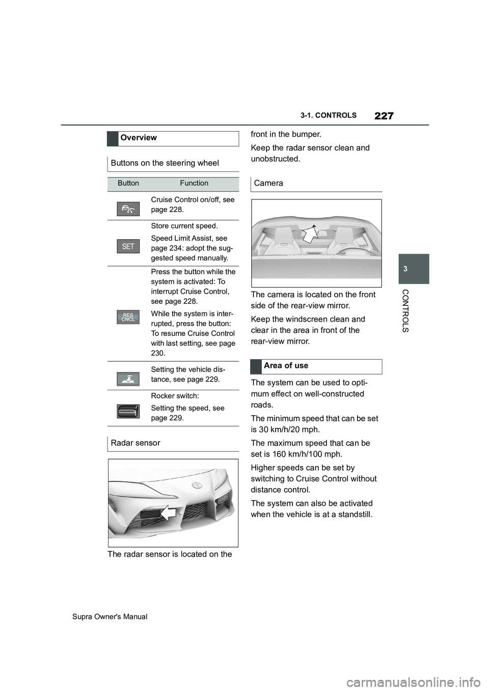
The radar sensor is located on the front in the bumper.
Keep the radar sensor clean and
unobstructed.
The camera is located on the front
side of the rear-view mirror.
Keep the windscreen clean and
clear in the area in front of the
rear-view mirror.
The system can be used to opti-
mum effect on well-constructed
roads.
The minimum speed that can be set
is 30 km/h/20 mph.
The maximum speed that can be
set is 160 km/h/100 mph.
Higher speeds can be set by
switching to Cruise Control without
distance control.
The system can also be activated
when the vehicle is at a standstill. Overview
Buttons on the steering wheel
ButtonFunction
Cruise Control on/off, see
page 228.
Store current speed.
Speed Limit Assist, see
page 234: adopt the sug-
gested speed manually.
Press the button while the
system is activated: To
interrupt Cruise Control,
see page 228.
While the system is inter-
rupted, press the button:
To resume Cruise Control
with last setting, see page
230.
Setting the vehicle dis-
tance, see page 229.
Rocker switch:
Setting the speed, see
page 229.
Radar sensor
Camera
Area of use
Page 247 of 456
247
3
Supra Owner's Manual3-1. CONTROLS
CONTROLS
2Tilt the Controller to the right.
3"Settings"
4"Cross-traffic alert"
5"Cross-traffic alert"
Or via Toyota Supra Command:
1"My vehicle"
2"Vehicle settings"
3"Parking"
4"Cross-traffic alert"
5"Cross-traffic alert"
If the system was activated on the
Control Display, it is switched on
automatically as soon as Parking
Sensors or Panorama View is
active and a gear is engaged.
The system is switched on at the
rear when reverse gear is engaged.
The system switches off automati-
cally in the following situations:
If walking speed is exceeded.
When a certain distance is
exceeded.
During active parking with the
Park Assistant.
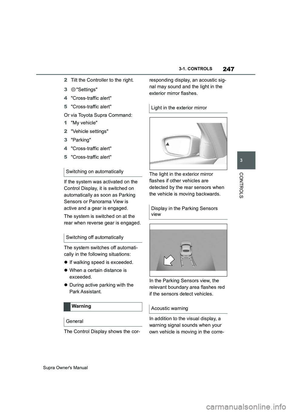
The Control Display shows the cor-responding display, an acoustic sig-
nal may sound and the light in the
exterior mirror flashes.
The light in the exterior mirror
flashes if other vehicles are
detected by the rear sensors when
the vehicle is moving backwards.
In the Parking Sensors view, the
relevant boundary area flashes red
if the sensors detect vehicles.
In addition to the visual display, a
warning signal sounds when your
own vehicle is moving in the corre- Switching on automatically
Switching off automatically
Wa rning
General
Light in the exterior mirror
Display in the Parking Sensors
view
Acoustic warning
Page 257 of 456
257
3
Supra Owner's Manual3-1. CONTROLS
CONTROLS
■Via Toyota Supra Command
1"My vehicle"
2"Vehicle settings"
3"Climate comfort"
4"Auxiliary ventilation"
5Select the required departure
time.
6Setting the departure time.
7Select the day of the week if
necessary.
■Operating requirements
If a departure time is to control
when the independent ventilation is
switched on, the relevant depar-
ture time must be activated first.
■Via Toyota Supra Command
1"My vehicle"
2"Vehicle settings"
3"Climate comfort"
4"Auxiliary ventilation"
5"For departure time"
6Activate the required departure
time.
The symbol on the climate dis-
play signals that a departure time
has been activated.This chapter describes all standard,
country-specific and special equip-
ment available for the model series.
It may therefore describe equip-
ment and functions which are not
installed in your vehicle, for exam-
ple on account of the optional
equipment selected or the country
specification. This also applies to
safety-relevant functions and sys-
tems. Please comply with the rele-
vant laws and regulations when
using the corresponding functions
and systems.
Fold the sun visor downwards or
upwards.
A vanity mirror is situated in the sun
visor behind a cover. The mirror
light switches on when the cover is
opened.
The cigarette lighter attachment
can be used as a socket for electri- Setting the departure time
Activating the departure time
Display
Interior equipment
Vehicle equipment
Sun visor
Glare protection
Vanity mirror
Power sockets
Principle
Page 332 of 456
332
Supra Owner's Manual5-1. MOBILITY
SymbolMeaning
VSC Vehicle Stability Con-
tro lSystem
Parking brake
Air conditioning
Defrost the windscreen and
remove condensation
Blower motor, Interior venti-
lation
Rear window heating
Seat heating
Seat setting
Crash-security module
Switching center column,
Light switch element, steer-
ing Operating panel Audio
HiFi amplifier, Video module
TV
Rear-view mirror
Overhead function center,
Exterior door handle elec-
tronics
Instrument cluster
Additional battery: Dual
Accumulator System (DSS)
Fuel pump control electron-
ics, Natural Vacuum Leak
Detection, Gas generator for
battery safety terminal,
Remote control receiver
Electric window opener
Heating and air-condition-
ing system
Vehicle's diagnostic port
(interface)
Interior lights in the boot
Vertical Dynamic platform
Vertical Dynamic platform
Vertical Dynamic platform
Mono Camera (Kafas)
Head Unit
Active Sound Design
USB Hub
Body Domain Controller
SymbolMeaning
Page 333 of 456
333
5
Supra Owner's Manual5-1. MOBILITY
MOBILITY
This chapter describes all standard,
country-specific and special equip-
ment available for the model series.
It may therefore describe equip-
ment and functions which are not
installed in your vehicle, for exam-
ple on account of the optional
equipment selected or the country
specification. This also applies to
safety-relevant functions and sys-
tems. Please comply with the rele-
vant laws and regulations when
using the corresponding functions
and systems.
Controller (Toyota Supra
Command)
Electric fan (air cooler), Con-
trolled differential lock
12 V socket, Cigarette
lighter
Interior lights in the boot
Door lock, Exterior door
handle electronics, Telem-
atic Communication Box
Electronic gear box control
Telematic Communication
Box, Exterior door handle
electronics
Electric fan, Rear Power dis-
tributor
Engine control
Switching center column,
Light switch element, Body
Domain Controller
Control panels centre con-
sole, Interior light in the
glove box, Interior light, Inte-
rior light in the sunvisor,
Exterior mirror, Selector
lever
Telematic Communication
Box, Exterior door handle
electronics passenger side
Switcher block driver's door,
Exterior mirror
SymbolMeaningBreakdown Assist
Vehicle equipment
If a malfunction occurs
while driving
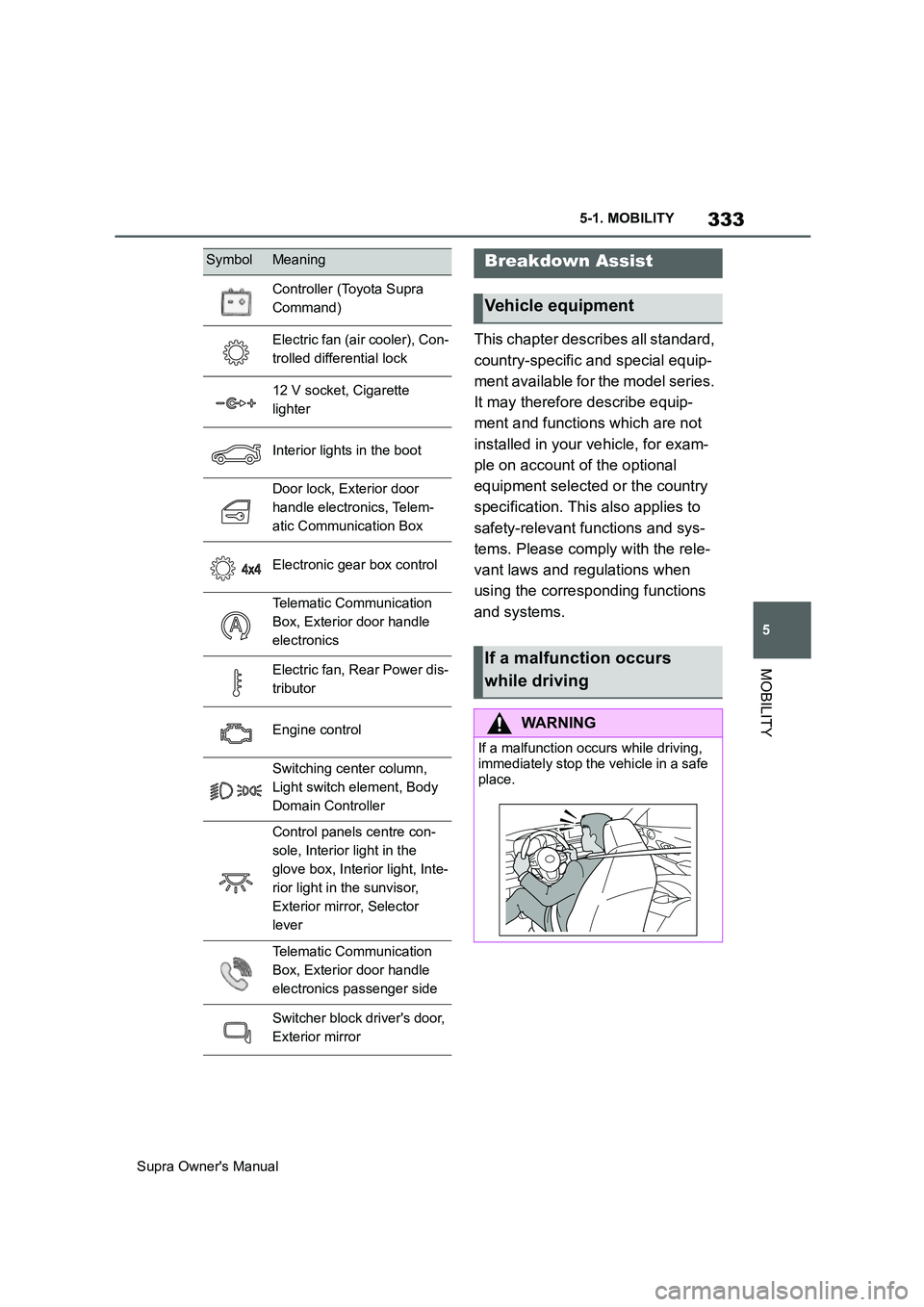
WARNING
If a malfunction occurs while driving,
immediately stop the vehicle in a safe
place.