Page 217 of 348
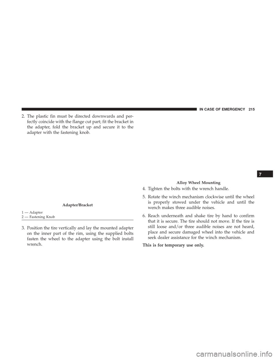
2. The plastic fin must be directed downwards and per-fectly coincide with the flange cut part; fit the bracket in
the adapter, fold the bracket up and secure it to the
adapter with the fastening knob.
3. Position the tire vertically and lay the mounted adapter on the inner part of the rim, using the supplied bolts
fasten the wheel to the adapter using the bolt install
wrench. 4. Tighten the bolts with the wrench handle.
5. Rotate the winch mechanism clockwise until the wheel
is properly stowed under the vehicle and until the
wench makes three audible noises.
6. Reach underneath and shake tire by hand to confirm that it is secure. The tire should not move. If the tire is
still loose and/or three audible noises are not heard,
place and secure damaged wheel into the vehicle and
seek dealer assistance for the winch mechanism.
This is for temporary use only.
Adapter/Bracket
1 — Adapter
2 — Fastening Knob
Alloy Wheel Mounting
7
IN CASE OF EMERGENCY 215
Page 218 of 348

Vehicles Equipped With Wheel Covers
1. Mount the road tire on the axle.
2. To ease the installation process for steel wheels withwheel covers, install two wheel bolts on the wheel.
Install the wheel bolts with the threaded end of the bolt
toward the wheel. Lightly tighten the wheel bolts. 3. Align the valve notch in the wheel cover with the valve
stem on the wheel. Install the cover by hand, snapping
the cover over the two wheel bolts. Do not use a
hammer or excessive force to install the cover.
4. Install the remaining wheel bolts with the threaded end of the wheel bolt toward the wheel. Lightly tighten the
wheel bolts.
WARNING!
To avoid the risk of forcing the vehicle off the jack, do
not fully tighten the wheel bolts until the vehicle has
been lowered. Failure to follow this warning may
result in serious injury.
5. Lower the vehicle to the ground by turning the jack handle counterclockwise.
6. Finish tightening the wheel bolts. Push down on the wrench while holding at the end of the handle for
increased leverage. Tighten the wheel bolts in a star
pattern until each wheel bolt has been tightened twice.
Refer to “Torque Specifications” in “Technical Specifica-
tions” for correct wheel bolt torque.
Tire And Wheel Cover Or Center Cap
1 — Valve Stem 4 — Wheel Cover
2 — Valve Notch 5 — Road Wheel
3 — Wheel Bolt 216 IN CASE OF EMERGENCY
Page 219 of 348

7. After 25 miles (40 km) check the wheel bolt torque witha torque wrench to ensure that all wheel bolts are
properly seated against the wheel.
TIRE SERVICE KIT — IF EQUIPPED
Small punctures up to ¼” (6 mm) in the tire tread can be
sealed with Tire Service Kit. Foreign objects (e.g., screws or
nails) should not be removed from the tire. Tire Service Kit
can be used in outside temperatures down to approxi-
mately -4°F (-20°C).
This kit will provide a temporary tire seal, allowing you to
drive your vehicle up to 100 miles (160 km) with a
maximum speed of 50 mph (80 km/h).
Tire Service Kit Storage
The Tire Service Kit is located under the passenger seat.
Tire Service Kit Usage
If a tire is punctured, you can make a first emergency repair
using the Tire Service Kit located under the passenger seat.
Tire punctures of up to 1/4” (6 mm) can be repaired; the kit
can be used in all weather conditions. Do not remove the
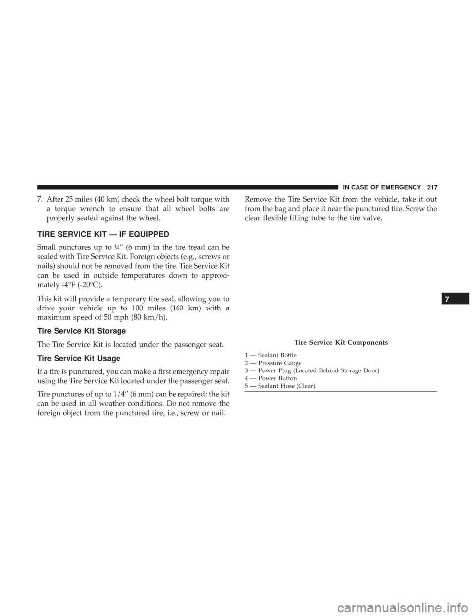
foreign object from the punctured tire, i.e., screw or nail. Remove the Tire Service Kit from the vehicle, take it out
from the bag and place it near the punctured tire. Screw the
clear flexible filling tube to the tire valve.
Tire Service Kit Components
1 — Sealant Bottle
2 — Pressure Gauge
3 — Power Plug (Located Behind Storage Door)
4 — Power Button
5 — Sealant Hose (Clear)
7
IN CASE OF EMERGENCY 217
Page 220 of 348

WARNING!
•Do not attempt to seal a tire on the side of the vehicle
closest to traffic. Pull far enough off the road to avoid
the danger of being hit when using the Tire Service
Kit.
• Do not use Tire Service Kit or drive the vehicle under
the following circumstances:
– If the puncture in the tire tread is approximately 1/4 inch (6 mm) or larger.
– If the tire has any sidewall damage.
– If the tire has any damage from driving with extremely low tire pressure.
– If the tire has any damage from driving on a flat tire.
– If the wheel has any damage.
– If you are unsure of the condition of the tire or the wheel.
• Keep Tire Service Kit away from open flames or heat
source.
• A loose Tire Service Kit thrown forward in a collision
or hard stop could endanger the occupants of the
vehicle. Always stow the Tire Service Kit in the place
provided. Failure to follow these warnings can result
(Continued)
WARNING! (Continued)
in injuries that are serious or fatal to you, your
passengers, and others around you.
• Take care not to allow the contents of Tire Service Kit
to come in contact with hair, eyes, or clothing. Tire
Service Kit sealant is harmful if inhaled, swallowed,
or absorbed through the skin. It causes skin, eye, and
respiratory irritation. Flush immediately with plenty
of water if there is any contact with eyes or skin.
Change clothing as soon as possible, if there is any
contact with clothing.
• Tire Service Kit Sealant solution contains latex. In
case of an allergic reaction or rash, consult a physi-
cian immediately. Keep Tire Service Kit out of reach
of children. If swallowed, rinse mouth immediately
with plenty of water and drink plenty of water. Do
not induce vomiting! Consult a physician immedi-
ately.
Insert the power plug into the vehicle power outlet socket.
Start the vehicle engine.
Push the Tire Service Kit power button to the “I” position.
The electric compressor will be turned on, sealant and air
will inflate the tire.
218 IN CASE OF EMERGENCY
Page 221 of 348

Minimum 26 psi (1.8 bar) of pressure should be reached
within 20 minutes. If the pressure has not been reached,
turn off and remove the Tire Service Kit, drive the vehicle
30 feet (10 meters) back and forth, to better distribute the
sealant inside the tire.
Attach the clear flexible filling tube of the compressor
directly to the tire valve and repeat the inflation process.
When the correct pressure has been reached, start driving
the vehicle to uniformly distribute the sealant inside the
tire. After 10 minutes, stop and check the tire pressure. If
the pressure is below 19 psi (1.3 bar), do not drive the
vehicle, as the tire is too damaged, contact the nearest
authorized dealer.
WARNING!
Tire Service Kit is not a permanent flat tire repair. Have
the tire inspected and repaired or replaced after using
Tire Service Kit. Do not exceed 50 mph (80 km/h) until
the tire is repaired or replaced. Failure to follow this
warning can result in injuries that are serious or fatal
to you, your passengers, and others around you. Have
the tire checked as soon as possible at an authorized
dealer.If the pressure is at 19 psi (1.3 bar) or above repeat the
inflation process to reach the correct tire pressure and
continue driving.
Peel off the warning label from the bottle and place it on
the dashboard as a reminder to the driver that a tire has
been treated with Tire Service Kit.
WARNING!
The metal end fitting from Power Plug may get hot
after use, so it should be handled carefully.
NOTE: Replace the sealant canister prior to the expiration
date at your authorized dealer.
7
IN CASE OF EMERGENCY 219
Page 222 of 348

WARNING!
Store the sealant canister in its special compartment,
away from sources of heat. Failure to follow this
WARNING may result in sealant canister rupture and
serious injury or death.
JUMP STARTING
If your vehicle has a discharged battery, it can be jump
started using a set of jumper cables and a battery in another
vehicle or by using a portable battery booster pack. Jumpstarting can be dangerous if done improperly, so please
follow the procedures in this section carefully.
NOTE:
When using a portable battery booster pack, follow
the manufacturer ’s operating instructions and precautions.
WARNING!
Do not attempt jump starting if the battery is frozen. It
could rupture or explode and cause personal injury.
CAUTION!
Do not use a portable battery booster pack or any other
booster source with a system voltage greater than 12
Volts or damage to the battery, starter motor, alternator
or electrical system may occur.
Preparations For Jump Starting
The battery in your vehicle is located in the front of the
engine compartment, behind the left headlight assembly.
NOTE: The positive battery post is covered with a protec-
tive cap. Lift up on the cap to gain access to the positive
battery post.
Tire Service Kit Expiration Date Location
220 IN CASE OF EMERGENCY
Page 223 of 348

WARNING!
•Take care to avoid the radiator cooling fan whenever
the hood is raised. It can start anytime the ignition
switch is ON. You can be injured by moving fan
blades.
• Remove any metal jewelry such as rings, watch
bands and bracelets that could make an inadvertent
electrical contact. You could be seriously injured.
(Continued)
WARNING! (Continued)
•Batteries contain sulfuric acid that can burn your
skin or eyes and generate hydrogen gas which is
flammable and explosive. Keep open flames or
sparks away from the battery.
1. Apply the parking brake, shift the automatic transmis- sion into PARK and turn the ignition to LOCK.
2. Turn off the heater, radio, and all unnecessary electrical accessories.
3. If using another vehicle to jump-start the battery, park the vehicle within the jumper cables reach, apply the
parking brake and make sure the ignition is OFF.
WARNING!
Do not allow vehicles to touch each other as this could
establish a ground connection and personal injury
could result.
Positive Battery Post Location
7
IN CASE OF EMERGENCY 221
Page 224 of 348

Jump Starting Procedure
WARNING!
Failure to follow this jump starting procedure could
result in personal injury or property damage due to
battery explosion.
CAUTION!
Failure to follow these procedures could result in
damage to the charging system of the booster vehicle
or the discharged vehicle.
Connecting The Jumper Cables
1. Connect the positive (+)end of the jumper cable to the
positive (+)post of the discharged vehicle.
2. Connect the opposite end of the positive (+)jumper
cable to the positive (+)post of the booster battery.
3. Connect the negative (-)end of the jumper cable to the
negative (-)post of the booster battery.
4. Connect the opposite end of the negative (-)jumper
cable to a good engine ground (exposed metal part of the discharged vehicle’s engine) away from the battery
and the fuel injection system.
WARNING!
Do not connect the jumper cable to the negative (-) post
of the discharged battery. The resulting electrical spark
could cause the battery to explode and could result in
personal injury. Only use the specific ground point, do
not use any other exposed metal parts.
5. Start the engine in the vehicle that has the booster battery, let the engine idle a few minutes, and then start
the engine in the vehicle with the discharged battery.
6. Once the engine is started, remove the jumper cables in the reverse sequence:
Disconnecting The Jumper Cables
1. Disconnect the negative (-)end of the jumper cable from
the engine ground of the vehicle with the discharged
battery.
2. Disconnect the opposite end of the negative (-)jumper
cable from the negative (-)post of the booster battery.
3. Disconnect the positive (+)end of the jumper cable from
the positive (+)post of the booster battery.
222 IN CASE OF EMERGENCY