Page 176 of 610
1. TRIP RESET switch for twin trip odom-eter (P. 2-6)
— Instrument brightness control switch
(P. 2-58)
2. Headlight, fog light (if so equipped) and turn signal switch
— Headlight (P. 2-53)
— Turn signal light (P. 2-53)
— Fog light (if so equipped) (P. 2-53)
3. Steering-wheel-mounted controls (lef t side)
— Audio control (P. 4-3, 4-46)
— Vehicle information display controls
(P. 2-28)
4. Steering wheel — Power steering system (P. 5-146)
— Horn (P. 2-60)
— Driver's supplemental air bag (P. 1-43)
5. Wiper and washer switch (P. 2-50)
6. Steering-wheel-mounted controls (right side)
— Cruise control switches (if so
equipped) (P. 5-54)
— Intelligent Cruise Control (ICC)
switches (if so equipped) (P. 5-56)
— ProPILOT Assist switch (if so equipped)
(P. 5-80)
COCKPIT
Instruments and controls2-3
Page 179 of 610
1. Vehicle information display (P. 2-28)— Clock (P. 2-13)
— Outside air temperature (P. 2-13)
— Li-ion battery available charge gauge
(P. 2-10)
— Driving range (P. 2-10)
— Odometer/twin trip odometer (P. 2-7)
— Indicator for timer (P. CH-44)
— Power meter (P. 2-9)
2. Warning and indicator lights (P. 2-15) — Turn signal/Hazard indicator light
(P. 2-53)
— READY to drive indicator light (P. 2-26)
— ECO mode indicator (P. 2-14)
3. Speedometer (P. 2-7)
METERS AND GAUGES
2-6Instruments and controls
Page 180 of 610
SPEEDOMETER AND ODOMETER
The vehicle is equipped with a speedom-
eter and odometer. The speedometer is
located on the right side of the vehicle in-
formation display. The odometer is located
within the vehicle information display.
Speedometer
The speedometer indicates the vehicle
speed.
Odometer/twin trip odometer
The odometer and twin trip odometer�2
are displayed on the vehicle information
display when the power switch is in the ON
or READY to drive position.
The odometer records the total distance
the vehicle has been driven.
The twin trip odometer records the dis-
tance of individual trips.
Instruments and controls2-7
Page 181 of 610

Changing the display:
Pushing the TRIP RESET switch
�1located
on the lef t side of the combination meter
panel changes the display as follows:
Odometer →TRIP A →TRIP B →Odometer
For additional information about the ve-
hicle information display, refer to “Vehicle
information display” in this section.
Resetting the trip odometer:
Pushing the TRIP RESET switch
�1for ap-
proximately 1 second resets the currently
displayed trip odometer to zero.
LI-ION BATTERY TEMPERATURE
GAUGE
The gauge indicates the temperature of
the Li-ion battery.
The temperature of the Li-ion battery is
within the normal range when the display
is within the zone
�1shown in the illustra-
tion.
The temperature of the Li-ion battery var-
ies according to the outside air tempera-
ture and driving conditions.
NOTE:
• If the display indicates that the tem-
perature of the Li-ion battery is near the
red zone end of the normal range, re-
duce vehicle speed to decrease the
temperature. If the indicator is over the
normal range, the power provided to
the traction motor is reduced when the
power limitation indicator light is illumi-
nated. Therefore, the vehicle is not as
responsive when the accelerator is de-
pressed while the power limitation light
is illuminated. For additional informa-
tion, refer to “Power limitation indicator
light” in this section.
• If the outside temperature is extremely
low, the Li-ion temperature gauge may
not display a temperature reading. The
vehicle may not be able to be put in the
READY to drive mode. Have the system
checked. It is recommended that you
visit a NISSAN certified LEAF dealer for
this service.
2-8Instruments and controls
Page 182 of 610

POWER METER
This meter displays the actual traction mo-
tor power consumption
�Aand the regen-
erative brake power provided to the Li-ion
battery
�B.
The power meter is in a neutral state
�3.
The white illuminated portion
�1in the dis-
play moves right or lef t depending on de-
mand.
The white illuminated portion
�1moves to
the right when power is provided to the
traction motor (Li-ion battery discharges). The white illuminated portion
�1moves to
the lef t when power is generated and pro-
vided to the Li-ion battery by the regenera-
tive brake system (Li-ion battery charging).
The power meter also indicates if the
power provided to the motor is limited or
if regenerative braking is limited. When
power or regenerative braking is limited,
the illuminated segments on the display
are narrowed
�2.
Regenerative braking is automatically re-
duced when the Li-ion battery is fully
charged to prevent the Li-ion battery from
becoming overcharged. Regenerative brak- ing is also automatically reduced when the
Li-ion battery temperature is high/low (indi-
cated by the red/blue zones on the Li-ion
battery temperature gauge) to prevent Li-
ion battery damage.
The more regenerative braking is reduced,
the more illuminated segments on the dis-
play are narrowed
�2.
If the Li-ion battery charge is low, power
provided to the traction motor is reduced.
Motor output is also limited if the Li-ion
battery temperature is high/low (indicated
by the red/blue zones on the Li-ion battery
temperature gauge) or the Li-ion battery
charge level is low.
The more power provided to the traction
motor is reduced, the more illuminated
segments on the display are narrowed
�2.
NOTE:
If the power meter is selected on the
trip computer, the meter is not dis-
played.
Instruments and controls
2-9
Page 183 of 610

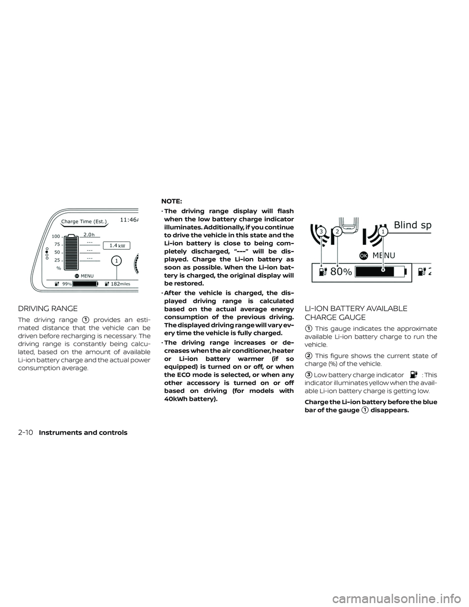
DRIVING RANGE
The driving range�1provides an esti-
mated distance that the vehicle can be
driven before recharging is necessary. The
driving range is constantly being calcu-
lated, based on the amount of available
Li-ion battery charge and the actual power
consumption average.
NOTE:
• The driving range display will flash
when the low battery charge indicator
illuminates. Additionally, if you continue
to drive the vehicle in this state and the
Li-ion battery is close to being com-
pletely discharged, “---” will be dis-
played. Charge the Li-ion battery as
soon as possible. When the Li-ion bat-
tery is charged, the original display will
be restored.
• Af ter the vehicle is charged, the dis-
played driving range is calculated
based on the actual average energy
consumption of the previous driving.
The displayed driving range will vary ev-
ery time the vehicle is fully charged.
• The driving range increases or de-
creases when the air conditioner, heater
or Li-ion battery warmer (if so
equipped) is turned on or off, or when
the ECO mode is selected, or when any
other accessory is turned on or off
based on driving (for models with
40kWh battery).
LI-ION BATTERY AVAILABLE
CHARGE GAUGE
�1This gauge indicates the approximate
available Li-ion battery charge to run the
vehicle.
�2This figure shows the current state of
charge (%) of the vehicle.
�3Low battery charge indicator: This
indicator illuminates yellow when the avail-
able Li-ion battery charge is getting low.
Charge the Li-ion battery before the blue
bar of the gauge
�1disappears.
2-10Instruments and controls
Page 184 of 610

The low battery charge indicator�3
illuminates yellow when the available Li-ion
battery charge is getting low. Charge as
soon as it is convenient, preferably before
the blue bar of the gauge
�1disappears.
When the blue bar of the gauge
�1disap-
pears and the charge indicator
�3
illuminates, there is a very small reserve of
Li-ion battery charge remaining.
NOTE:
• The length of the blue bar of the gauge
�1is determined by the available
charge and the amount of charge the
Li-ion battery is capable of storing at
the current temperature.
• Temperature affects the amount of
charge the Li-ion battery is capable of
storing. The Li-ion battery is capable of
storing less power when the Li-ion bat-
tery temperature is cold. The Li-ion bat-
tery is capable of storing more power
when the Li-ion battery temperature is
warm. The length of the blue bar of the
gauge
�1can change based on the
amount of power the Li-ion battery is
capable of storing. For example, when
the Li-ion battery becomes colder, a longer blue bar of the gauge
�1illumi-
nates because the available charge is a
greater percentage of the Li-ion bat-
tery's capability of storing power. When
the Li-ion battery becomes warmer, a
shorter blue bar of the gauge
�1illumi-
nates because the remaining energy
is a lower percentage of the Li-ion bat-
tery's capability of storing power.
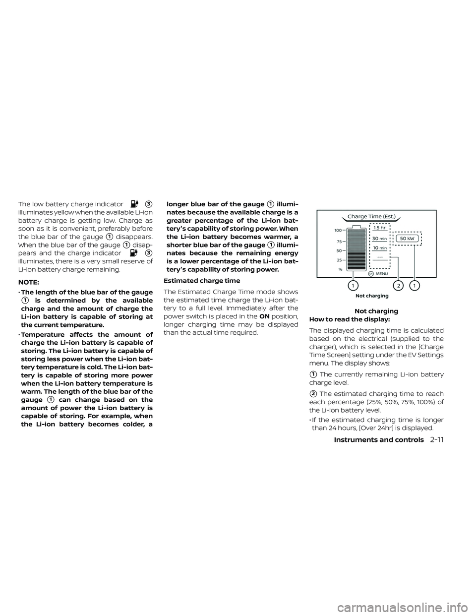
Estimated charge time
The Estimated Charge Time mode shows
the estimated time charge the Li-ion bat-
tery to a full level. Immediately af ter the
power switch is placed in the ONposition,
longer charging time may be displayed
than the actual time required. How to read the display:
The displayed charging time is calculated
based on the electrical (supplied to the
charger), which is selected in the [Charge
Time Screen] setting under the EV Settings
menu. The display shows:
�1The currently remaining Li-ion battery
charge level.
�2The estimated charging time to reach
each percentage (25%, 50%, 75%, 100%) of
the Li-ion battery level.
• If the estimated charging time is longer than 24 hours, [Over 24hr] is displayed. Not charging
Instruments and controls2-11
Page 185 of 610
![NISSAN LEAF 2019 Owner´s Manual • When the currently remaining Li-ion bat-tery level exceeds each percentage level,
the charging time will be displayed as [---].
• When the Li-ion battery was fully charge, all the charging time NISSAN LEAF 2019 Owner´s Manual • When the currently remaining Li-ion bat-tery level exceeds each percentage level,
the charging time will be displayed as [---].
• When the Li-ion battery was fully charge, all the charging time](/manual-img/5/40306/w960_40306-184.png)
• When the currently remaining Li-ion bat-tery level exceeds each percentage level,
the charging time will be displayed as [---].
• When the Li-ion battery was fully charge, all the charging time information will be
displayed as [---].
�3The currently selected electrical power
(supplied to the charger).
�4The estimated charge level of the Li-ion
battery to be reached when the remaining
charging time has passed.
�5The remaining charging time before the
quick charger is shut off.
�6The electrical power that is actually sup-
plied while quick charging.
When charging is not performed, pushing
the button on the steering wheel will
switch the display to the [Charge Time
Screen]. Select the electrical power that
you wish to show in the Estimated Charge
Time display.
NOTE:
• While charging, the estimated charging
time is calculated based on the electri-
cal power that is currently being sup-
plied to the charger.
•
The electrical power for the normal
charging is displayed at a fixed value.
Therefore, the displayed electrical power
may differ from the one that is actually
supplied.
• For the quick charging, the electrical
power display will change to the actual
electrical power while charging. If the
charging is stopped or the power sup-
ply is stopped (unplugged, etc.), the dis-
played electrical power returns to the
selected electrical power.
• The displayed charging time on each
percentage level is the current estima-
tion, and the actual charging time will
vary depending on the conditions of the
vehicle or the state of charge.
• Right af ter starting of stopping charge,
the estimated charging time may differ
from the actual charging time. The ac-
tual charging time will be displayed
af ter a period of time.
While charging (quick charge
[if so equipped])
2-12Instruments and controls