2019 MERCEDES-BENZ SPRINTER radio
[x] Cancel search: radioPage 217 of 354
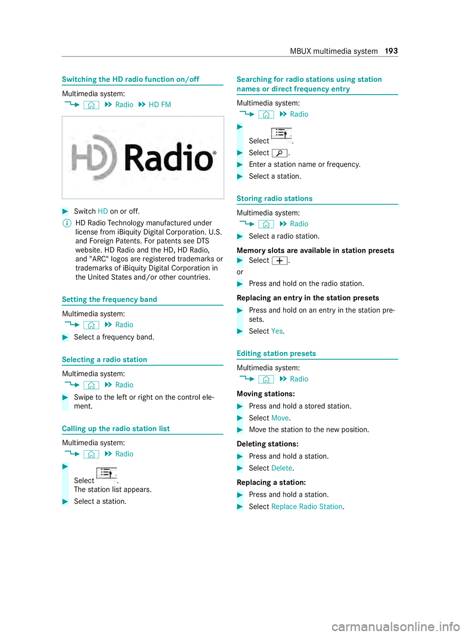
Switching
the HD radio function on/o ff Multimedia sy
stem:
4 © 5
Radio 5
HD FM #
Switch HDon or off.
% HD
Radio Tech nology manu factured under
license from iBi quity Digital Corporation. U.S.
and Foreign Patents. For patents see DTS
we bsite. HD Radio and the HD, HD Radio,
and "ARC" logos are regis tere d trademar ksor
trademar ksof iBiquity Digital Corporation in
th e United States and/or other countries. Setting
the frequency band Multimedia sy
stem:
4 © 5
Radio #
Select a frequency band. Selecting a
radio station Multimedia sy
stem:
4 © 5
Radio #
Swipe tothe left or right on the cont rol ele‐
ment. Calling up
thera dio station list Multimedia sy
stem:
4 © 5
Radio #
Select .
The station list appears. #
Select a station. Sear
ching forra dio stations using station
names or direct frequency entry Multimedia sy
stem:
4 © 5
Radio #
Select .
#
Select 00D3. #
Ente r astation name or frequenc y. #
Select a station. St
oring radio stations Multimedia sy
stem:
4 © 5
Radio #
Select a radio station.
Memory slots are available in station presets #
Select 0081.
or #
Press and hold on thera dio station.
Re placing an entry in the station presets #
Press and hold on an entry in thest ation pre‐
sets. #
Select Yes. Editing
station presets Multimedia sy
stem:
4 © 5
Radio
Moving stations: #
Press and hold a stored station. #
Select Move. #
Movethest ation tothe new position.
Deleting stations: #
Press and hold a station. #
Select Delete.
Re placing a station: #
Press and hold a station. #
Select Replace Radio Station . MBUX multimedia sy
stem 19 3
Page 218 of 354
Showing accident
reports Multimedia sy
stem:
4 © 5
Radio 5
Z
% The
availability of the function is dependent
on the count ry. #
Switch Display Emergency Warnings on or
off. Displaying
radio text Multimedia sy
stem:
4 © 5
Radio 5
Z #
Switch Display Radio Text Information on or
off. Sound
Sound settings
Information about
the sound sy stem
The sound sy stem is available for all functions in
th era dio and media modes. The settings, for
ex ample forth e equalizer, ef fect the playback of
all media sources.
Calling up the sound menu
Multimedia sy stem:
4 © 5
Media 5
Z 5
Sound
The following functions are available:
R Equalizer
R Balance and Fader
R Autom. Volume Adjustment #
Select a sound menu.
Ad justing treble, mid-range and bass settings
Multimedia sy stem:
4 © 5
Media 5
Z 5
Sound #
Set TREBLE, MIDorBASS .
Ac tivating/deactivating automatic volume
adjustment
Multimedia sy stem:
4 © 5
Media 5
Z 5
Sound
Au tomatic volume adjustment compensates for
dif fering volumes when changing between audio
sources. #
Swit chAutom. Volume Adjustment on or off.
Ad justing the balance/ fader
The availability of this function depends on the
ve hicle equipment. Multimedia sy
stem:
4 © 5
Media 5
Z 5
Sound #
Adjust the balance and fader. 194
MBUX multimedia sy stem
Page 264 of 354
Make sure
toobser vethefo llowing fur ther rela‐
te d subject:
R Notes on tire pressure (/ page 234)
Rest arting the tire pressure monitor
Requ irements:
R The recommended tire pressure is cor rectly
set forth ere spective operating condition on
each of the wheels (/ page 234).
R Re
start the tire pressure monitoring sys‐
te m in the following situations:
- The tire pressure has changed.
- The wheels or tires ha vebeen changed or
newly ins talled.
On-board computer: 4 Service 5
Tires #
Scroll down in the menu.
The Use Current Pressures as New Refer-
ence Values message appears in the multi‐
function displa y. #
Con firm the message toinitiate a restart.
The Tire Press. Monitor Restarted message
appears in the multifunction displa y.
Cur rent wa rning messages are dele ted and
th e0077 yellow warning lamp goes out.
Af teryo u ha vedriven for a few minutes, the
sy stem checks whe ther the cur rent tire pres‐
su res are within the specified range. The cur‐
re nt tire pressures are then accep ted as ref‐
erence values and monitored.
Make sure toobser vethefo llowing fur ther rela‐
te d subject:
R Notes on tire pressure (/ page 234) Ra
dio-equipment appr oval of the tire pres‐
sure monitoring sy stem
Ra dio equipment appr oval numbers Countr
yRadio equipment appr oval
number
Canada IC: 4008C- TSSRE4A
Ope ration is subject tothefo llow‐
ing two conditions:
(1) this device may not cause
harmful inter fere nce, and
(2) this device must acce ptany
inter fere nce received, including
inter fere nce that may cause
undesired operation.
Mexic oM odel:TSSRE4A & TSSSG4G6,
IFETEL: RLVHUTS17-0806
US AF CC ID:YGOTSSRE4A
This device complies wi th Part15
of the FCC Rules. Operation is
subject tothefo llowing two con‐
ditions: (1) this device may not
cause harmful inter fere nce, and
(2) this device must acce ptany
inter fere nce received, including
inter fere nce that may cause
undesired operation.
WA RNING: Any changes or modi fi‐
cation not expressly appr ovedby
th e party responsible for compli‐
ance could void the user's author‐
ity tooperate this equipment. Loading the
vehicle Ti
re and Loading Information placard &
WARNING Risk of an accident when driv‐
ing wi than ove rloaded tire
Overloaded tires may overheat and bur stas a
consequence. Overloaded tires can also
impair thesteering and handling characteris‐
tics and lead tobrake failure. #
Obser vethe load rating of the tires. #
The load rating mu stbe at least half the
gross axleweight rating of theve hicle.
Mercedes-Benz recommends you use
th e load-bearing index, which is given in
th eve hicle documents. 240
Wheels and tires
Page 284 of 354

Information on
technical data
The given data only applies tovehicles with
st andard equipment. Further information can be
obtained at a qualified specialist workshop. On-board electronics
Note
s onworkon the engine electronics *
NO
TES Premature wearthro ugh
improper main tenance Improper maintenance may cause
vehicle
components towe ar more quickly and the
ve hicle's operating permit may be in validated. #
Always ha vewo rkon the engine elec‐
tronics and related components car ried
out at a qualified specialist workshop. Tw
o-w ayradios In
stallation no tesfo r two-w ayradios &
WARNING Risk of accident due to
improper workon two-w ayradios
The electromagnetic radiation from two-w ay
ra dios can inter fere with the on-board elec‐
tronics if RF transmit ters are manipulated or
re trofitted inco rrectl y.
This could jeopardize the operating saf ety of
th eve hicle. #
You should ha veall workon electrical
and electronic components car ried out
at a qualified specialist workshop. &
WARNING Risk of accident from incor‐
re ct ope ration of two-w ayradios
If yo u operate two- wayra dios incor rectly in
th eve hicle, the electromagnetic radiation
could inter fere with the on-board electronics,
e.g.:
R ifth e two-w ayradio is not connected to
an exterior antenna
R ifth eex terior antenna is not cor rectly
mounted or is not of low reflection
This could jeopardies the operating saf ety of
th eve hicle. #
Have the lo w-reflection exterior antenna
ins talled at a qualified specialist work‐
shop. #
When operating two-w ayradios in the
ve hicle, alw ays connect them tothe
lo w- reflection exterior antenna. *
NO
TEInva lidation of the operating per‐
mit due tofailure tocomply wi th the
instructions for ins tallation and use The operating permit may be in
validated if the
instructions for ins tallation and use of two-
wa yra dios are not obser ved. #
Only use appr oved frequency bands. #
Obser vethe maximum permissible out‐
put po wer in these frequency bands. #
Only use appr oved antenna positions. Use
Tech nical Specification ISO/TS 21609 (Road
Ve hicles - EMC guidelines for ins tallation of af ter‐
mar ketra dio frequency transmitting equipment)
when retrofitting two-w ayradios. Comply with the
legal requirements for de tach able parts.
If yo ur vehicle has ins talling for two-w ayradio
equipment, use the po wer supp lyor antenna con‐
nections intended for use with the ins talling.
Obser vethe manufacturer's supplement during
ins tallation.
Information on two-w ayradio transmission
output
The maximum transmission outputs (PEAK) at the
base of the antenna must not exceed theva lues
in thefo llowing table:
Fr equency band and maximum transmission
output Fr
equency band Maximum transmis‐
sion output
Sho rtwa ve
3 — 54MHz 10
0 W
4 — m — waveband
74 — 88 MHz 30 W
2 — m — waveband
14 4 — 174 MHz 50 W
Tr unked radio sys‐
te m/T etra
380 — 460 MHz 10 W260
Tech nical da ta
Page 285 of 354
Fr
equency band Maximum transmis‐
sion output
70 — cm — waveband
420 — 450 MHz 35 W
Tw o-w ayradio
(2G/3G/4G) 10 WThe
following can be used in theve hicle without
re strictions:
R two-w ayradios with a maximum transmission
output of up to100 mW
R two-w ayradios with transmit ter frequencies
in the 380 – 410 MHz frequency band and a
maximum transmission output of up to2 W
(trunked radio sy stem/T etra)
R mobile phones (2G/3G/4G)
There are no restrictions when positioning the
antenna on the outside of theve hicle forth efo l‐
lowing frequency bands:
R Trunked radio sy stem/T etra
R 70 — cm — waveband
R 2G/3G/4G Ve
hicle identi fication pla te,ve hicle identi fi‐
cation number (VIN) and engine number
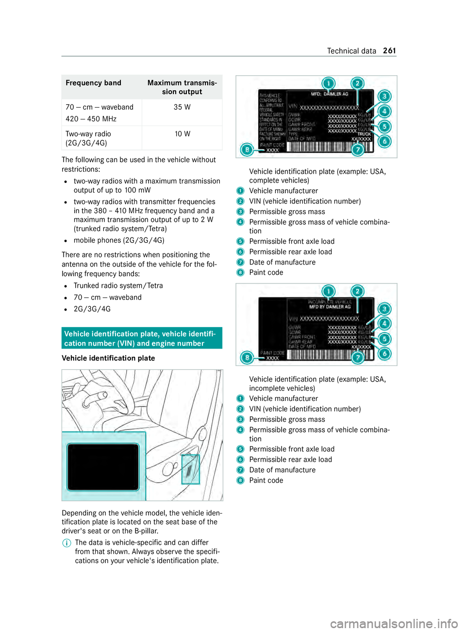
Ve hicle identi fication pla te Depending on
theve hicle model, theve hicle iden‐
tification plate is located on the seat base of the
driver's seat or on the B-pillar.
% The data is
vehicle-specific and can dif fer
from that shown. Alw ays obser vethe specifi‐
cations on your vehicle's identification plate. Ve
hicle identification plate (e xample: US A,
comple te vehicles)
1 Vehicle manufacturer
2 VIN (vehicle identification number)
3 Perm issible gross mass
4 Perm issible gross mass of vehicle combina‐
tion
5 Perm issible front axle load
6 Perm issible rear axle load
7 Date of manufacture
8 Paint code Ve
hicle identification plate (e xample: US A,
incomple te vehicles)
1 Vehicle manufacturer
2 VIN (vehicle identification number)
3 Perm issible gross mass
4 Perm issible gross mass of vehicle combina‐
tion
5 Perm issible front axle load
6 Perm issible rear axle load
7 Date of manufacture
8 Paint code Te
ch nical da ta261
Page 314 of 354
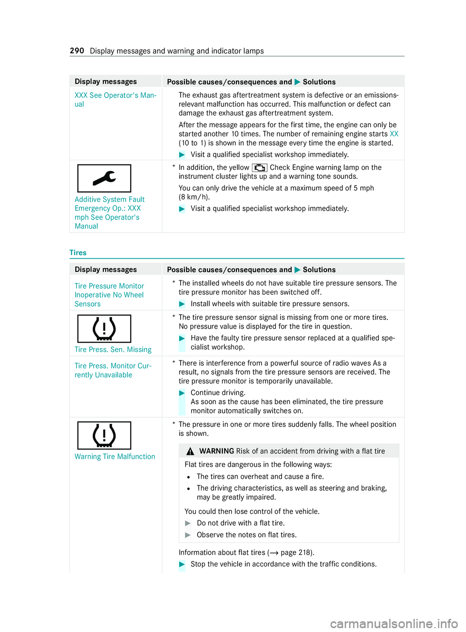
Display messages
Possible causes/consequences and 0050 0050Solutions
XXX See Operator's Man-
ual The
exhaust gas af tertre atment sy stem is defective or an emissions-
re leva nt malfunction has occu rred. This malfunction or defect can
damage theex haust gas af tertre atment sy stem.
Af terth e message appears forth efirs t time, the engine can only be
st ar ted ano ther 10 times. The number of remaining engine starts XX
(10 to1) is shown in the message everytime the engine is star ted. #
Visit a qualified specialist workshop immediately.
0099 Additive System Fault
Emergency Op.: XXX
mph See Operator's
Manual *
In addition, theye llow 00B9 Check Engine warning lamp on the
instrument clus ter lights up and a warning tone sounds.
Yo u can only drive theve hicle at a maximum speed of 5 mph
(8 km/h). #
Visit a qualified specialist workshop immediately. Ti
res Display messages
Possible causes/consequences and 0050 0050Solutions
Tire Pressure Monitor
Inoperative No Wheel
Sensors *T
he ins talled wheels do not ha vesuitable tire pressure sensors. The
tire pressure monitor has been switched off. #
Install wheels with suitable tire pressure sensors.
0077
Tire Press. Sen. Missing *T
he tire pressure sensor signal is missing from one or more tires.
No pressure value is displa yedfo rth e tire in question. #
Have thefa ulty tire pressure sensor replaced at a qualified spe‐
cialist workshop.
Tire Press. Monitor Cur-
rently Unavailable *T
here is inter fere nce from a po werful source of radio wav es As a
re sult, no signals from the tire pressure sensors are received. The
tire pressure monitor is temp orarily una vailable. #
Continue driving.
As soon as the cause has been eliminated, the tire pressure
monitor automatically switches on.
0077 Warning Tire Malfunction *T
he pressure in one or more tires suddenly falls. The wheel position
is shown. &
WARNING Risk of an accident from driving wi thaflat tire
Flat tires are dangerous in thefo llowing ways:
R The tires can overheat and cause a fire.
R The driving characteristics, as well as steering and braking,
may be greatly impaired.
Yo u could then lose cont rol of theve hicle. #
Do not drive with a flat tire. #
Obse rveth e no tes on flat tires. In
fo rm ation about flat tires (/ page218). #
Stop theve hicle in accordance with the tra ffic conditions. 290
Display messages and warning and indicator lamps
Page 316 of 354

Display messages
Possible causes/consequences and 0050 0050Solutions
Key Not Detected (red
display message) R
You cannot lock theve hicle centra lly. #
Ensure that theke y is in theve hicle.
If th eke y de tection function has a malfunction due toastro ngradio
signal source, proceed as follo ws: #
Stop theve hicle immediately, paying attention toroad and traf‐
fi c conditions. #
Place theke y in the slot forst arting with theke y (/ page104).
00AF Key No t Detected (white
display message) *T
hekey is cur rently not de tected. #
Change theke y's position in theve hicle. #
Ifth eke y is still not de tected, start the engine with theke y in
th e slot(/ page104).
00AF
Replace Key Ba ttery*T
hekey's bat tery isflat. #
Change the battery (/ page 42).
00AF
Obtain a New Key *T
hekey must be replaced. #
Visit a qualified specialist workshop. Ve
hicle Display messages
Possible causes/consequences and 0050 0050Solutions
00B2
Check Washer Fluid *W
asher fluid le vel in washer reser voir has fallen below the minimum. #
Top up washer fluid (/ page 208). *A
t least one door is open. #
Close all the doors. *T
he hood is open. &
WARNING Risk of accident if the engine hood is unlatched
while driving
An unloc ked engine hood may open up when theve hicle is in
motion and block your vie w. #
Never unlatch the engine hood while driving. #
Before every trip, ensure that the engine hood is latched. #
Stop in a safe location immediately. #
Close the hood. 292
Display messages and warning and indicator lamps
Page 334 of 354
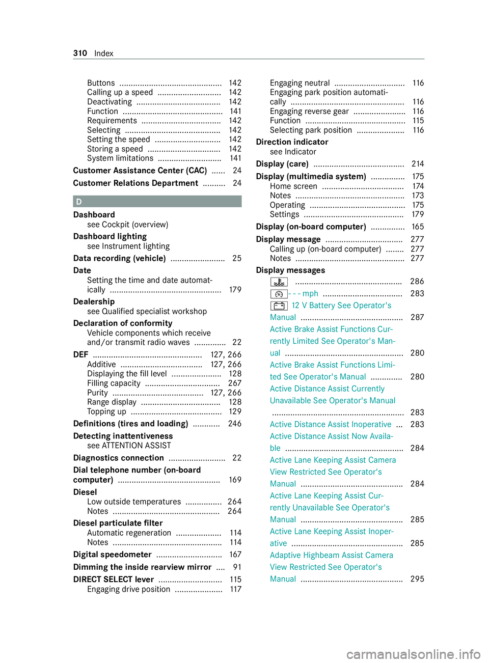
Buttons .............................................
14 2
Calling up a speed ............................ 14 2
Deactivating .................................... .142
Fu nction ............................................ 141
Re quirements .................................. .142
Selecting .......................................... 14 2
Setting the speed ............................. 14 2
St oring a speed ................................ 14 2
Sy stem limitations ............................1 41
Cus tomer Assi stance Center (C AC)...... 24
Cus tomer Relations Department ..........24 D
Dashboa rd
see Cockpit (o verview)
Dashboa rdlighting
see Instrument lighting
Data recording (vehicle) ........................ 25
Date Setting the time and date automat‐
ically .................................................1 79
Dealership see Qualified specialist workshop
Declaration of conformity Vehicle components which recei ve
and/or transmit radio wav es .............. 22
DEF ................................................ 127, 266
Ad ditive .................................... 127, 266
Displ aying thefill le vel ...................... 12 8
Filling capacity ................................. 267
Pu rity ........................................ 127, 266
Ra nge displ ay................................... 12 8
To pping up ........................................ 12 9
Definitions (ti res and loading) ............24 6
De tecting inat tentiveness
see ATTENTION ASSIST
Diagnostics connection .........................22
Dial telephone number (on-board
computer) ............................................ .169
Diesel Low outside temp eratures ................2 64
No tes ............................................... 264
Diesel particulate filter
Au tomatic rege neration .................... 11 4
No tes ................................................ 11 4
Digital speedome ter ............................. 167
Dimming the inside rearview mir ror.... 91
DIRECT SELECT le ver............................ 11 5
Engaging drive position ..................... 11 7Engaging neutral ...............................
11 6
Engaging pa rkposition automati‐
cally .................................................. 11 6
Engaging reve rsege ar ...................... .116
Fu nction ............................................ 11 5
Selecting pa rkposition .....................1 16
Direction indicator see Indicator
Display (care) ........................................ 214
Display (multimedia sy stem) .............. .175
Home screen .................................... 174
No tes ................................................ 173
Operating .......................................... 175
Settings ............................................ 17 9
Display (on-boa rdcompu ter) ............... 16 5
Display message .................................. 277
Calling up (on-board co mputer) ........ 277
No tes ................................................ 277
Display messages 00AC .............................................. .286
00B2- - - mph................................... 283
003D 12V Battery See Operator's
Manual .............................................2 87
Ac tive Brake Assi stFunctions Cur‐
re ntly Limited See Ope rator's Man‐
ual .................................................... 280
Ac tive Brake Assi stFunctions Limi‐
te d See Operator's Manual .............. 280
Ac tive Dis tance Assi stCur rently
Un available See Operator's Manual
.......................................................... 283
Ac tive Dis tance Assi stInoperative ... 283
Ac tive Dis tance Assi stNow Availa‐
ble .................................................... 284
Ac tive Lane Keeping Assist Camera
Vi ew Restricted See Ope rator's
Manual ............................................. 284
Ac tive Lane Keeping Assist Cur‐
re ntly Una vailable See Opera tor's
Manual ............................................. 285
Ac tive Lane Keeping Assist Inoper‐
ative .................................................2 85
Ad aptive Highbeam Assist Camera
Vi ew Restricted See Ope rator's
Manual ............................................. 295 310
Index