2019 MERCEDES-BENZ SPRINTER engine
[x] Cancel search: enginePage 246 of 354

#
Switch off all electrical consumers. #
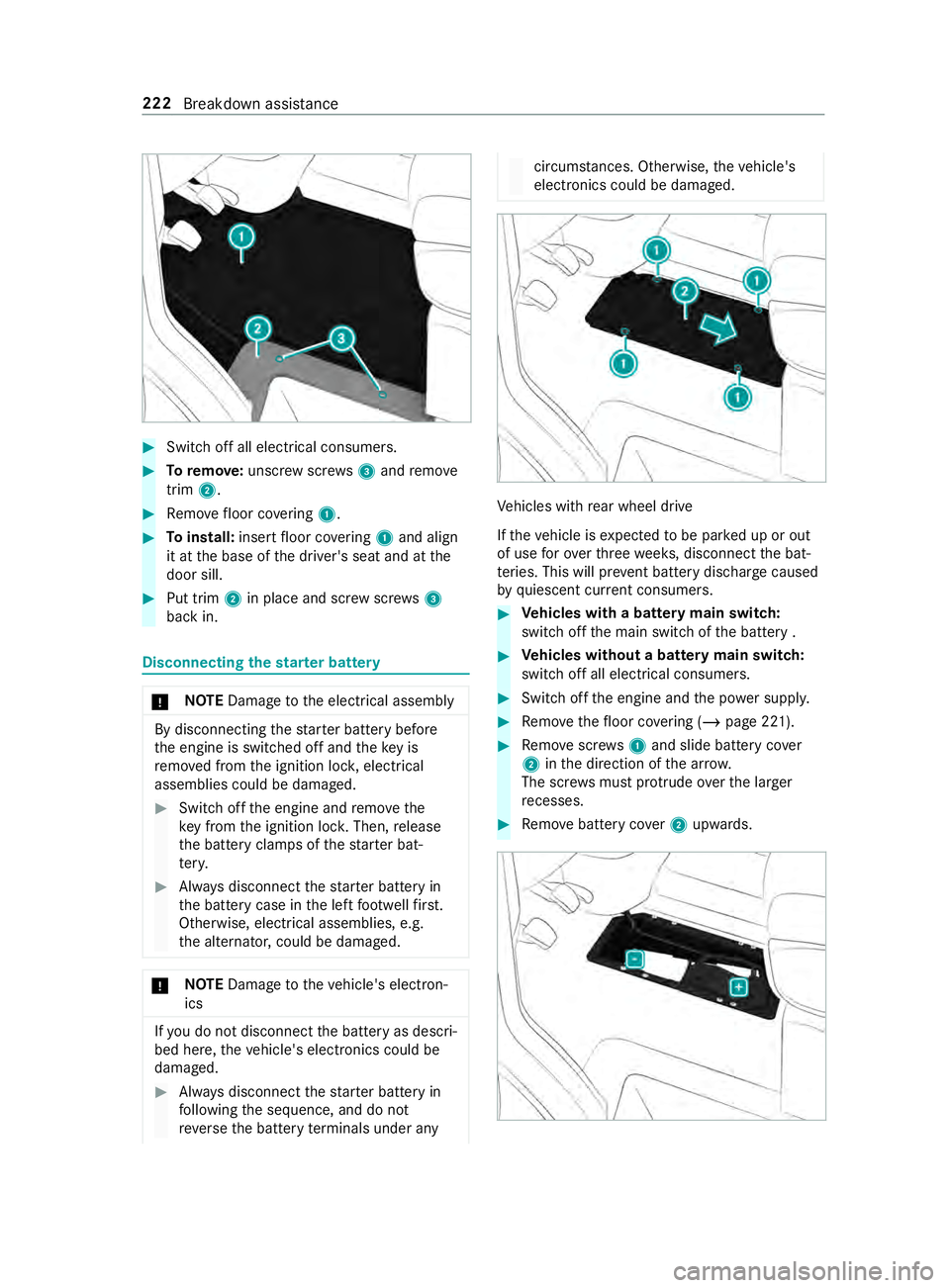
Toremo ve:unscr ewscrews3 and remo ve
trim 2. #
Remo vefloor co vering 1. #
Toinstall: insertfloor co vering 1 and align
it at the base of the driver's seat and at the
door sill. #
Put trim 2in place and scr ewscrews3
back in. Disconnecting
thest ar ter battery *
NO
TEDama getothe electrical assembly By disconnecting
thest ar ter battery before
th e engine is switched off and theke y is
re mo ved from the ignition loc k,electrical
assemblies could be damaged. #
Switch off the engine and remo vethe
ke y from the ignition loc k.Then, release
th e battery clamps of thest ar ter bat‐
te ry. #
Always disconnect thest ar ter battery in
th e battery case in the left foot we llfirs t.
Otherwise, electrical assemblies, e.g.
th e alternator, could be damaged. *
NO
TEDama getotheve hicle's electron‐
ics If
yo u do not disconnect the battery as descri‐
bed here, theve hicle's electronics could be
damaged. #
Always disconnect thest ar ter battery in
fo llowing the sequence, and do not
re ve rseth e battery term inals under any circums
tances. Otherwise, theve hicle's
electronics could be damaged. Ve
hicles with rear wheel drive
If th eve hicle is expected tobe par ked up or out
of use forove rth re ewe eks, disconnect the bat‐
te ries. This will pr event battery discharge caused
by quiescent cur rent consumers. #
Vehicles with a battery main switch:
switch off the main switch of the battery . #
Vehicles without a battery main switch:
switch off all electrical consumers. #
Switch off the engine and the po wer supp ly. #
Remo vethefloor co vering (/ page 221). #
Remo vescr ews1 and slide battery co ver
2 inthe direction of the ar row.
The scr ews must pr otru de ove rth e lar ger
re cesses. #
Remo vebattery co ver2 upwards. 222
Breakdown assi stance
Page 248 of 354

Otherwise,
gases or battery acid could
escape.
R Make sure that the de tach able parts are con‐
nec ted in the same way as before. Disconnecting
the auxiliary bat tery inthe
engine compa rtment *
NO
TEDama getothe electrical assembly By disconnecting
thest ar ter battery before
th e engine is switched off and theke y is
re mo ved from the ignition loc k,electrical
assemblies could be damaged. #
Switch off the engine and remo vethe
ke y from the ignition loc k.Then, release
th e battery clamps of thest ar ter bat‐
te ry. #
Always disconnect thest ar ter battery in
th e battery case in the left foot we llfirs t.
Otherwise, electrical assemblies, e.g.
th e alternator, could be damaged. *
NO
TEDama getotheve hicle's electron‐
ics Incor
rectly disconnecting the auxiliary battery
can cause damage totheve hicle's electron‐
ics. #
Always disconnect the auxiliary battery
as described in thefo llowing sequence.
Do not reve rseth e battery term inals
under any circums tances. #
Obser vethe saf ety measures and pr otection
notices when disconnecting the auxiliary bat‐
te ry ( / page 219). #
Swit choff all electrical consumers. #
Switch off the engine and the po wer supp ly. #
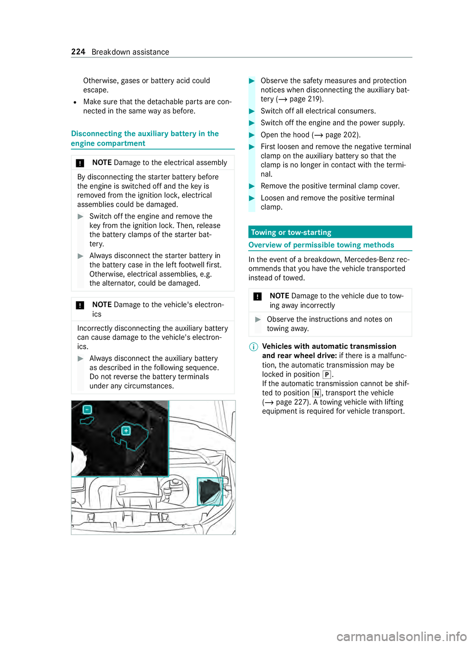
Open the hood (/ page 202). #
Firstloosen and remo vethe negative term inal
clamp on the auxiliary battery so that the
cla mp is no longer in con tact wi th thete rm i‐
nal. #
Remo vethe positive term inal clamp co ver. #
Loosen and remo vethe positive term inal
clamp. To
wing or tow- starting Overview of permissible
towing me thods In
theeve nt of a breakdown, Mercedes-Benz rec‐
ommends that you ha vetheve hicle transpor ted
ins tead of towe d.
* NO
TEDama getotheve hicle due to tow‐
ing away incor rectly #
Obser vethe instructions and no tes on
to wing away. %
Ve
hicles with automatic transmission
and rear wheel drive: ifth ere is a malfunc‐
tion, the automatic transmission may be
loc ked in position 005D.
If th e automatic transmission cann otbe shif‐
te dto position 005C, transport theve hicle
(/ page 227). A towing vehicle with lifting
equipment is requ ired forve hicle transport. 224
Breakdown assis tance
Page 249 of 354

Pe
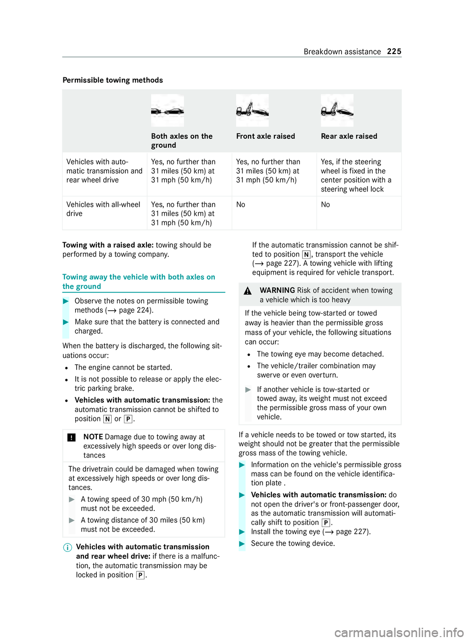
rm issible towing me thods Bo
th axles on the
gr ound Fr
ont axle raised Re
ar axle raised
Ve hicles with auto‐
matic transmission and
re ar wheel drive Ye
s, no fur ther than
31 miles (50 km) at
31 mp h (50 km/h) Ye
s, no fur ther than
31 miles (50 km) at
31 mp h (50 km/h) Ye
s, if thesteering
wheel is fixe d in the
center position wi th a
st eering wheel lock
Ve hicles with all-wheel
drive Ye
s, no fur ther than
31 miles (50 km) at
31 mp h (50 km/h) No
NoTo
wing with a raised axle: towing should be
per form ed byato wing compan y. To
wing away theve hicle with bo thaxles on
th egr ound #
Obser vethe no tes on permissible towing
me thods (/ page 224). #
Make sure that the battery is connected and
ch arge d.
When the battery is dischar ged, thefo llowing sit‐
uations occur:
R The engine cannot be star ted.
R It is not possible torelease or apply the elec‐
tric parking brake.
R Vehicles with automatic transmission: the
automatic transmission cannot be shif tedto
position 005Cor005D.
* NO
TEDama gedue to to wing away at
exc essively high speeds or over long dis‐
ta nces The driv
etra in could be damaged when towing
at exc essively high speeds or over long dis‐
ta nces. #
Atowing speed of 30 mph (50 km/h)
must not be exceeded. #
Atowing distance of 30 miles (50 km)
must not be exceeded. %
Ve
hicles with automatic transmission
and rear wheel drive: ifth ere is a malfunc‐
tion, the automatic transmission may be
loc ked in position 005D. If
th e automatic transmission cann otbe shif‐
te dto position 005C, transport theve hicle
(/ page 227). A towing vehicle with lifting
equipment is requ ired forve hicle transport. &
WARNING Risk of accident when towing
a ve hicle which is too heavy
If th eve hicle being tow- star ted or towed
aw ay is heavier than the permissible gross
mass of your vehicle, thefo llowing situations
can occur:
R The towing eye may become de tach ed.
R The vehicle/trailer combination may
swer veoreve nove rturn. #
If ano ther vehicle is tow- star ted or
to we daw ay, its weight must not exceed
th e permissible gross mass of your own
ve hicle. If a
vehicle needs tobe towe d or tow star ted, its
we ight should not be greaterth at the permissible
gross mass of theto wing vehicle. #
Information on theve hicle's permissible gross
mass can be found on theve hicle identifica‐
tion plate . #
Vehicles with automatic transmission: do
not open the driver's or front-passen ger door,
as the automatic transmission will automati‐
cally shift toposition 005D. #
Installth eto wing eye (/ page 227). #
Secure theto wing device. Breakdown assis
tance 225
Page 252 of 354

Re
ar towing eye (vehicles with passenger vehicle
appr oval)
% Re
ar towing eye2 is permanently attached
to theve hicle.
* NO
TEDama gedue toincor rect use of
th eto wing eye When a
towing eye is used toreco ver a vehi‐
cle, theve hicle may be damaged in the proc‐
ess. #
Only use theto wing eyeto to waw ay or
to w start theve hicle. To
w starting vehicle (eme rgency engine start) Ve
hicles with automatic transmission
* NO
TEDama getothe automatic trans‐
mission due to towstarting The automatic transmission may be damaged
in the process of tow starting vehicles with
automatic transmission. #
Vehicles with automatic transmission
must not be tow star ted. #
Do not tow start vehicles with automatic
transmission. Electrical fuses
Note
s on electrical fuses &
WARNING Risk of accident and injury
due toove rloaded lines
If yo u manipulate or bridge a faulty fuse or if
yo ure place it with a fuse with a higher
amperage, the electric line could be overloa‐
ded.
This could result in a fire. #
Alwaysre place faulty fuses with speci‐
fi ed new fuses containing the cor rect
amperage. *
NO
TEDama gedue toincor rect fuses Electrical components or sy
stems could be
damaged byincor rect fuses. #
Only use fuses whi chhave been
appr ovedby Mercedes-Benz and which
ha ve the cor rect fuse rating. The electrical fuses in
your vehicle switch off
defective circuits. If a fuse blo ws, all the compo‐
nents on the circuit and their functions will cease
to operate.
Blown fuses must be replaced with fuses of an
equivalent specification, which you can de ter‐
mine bythe color and fuse rating. The fuse allo‐
cation chart and fur ther information on the elec‐
tric fuses and relays can be found in the "Fuse
allocation chart" supplement.
* NO
TEDama geor malfunctions caused by
moisture Moisture may cause dama
getothe electrical
sy stem or cause it tomalfunction. #
When the fuse box is open, make sure
th at no moisture can enter the fuse box. #
When closing the fuse box, make sure
th at the seal of the lid is positioned cor‐
re ctly on the fuse box. If
th e new fuse which has been inser ted also
blo ws, ha vethe cause traced and rectified at a
qu alified specialist workshop.
Make sure of thefo llowing before replacing a
fuse:
R theve hicle is secured such that it does not
ro llaw ay
R all electrical consume rsare swit ched off 228
Breakdown assis tance
Page 275 of 354

Preparing
theve hicle for a wheel change Re
quirements:
R The tire-change tool kit is available.
R The vehicle is not on a slope.
R The vehicle is on solid, non-slippery and le vel
ground. #
Appl yth e parking brake. #
Movethe front wheels tothest ra ight-ahead
position. #
Vehicles with automatic transmission:
shift the transmission toposition 005D. #
Switch off the engine. #
Make sure that the engine cann otbe star ted. #
Take theve hicle tool kit from thefo ot we ll on
th e front passsenger side (/ page 229).Ve
hicles with rear wheel drive #
Take the jack and the tire-change tool kit out
of thestow age compartment (/ page 250).#
If necessar y,remo vethe hub cab. #
Assemble the lug wrench extension using the
middle rod and thero d with the lar gest diam‐
et er from theth re e-piece jack pump le ver. #
Starting with the middle rod, slide the lug
wrench extension as far as it will go onto the
lug wrench. #
Using the lug wrench, loosen the wheel nuts
or bolts on the wheel you wish tochange by
about one full turn. Do not unscr ewthe wheel
nuts or bolts comple tely. #
Raise theve hicle (/ page 251). Ra
ising theve hicle when changing a wheel &
WARNING Risk of inju ryfrom jack tip‐
ping
If yo u park a vehicle with air suspension, the
air suspension may remain activated for up to
one hour, even when the ignition is switched
off. If youth en raise theve hicle with the jac k,
th e air suspension will attem pttoadjust the
ve hicle le vel.
The jack may tip. #
Press the Service button on the air sus‐
pension remo tecontrol before raising
th eve hicle.
This pr events au tomatic readjustment
of theve hicle le vel and pr events it from
being raised or lo wered manually. &
WARNING Risk of inju ryfrom incor rect
positioning of the jack
If yo u do not position the jack cor rectly at the
appropriate jacking point of theve hicle, the
jack could tip wi th theve hicle raised. #
Only position the jack at the appropriate
jacking point of theve hicle. The base of
th e jack must be positioned vertically
under the jacking point of theve hicle. &
WARNING Risk of inju ryfrom vehicle tip‐
ping
On slopes, the jack could tip with theve hicle
ra ised. #
Neverch ange a wheel on a slope. #
Consult a qualified specialist workshop. *
NO
TEVehicle damage from the jack If
yo u do not position the jack cor rectly at the
appropriate jack support point of theve hicle,
th e jack could tip over with theve hicle raised. #
The jack is designed exclusively for
jacking up theve hicle at the jack sup‐
port points. Re
quirements:
R There are no persons in theve hicle.
R The vehicle is prepared forch anging a wheel
(/ page 251). Wheels and tires
251
Page 276 of 354

Only position
the jack on the jack support points
intended forth is purpose. You could otherwise
damage theve hicle.
Impor tant no tes on using the jack:
R Only use theve hicle-specific jack that has
been tested and appr ovedby Mercedes-Benz
to raise theve hicle. If the jack is used incor‐
re ctly, it could tip over while theve hicle is
ra ised.
R The jack is designed only toraise theve hicle
fo r a short time while a wheel is being
ch anged and is not suitable for car rying out
maintenance workunder theve hicle.
R Avoid changing a wheel on uphill and downhill
slopes.
R The jack must be placed on a firm ,fl at and
non-slip sur face. If necessar y,use a lar ge,
fl at, load bearing and non-slip unde rlay.
R The base of the jack is positioned vertically
under the jack support point.
Saf ety instructions while theve hicle is raised:
R Do not put your hands or feet under theve hi‐
cle.
R Do not lie underneath theve hicle.
R Do not start the engine and do not release
th e parking brake.
R Do not open or close any doors.
Ve hicles with rear wheel drive Jack
support points
Only use the middle rod and the pump le verrod
with the largest diame terfo rth e jack as a lug
wrench extension. Only inse rtthe middle rod on
th e lug wrench, and alw ays as far as it will go.
Otherwise, thero ds could bend and deform so much
that they can no longer be used as pu mp
le ve rs forth e jac k. #
Toprepare the hydraulic jack: insertthe
th ird rod of pump le ver1 forth e jack into
th e lug wrench extension. #
Close pressure release scr ew3. #
Todo this, use theflattened section on pump
le ve r1 toturn pressure release scr ew3
clockwise tothestop.
% Do not turn pressure
release scr ew3 more
th an one or two full turns. Hydraulic fluid
could otherwise escape. #
Insert pump le ver1 with the largest rod into
th ere cess on the jack and secure byturning
it clo ckwise. #
Place the jack vertically beneath the jack sup‐
port points described belo w. Jack support point, front axle252
Wheels and tires
Page 284 of 354

Information on
technical data
The given data only applies tovehicles with
st andard equipment. Further information can be
obtained at a qualified specialist workshop. On-board electronics
Note
s onworkon the engine electronics *
NO
TES Premature wearthro ugh
improper main tenance Improper maintenance may cause
vehicle
components towe ar more quickly and the
ve hicle's operating permit may be in validated. #
Always ha vewo rkon the engine elec‐
tronics and related components car ried
out at a qualified specialist workshop. Tw
o-w ayradios In
stallation no tesfo r two-w ayradios &
WARNING Risk of accident due to
improper workon two-w ayradios
The electromagnetic radiation from two-w ay
ra dios can inter fere with the on-board elec‐
tronics if RF transmit ters are manipulated or
re trofitted inco rrectl y.
This could jeopardize the operating saf ety of
th eve hicle. #
You should ha veall workon electrical
and electronic components car ried out
at a qualified specialist workshop. &
WARNING Risk of accident from incor‐
re ct ope ration of two-w ayradios
If yo u operate two- wayra dios incor rectly in
th eve hicle, the electromagnetic radiation
could inter fere with the on-board electronics,
e.g.:
R ifth e two-w ayradio is not connected to
an exterior antenna
R ifth eex terior antenna is not cor rectly
mounted or is not of low reflection
This could jeopardies the operating saf ety of
th eve hicle. #
Have the lo w-reflection exterior antenna
ins talled at a qualified specialist work‐
shop. #
When operating two-w ayradios in the
ve hicle, alw ays connect them tothe
lo w- reflection exterior antenna. *
NO
TEInva lidation of the operating per‐
mit due tofailure tocomply wi th the
instructions for ins tallation and use The operating permit may be in
validated if the
instructions for ins tallation and use of two-
wa yra dios are not obser ved. #
Only use appr oved frequency bands. #
Obser vethe maximum permissible out‐
put po wer in these frequency bands. #
Only use appr oved antenna positions. Use
Tech nical Specification ISO/TS 21609 (Road
Ve hicles - EMC guidelines for ins tallation of af ter‐
mar ketra dio frequency transmitting equipment)
when retrofitting two-w ayradios. Comply with the
legal requirements for de tach able parts.
If yo ur vehicle has ins talling for two-w ayradio
equipment, use the po wer supp lyor antenna con‐
nections intended for use with the ins talling.
Obser vethe manufacturer's supplement during
ins tallation.
Information on two-w ayradio transmission
output
The maximum transmission outputs (PEAK) at the
base of the antenna must not exceed theva lues
in thefo llowing table:
Fr equency band and maximum transmission
output Fr
equency band Maximum transmis‐
sion output
Sho rtwa ve
3 — 54MHz 10
0 W
4 — m — waveband
74 — 88 MHz 30 W
2 — m — waveband
14 4 — 174 MHz 50 W
Tr unked radio sys‐
te m/T etra
380 — 460 MHz 10 W260
Tech nical da ta
Page 285 of 354

Fr
equency band Maximum transmis‐
sion output
70 — cm — waveband
420 — 450 MHz 35 W
Tw o-w ayradio
(2G/3G/4G) 10 WThe
following can be used in theve hicle without
re strictions:
R two-w ayradios with a maximum transmission
output of up to100 mW
R two-w ayradios with transmit ter frequencies
in the 380 – 410 MHz frequency band and a
maximum transmission output of up to2 W
(trunked radio sy stem/T etra)
R mobile phones (2G/3G/4G)
There are no restrictions when positioning the
antenna on the outside of theve hicle forth efo l‐
lowing frequency bands:
R Trunked radio sy stem/T etra
R 70 — cm — waveband
R 2G/3G/4G Ve
hicle identi fication pla te,ve hicle identi fi‐
cation number (VIN) and engine number
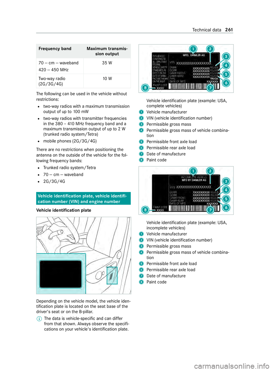
Ve hicle identi fication pla te Depending on
theve hicle model, theve hicle iden‐
tification plate is located on the seat base of the
driver's seat or on the B-pillar.
% The data is
vehicle-specific and can dif fer
from that shown. Alw ays obser vethe specifi‐
cations on your vehicle's identification plate. Ve
hicle identification plate (e xample: US A,
comple te vehicles)
1 Vehicle manufacturer
2 VIN (vehicle identification number)
3 Perm issible gross mass
4 Perm issible gross mass of vehicle combina‐
tion
5 Perm issible front axle load
6 Perm issible rear axle load
7 Date of manufacture
8 Paint code Ve
hicle identification plate (e xample: US A,
incomple te vehicles)
1 Vehicle manufacturer
2 VIN (vehicle identification number)
3 Perm issible gross mass
4 Perm issible gross mass of vehicle combina‐
tion
5 Perm issible front axle load
6 Perm issible rear axle load
7 Date of manufacture
8 Paint code Te
ch nical da ta261