2019 MERCEDES-BENZ SPRINTER ABS
[x] Cancel search: ABSPage 4 of 354

Deutsch
Information zur Betriebsanleitung
Diese Er
gänzung ist Bes tandteil der gedruckten
und der digit alen Betriebsanleitung Sprinter.
Sie ersetzt dort im Kapitel „Fahren und Parken“ -
„A utomatik getriebe“ den Abschnitt „Par kstel‐
lung P einlegen“.
Be wa hren Sie diese Er gänzung zusammen mit der
Betriebsanleitung im Fahrzeug auf. Pa
rkstellung P einlegen #
Die Taste 1 drüc ken.
Im Multifunktionsdisplay zeigt die Getriebe‐
st ellungsanzeige auf 005D.
We nn eine der folgenden Bedingungen erfüllt ist,
wir d die Parkstellung 005Dautomatisch eingelegt:
R Sie stellen den Mo tor in der Getriebe stellung
005B oder 005Eab.
R Sie öffnen im Stills tand oder bei sehr geringer
Fa hrge schwindigkeit in der Getriebes tellung
005B oder 005Edie Fahrertür. English (UK)
Information on
the Operating Instructions This Supplement is part of
the printed and Digital
Spr inter Operating Instructions.
It re places the "Engaging park position P" section
in thech ap ter on "Driving and parking" - "Auto‐
matic transmission".
Ke ep this Supplement in theve hicle toge ther with
th e Operating Instructions. Engaging park position P
#
Press button 1.
Tr ansmission position display 005Dis shown in
th e multifunction displa y.
Pa rk position 005Dis eng aged automatically when
one of thefo llowing conditions is me t:
R you swit choff the engine in transmission
position 005Bor005E.
R you open the driver's door when theve hicle is
st ationary or when driving at a very low speed
and in transmission position 005Bor005E. English (US)
Information on
the Operating Instructions This Supplement is part of
the printed and Digital
Spr inter Operating Instructions.
It re places the "Engaging park position P" section
in thech ap ter on "Driving and parking" - "Auto‐
matic transmission".
Ke ep this Supplement in theve hicle toget her with
th e Operating Instructions. 2
Page 31 of 354

Instrument Display (color dis‐
play)
1 Speedome ter →
16 3
2 00E5 ESP®
→
297
3 00BA Distance warning →
303
4 00E9 Seat belt not fastened →
302
5 003E003D Turn signal indica‐
to rs →
80
6 Multifunction display →
297
7 0077 Tire pressure loss warn‐
ing lamp →
297
8 00B9 Check Engine →
303
9 0028 Preglow and malfunction
in preglow sy stem
A Tach ome ter →
16 3
B 0049 and0024 (USA) or 0024
(Canada) parking brake is
applied (red) →
297
C 0027 and004D (USA) or 004D
(Canada) brakes (red) →
297 D
003D Electrical malfunction →
303
E Coolant temp erature indicator
and 00AC coolant too hot →
303
F 0024 Electri c parking brake
(yellow) →
297
G 0075 Restra int sy stem →
28
H 0057 High beam →
80
I 0058 Low beam →
79
J 0060 Parking lights →
79
K Fuel le vel indicator and 00D4
fuel reser vewith fuel filler cap
location indicator →
303
L Fo
g light →
79
M 005E Rear fog light →
79
N 004D Brakes (yellow) →
297
O 0025 ABS malfunction →
297
P 00BB ESP®
deactivated →
297 At
aglance – In stru ment clus ter7
Page 33 of 354

N
004D Brakes (yell ow) →
297
O 0025 ABS malfunction →
297
P 00BB ESP®
deactivated →
297 At
aglance – In stru ment clus ter9
Page 46 of 354
&
WARNING Risk offire due toflammable
materials on hot parts of theex haust sys‐
tem
Flammable material such as lea ves, grass or
twigs may ignite if they come into contact
wi th hot parts of theex haust sy stem. #
When driving on unpa vedro ads or off-
ro ad, regular lych eck theve hicle under‐
side. #
Remo vetrapped plants or other flam‐
mable material. #
Ifth ere is damage, consult a qualified
specialist workshop immediately. *
NO
TEDama getotheve hicle In
thefo llowing situations, in particular, there
is a risk of damage totheve hicle:
R The vehicle becomes grounded, e.g. on a
high curb or an unpa vedro ad
R The vehicle is driven toofast over an
obs tacle, e.g. a curb, speed bu mpor pot‐
hole
R A heavy object strike sth e underbody or
ch assis components
In situations such as this, the body, the
underbody, chassis components, wheels or
tires could be damaged without the damage
being visible. Components damaged in this
wa y can unexpectedly fail or, in the case of an
accident, may not absorb the loads that arise
as intended.
If th e underbody paneling is damaged, flam‐
mable materials such as lea ves, grass or
twigs can collect between the underbody and
th e underbody paneling. These materials may
ignite if they come into contact wi thhot parts
on theex haust sy stem. #
Have theve hicle checked and repaired
immediately at a qualified specialist
wo rkshop.
or #
If driving saf ety is impaired while con‐
tinuing your journe y,pull over and stop
th eve hicle immediately in accordance
with the traf fic conditions, and contact
a qu alified specialist workshop. Declarations of conformity
Information about
the decla ration of conform‐
ity for wi reless vehicle components USA:
"The wireless devices of this vehicle comply
with Part15 ofthe FCC Rules. Operation is sub‐
ject tothefo llowing two conditions: 1) These
devices may not cause harmful inter fere nce, and
2) These devices must acce ptany inter fere nce
re ceived, including inter fere nce that may cause
undesired operation. Changes or modi fications
not expressly appr ovedby the party responsible
fo r compliance could void the user's authority to
operate the equipment."
Canada: "The wireless devices of this vehicle
comply with Industry Canada license-e xemp t RSS
st andard(s). Operation is subject tothefo llowing
two conditions: (1) These devices may not cause
inter fere nce, and (2) These devices must acce pt
any inter fere nce, including inter fere nce that may
cause undesired operation of the device."
USA: "Wireless charging sy stem for mobile devi‐
ces (model: WMI2 Wireless Mobile Inter face): this
device complies with Part18 ofthe FCC Rules."
The name and address of there sponsible party
is:
peiker acustic GmbH
Max-Planc k-St r.28-32
61 381 Friedrichsdorf
Germany Diagnostics connection
The diagnostics connection is only intended for
th e connection of diagnostic devices at a quali‐
fi ed specialist workshop. &
WARNING Risk of accident due tocon‐
necting devices tothe diagnostics con‐
nection
If yo u connect equipment toa diagnostics
connection in theve hicle, it may af fect the
operation of vehicle sy stems.
As a result, the operating saf ety of theve hicle
could be af fected. #
Only connect equipment toa diagnos‐
tics connection in theve hicle which is
appr ovedfo ryo ur vehicle byMercedes-
Benz. 22
General no tes
Page 90 of 354
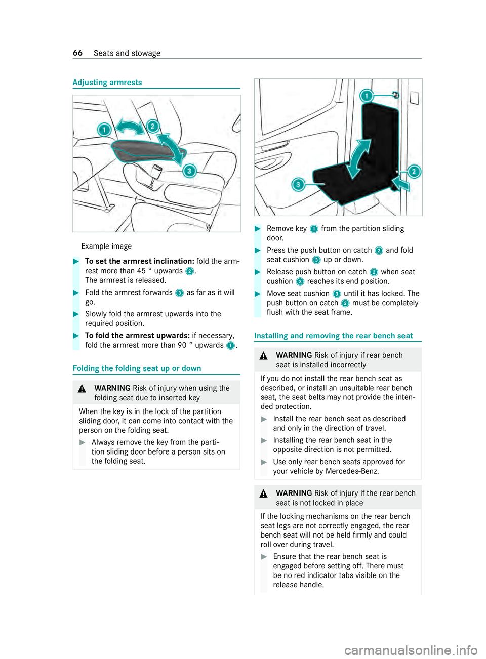
Ad
justing armrests Example ima
ge #
Toset the armrest inclination: fold the arm‐
re st more than 45 ° upwards 2.
The armrest is released. #
Foldthe armrest forw ards 3asfar as it will
go. #
Slowly fold the armrest upwards into the
re qu ired position. #
Tofold the armrest up wards: if necessar y,
fo ld the armrest more than 90 ° upwards 1. Fo
lding thefo lding seat up or down &
WARNING Risk of inju rywhen using the
fo lding seat due toinser tedkey
When theke y is in the lock of the partition
sliding door, it can come into contact with the
person on thefo lding seat. #
Alwaysre mo vetheke y from the parti‐
tion sliding door before a person sits on
th efo lding seat. #
Remo vekey1 from the partition sliding
door. #
Press the push button on catch 2and fold
seat cushion 3up or down. #
Release push button on cat ch2 when seat
cushion 3reaches its end position. #
Moveseat cushion 3until it has loc ked. The
push button on catch 2must be comple tely
fl ush with the seat frame. Installing and
removing the rear ben chseat &
WARNING Risk of inju ryifre ar ben ch
seat is ins talled incor rectly
If yo u do not ins tallth ere ar ben chseat as
described, or ins tall an unsuitable rear ben ch
seat, the seat belts may not pr ovide the inten‐
ded pr otection. #
Installth ere ar ben chseat as described
and only in the direction of tra vel. #
Installing there ar ben chseat in the
opposite direction is not permitted. #
Use only rear ben chseats appr ovedfor
yo ur vehicle byMercedes-Benz. &
WARNING Risk of inju ryifth ere ar ben ch
seat is not loc ked in place
If th e locking mechanisms on there ar ben ch
seat legs are not cor rectly engaged, there ar
ben chseat will not be held firm lyand could
ro llove r during tr avel. #
Ensure that there ar ben chseat is
engaged before setting off. There must
be no red indicator tabs visible on the
re lease handle. 66
Seats and stowage
Page 91 of 354
#
Ifre d indicator tabs are visible on the
re lease handle, re-engage there ar
ben chseat into place. &
WARNING Risk of inju rywhen ins talling
and removing there ar ben chseat
When you ins tall or remo vethere ar ben ch
seat, body parts such as feet may become
trapped when there ar ben chseat is tipped. #
When ins talling and removing there ar
ben chseat, ensure that there are no
body parts between there ar ben chseat
and thefloor. *
NO
TEDama getorear ben chseat rollers
caused byincor rect use The
rear ben chseat rollers can be damaged if
th ere ar ben chseat is used improperly or is
re mo ved incor rectl y. #
As long as there ar ben chseat is in the
mounting shells, do not pull these in the
direction of there ar-end doors. Rollthe
re ar ben chseat only beside the mount‐
ing shells. #
Do not rollth ere ar ben chseat when it
has been remo ved or use it as a means
of transport. Wa
rning on rear ben chseat with cor rectly
ins talled rear ben chseat shown.
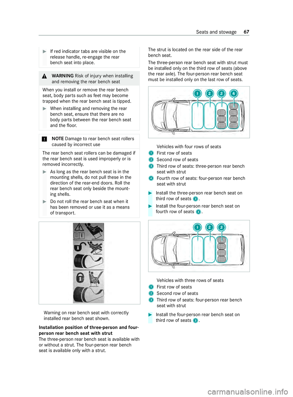
Installation position of three-person and four-
person rear ben chseat with strut
The thre e-person rear ben chseat is available with
or without a stru t. The four-pe rson rear ben ch
seat is available only with a stru t. The
stru t is located on there ar side of there ar
ben chseat.
The thre e-person rear ben chseat with stru t mu st
be ins talled only on theth ird row of seats (abo ve
th ere ar axle). The four-pe rson rear ben chseat
must be ins talled only on the last rowof seats. Ve
hicles with four rows of seats
1 Firstrow of seats
2 Second rowof seats
3 Third rowof seats: thre e-person rear ben ch
seat with strut
4 Fourth row of seats: four-pe rson rear ben ch
seat with strut #
Installth eth re e-person rear ben chseat on
th ird row of seats 3. #
Installth efo ur-pe rson rear ben chseat on
fo ur th row of seats 4. Ve
hicles with thre erow s of seats
1 Firstrow of seats
2 Second rowof seats
3 Third rowof seats: four-pe rson rear ben ch
seat with strut #
Installth efo ur-pe rson rear ben chseat on
th ird row of seats 3. Seats and
stowage 67
Page 92 of 354
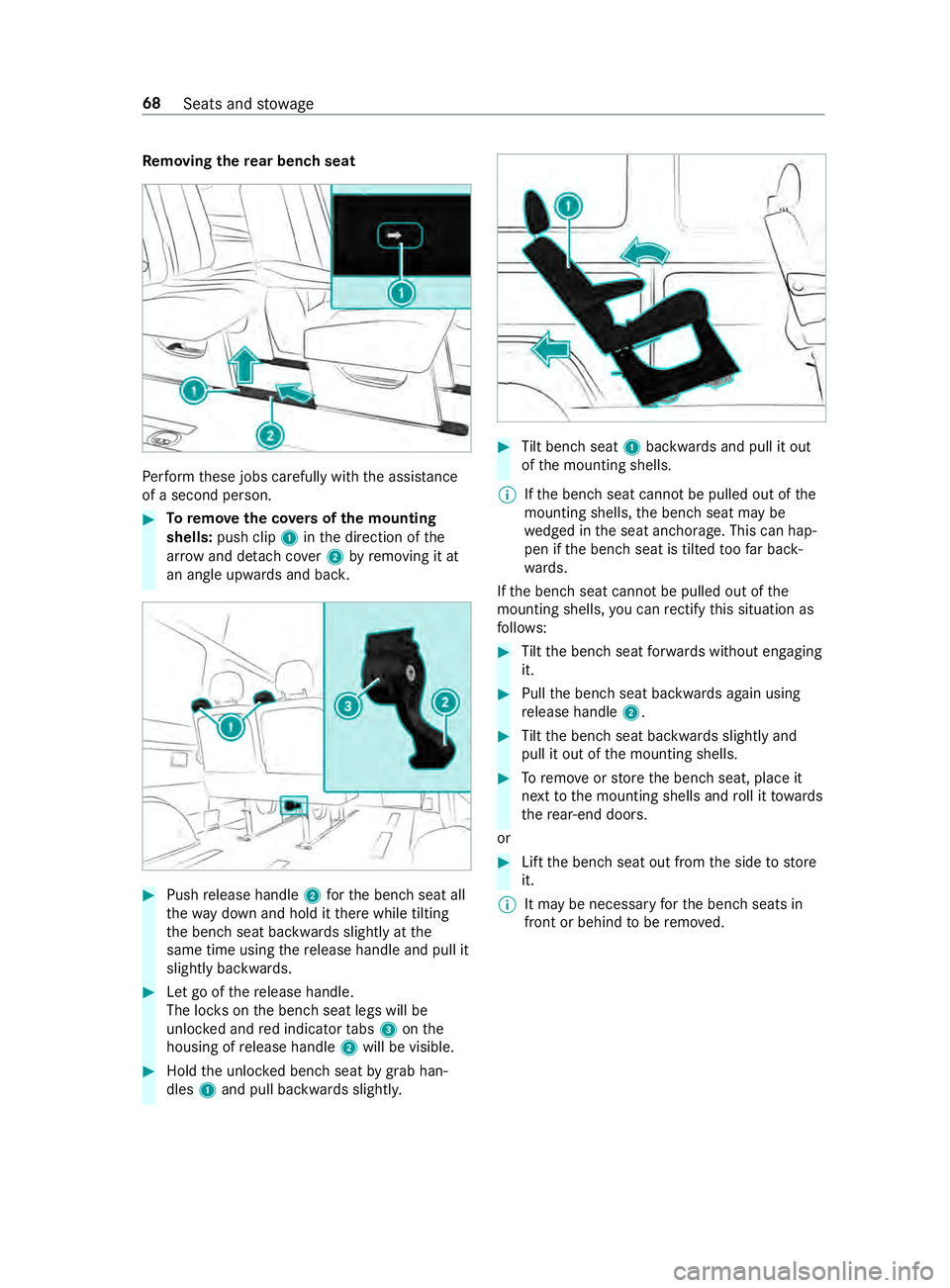
Re
moving the rear ben chseat Pe
rform these jobs carefully with the assis tance
of a second pe rson. #
Toremo vethe co vers of the mounting
shells: push clip 1inthe direction of the
ar row and de tach cover2 byremoving it at
an angle upwards and bac k.#
Push release handle 2forth e bench seat all
th ewa y down and hold it there while tilting
th e bench seat backwards slightly at the
same time using there lease handle and pull it
slightly backwards. #
Let go of there lease handle.
The loc kson the bench seat legs will be
unloc ked and red indicator tabs 3 onthe
housing of release handle 2will be visible. #
Hold the unloc ked bench seat bygrab han‐
dles 1and pull backwards slightl y. #
Tilt bench seat 1backwards and pull it out
of the mounting shells.
% If
th e bench seat cann otbe pulled out of the
mounting shells, the bench seat may be
we dged in the seat anchorage. This can hap‐
pen if the bench seat is tilted toofa r back‐
wa rds.
If th e bench seat cann otbe pulled out of the
mounting shells, you can rectify this situation as
fo llo ws: #
Tilt th e bench seat forw ards without engaging
it. #
Pull the bench seat backwards again using
re lease handle 2. #
Tilt th e bench seat backwards slightly and
pull it out of the mounting shells. #
Toremo veorstore the bench seat, place it
next tothe mounting shells and roll it towa rds
th ere ar-end doors.
or #
Lift the bench seat out from the side tostore
it.
% It may be necessary
forth e bench seats in
front or behind tobe remo ved. 68
Seats and stowage
Page 93 of 354
#
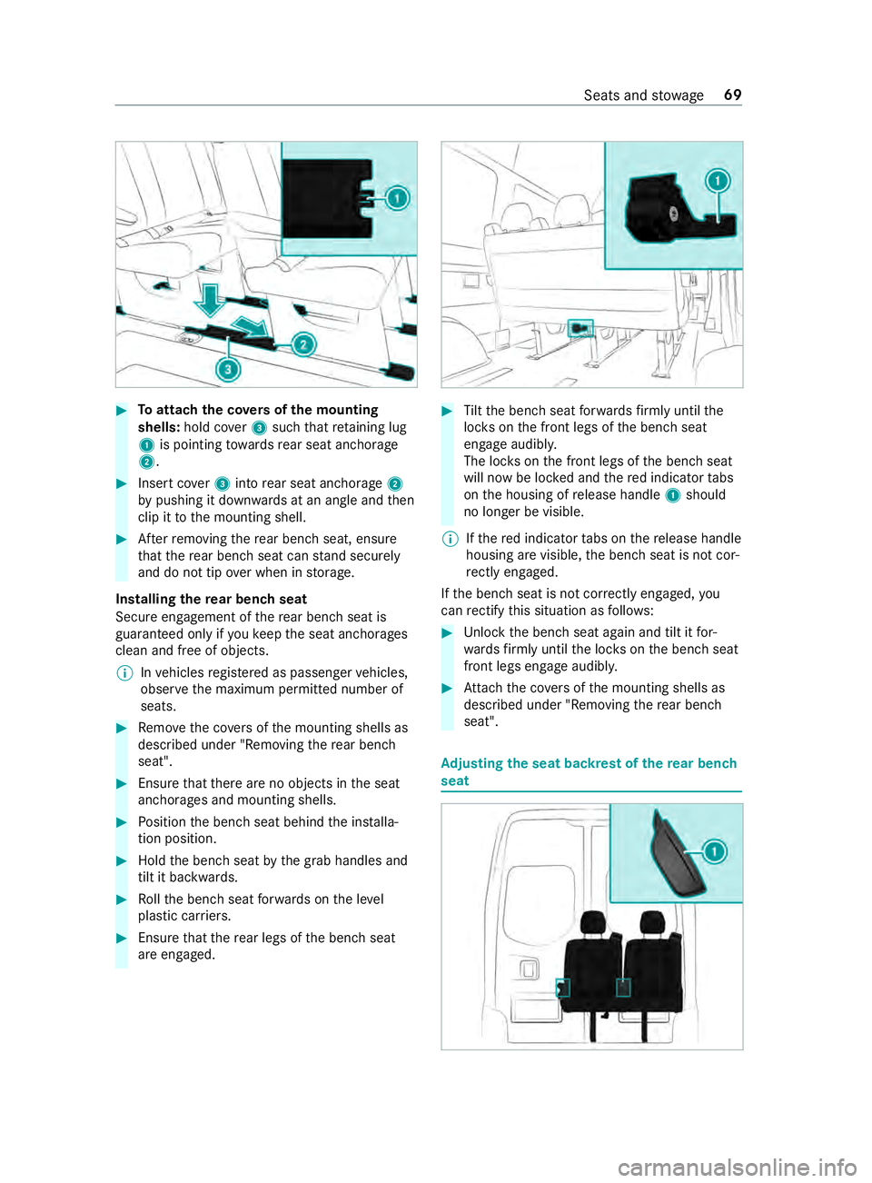
Toattach the co vers of the mounting
shells: hold cover3 such that retaining lug
1 is pointing towa rdsre ar seat anchorage
2. #
Insert co ver3 into rear seat anchorage 2
by pushing it down wards at an angle and then
clip it tothe mounting shell. #
Afterre moving there ar ben chseat, ensure
th at there ar ben chseat can stand securely
and do not tip over when in storage.
Installing there ar ben chseat
Secure engagement of there ar ben chseat is
guaranteed only if youke ep the seat anchorages
clean and free of objects.
% In
vehicles regis tere d as passenger vehicles,
obser vethe maximum permitted number of
seats. #
Remo vethe co vers of the mounting shells as
described under "Removing there ar ben ch
seat". #
Ensure that there are no objects in the seat
anchorages and mounting shells. #
Position the bench seat behind the ins talla‐
tion position. #
Hold the bench seat bythe grab handles and
tilt it backwards. #
Rollth e bench seat forw ards on the le vel
plastic car riers. #
Ensure that there ar legs of the bench seat
are engaged. #
Tilt th e bench seat forw ards firm lyuntil the
loc kson the front legs of the bench seat
engage audibly.
The loc kson the front legs of the bench seat
will now be loc ked and there d indicator tabs
on the housing of release handle 1should
no longer be visible.
% If
th ere d indicator tabs on there lease handle
housing are visible, the bench seat is not cor‐
re ctly engaged.
If th e bench seat is not cor rectly engaged, you
can rectify this situation as follo ws: #
Unlock the bench seat again and tilt it for‐
wa rdsfirm ly until the loc kson the bench seat
front legs engage audibly. #
Attach the co vers of the mounting shells as
described under "Removing there ar ben ch
seat". Ad
justing the seat backrest of the rear ben ch
seat Seats and
stowage 69