2019 MERCEDES-BENZ S CLASS change wheel
[x] Cancel search: change wheelPage 442 of 578

The systemchecksthe tire pressure andthe tiretemperature ofthe tires installed onthevehiclebymeans of a tire pressuresensor.
New tire pressure sensors, e.g. in winter tires,are automaticallytaught-in duringthefirst jour‐neytheyare used.
The tire pressure appears inthe multifunctiondisplay (→page 255).
Ifthere is a substantial pressure loss or ifthetiretemperature isexcessive,you will bewarnedinthefollowingways:
Rvia display messages (→page511)
Rviathe�wwarning lamp inthe instrumentcluster (→page 533)
The tire pressuremonitoring system is only anaid. It isthe driver'sresponsibilitytosetthe tirepressuretotherecommended cold tire pressuresuitableforthe operating situation. Setthe tirepressurefor cold tires using a tire pressuregauge. Notethatthe correct tire pressureforthecurrent operating situation mustfirst betaught-intothe tire pressure monitoring system.
In most cases,the tire pressure monitoring sys‐tem will automatically updatethe newreferencevalues afteryou havechangedthe tire pressure.You can, however,also updatethereferenceval‐uesbyrestartingthe tire pressure monitoringsystem manually (→page441).
System limitations
The system may be impaired or may not functioninthefollowing situations:
RIfthe tire pressure is set incorrectly
RIfthere is a sudden pressure loss caused,forexample,byaforeign object penetratingthetire
RIfthere is a malfunction causedbyanotherradio signal source
Make suretoobservethefollowing furtherrela‐ted subject:
RNotes on tire pressure (→page 435)
Checkingthe tire pressure withthe tire pres‐sure monitoring system
Requirements:RThe ignition is switched on.
On-board computer:
,Service.Tires
One ofthefollowing displaysappears:
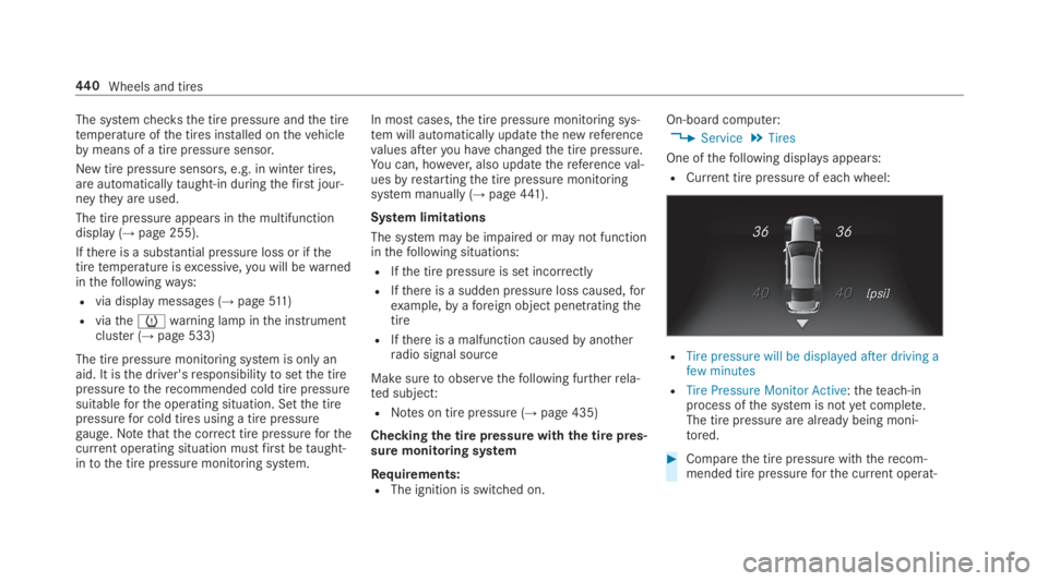
RCurrent tire pressure of eachwheel:
RTire pressure will be displayed after driving afew minutes
RTire Pressure Monitor Active:theteach-inprocess ofthe system is notyet complete.The tire pressure are already being moni‐tored.
#Comparethe tire pressure withtherecom‐mended tire pressureforthe current operat‐
440Wheels and tires
Page 443 of 578

ing condition (→page 437). Observethenotes on tiretemperature (→page 435).
%Thevalues displayed inthe multifunction dis‐play may deviate fromthose ofthe tire pres‐suregauge astheyrefertosea level.Athighaltitudes,the tire pressurevalue indicatedbya pressuregauge are higherthanthoseshownbythe on-board computer. Inthiscase, do notreducethe tire pressure.
Make suretoobservethefollowing furtherrela‐ted subject:
RNotes on tire pressure (→page 435)
Restartingthe tire pressure monitoring sys‐tem
Requirements:RTherecommended tire pressure is correctlysetfortherespective operating condition oneach ofthefour wheels (→page 435).
Restartthe tire pressure monitoring system inthefollowing situations:
RThe tire pressure haschanged.
RThe wheels or tires havebeenchanged ornewly installed.
On-board computer:
,Service.Tires
#Swipe downwards onTouch Control ontheleft-hand side ofthesteering wheel.TheUse Current Pressures as New Refer-ence Values?message is shown inthe multi‐function display.
#Press�vtoconfirmtherestart.TheRun Flat Indicator Restartedmessage isshown inthe multifunction display.
Currentwarning messages are deleted andthe�wyellowwarning lamp goes out.
Afteryou havedrivenfor afew minutes,thesystemcheckswhetherthe current tire pres‐sures are withinthe specifiedrange. The cur‐rent tire pressures arethen accepted asref‐erencevalues and monitored.
Make suretoobservethefollowing furtherrela‐ted subject:
RNotes on tire pressure (→page 435)
Radio equipment approval ofthe tire pres‐sure monitoring system
Radio equipment approval numbers
CountryRadio type approval number
Canada IC: 2546A-GG4T
IC: 2546A-DG6W2D4
IC: 2546A-MC34MA4
Le présent appareil est conformeaux CNR d'Industrie Canadaapplicables aux appareilsradioexempts de licence. L'exploita‐tion est autorisée aux deux con‐ditions suivantes:
(1) l'appareil ne doit pas produirede brouillage,et
(2) l'utilisateur de l'appareil doitacceptertout brouillageradioé‐lectrique subi, même si le
brouillage est susceptible d'encompromettrelefonctionnement.
Wheels and tires441
Page 457 of 578

Only use tires, wheels and accessoriesthathavebeenchecked andrecommendedbyMercedes-Benz.
*NOTERisktodriving safety fromretrea‐ded tires
Retreaded tires are neithertested norrecom‐mendedbyMercedes-Benz, since previousdamage cannot always be detected onretreaded tires.
Forthisreason driving safety cannot be guar‐anteed.
#Do not use used tires ifyou havenoinformation abouttheir previous usage.
*NOTEPossible damagetowheels or tireswhen drivingover obstacles
Large wheels havea lower tire section width.The lowerthe tire section width,the greateristherisk of damagetowheels or tires whendrivingover obstacles.
#Avoid obstacles or drive particularlycarefully.
*NOTEDamagetoelectronic componentparts fromthe use of tire-mountingtools
Vehicles with a tire pressure monitoringsystem:Electronic component parts arelocated inthe wheel.Tire-mountingtoolsshould not be used inthe area ofthevalve.
This couldotherwise damagethe electroniccomponent parts.
#Havethe tireschanged at aqualifiedspecialistworkshop only.
*NOTEDamagetosummer tires at lowambienttemperatures
Atlow ambienttemperatures,tears couldformwhen driving with summer tires, caus‐ing permanent damagetothe tires.
#Attemperatures below 45 °F (7 °C),use M+S tires .
Accessory partsthat are not approvedforyourvehiclebyMercedes-Benz or are not being usedcorrectly can impairthe operating safety.
Before purchasing and using non-approvedaccessories, visit aqualified specialistworkshopand inquire about:
RSuitability
RLegalstipulations
RFactoryrecommendations
&WARNINGRisk of accident withhighperformance tires
The special tire tread in combination withtheoptimized tire compound meansthattheriskof skidding orhydroplaning onwetroads isincreased.
In addition,the tire grip is greatlyreduced ata low outsidetemperature and tirerunningtemperature.
#Switch onthe ESP®and adaptyourdrivingstyle accordingly.
#Use M+S tire at outsidetemperaturesof lessthan10°C (50 °F).
Wheels and tires455
Page 459 of 578

Thewear patterns onthe front andrear wheelsdiffer:
RFront wheelswear more onthe shoulder ofthe tire
RRear wheelswear more inthe center ofthetire
Onvehiclesthat havethe same size front andrear wheels,rotatethe wheels accordingtotheintervals inthe tire manufacturer'swarrantybook inyourvehicle documents. Ifthis is notavailable,rotatethe tiresevery3,000to6,000 miles (5,000to10,000 km),depending onthewear. Ensurethatthe directionofrotation is maintained.
It is imperativetoobservethe instructions andsafety notes on "Changing a wheel" when doingso Preparingthevehiclefor a wheelchange(→page 458).
Notes onstoring wheels
Whenstoring wheels, observethefollowingnotes:
RAfterremoving wheels,storethem in a cool,dry and preferably dark place.
RProtectthe tires from contact withoil, greaseor fuel.
Overview ofthe tire-changetool kit
Apart from some country-specificvariants,vehi‐cles are not equipped with a tire-changetool kit.For more information on whichtire-changetoolsarerequired and approvedfor performing awheelchange onyourvehicle, consult aqualifiedspecialistworkshop.
Required tire-changetools may include,forexample:
RJack
RChock
RLug wrench
RAlignment bolt
The tire-changetool kit is located underthetrunkfloor.
1Ratchet
2Alignment bolt
3Jacking support
4Jack
5Lug wrench
6Foldingchock
Wheels and tires457
Page 460 of 578

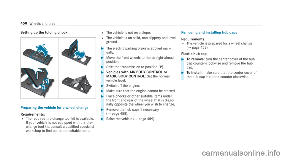
Setting upthefoldingchock
Preparingthevehiclefor a wheelchange
Requirements:RTherequired tire-changetool kit isavailable.Ifyourvehicle is not equipped withthe tire-changetool kit, consult aqualified specialistworkshoptofind out about suitabletools.
RThevehicle is not on a slope.
RThevehicle is on solid, non-slippery and levelground.
#The electric parking brake is applied man‐ually.
#Movethe front wheelstothestraight-aheadposition.
#Shiftthe transmissiontoposition�].
#Vehicles with AIRBODYCONTROL orMAGICBODYCONTROL:Setthe normalvehicle level.
#Switchoffthe engine.
#Make surethatthe engine cannotbestarted.
#Placechocksorother suitable items underthe front andrear ofthe wheelthat is diago‐nally oppositethe wheelyou wishtochange.
#Removethe hub caps if necessary(→page 458).
#Raisethevehicle (→page 459).
Removing and installing hub caps
Requirements:RThevehicle is preparedfor a wheelchange(→page 458).
Plastic hub cap
#Toremove:turnthe center cover ofthe hubcap counter-clockwise andremovethe hubcap.
#Toinstall:make surethatthe center cover ofthe hub cap is turned counter-clockwise.
458Wheels and tires
Page 461 of 578

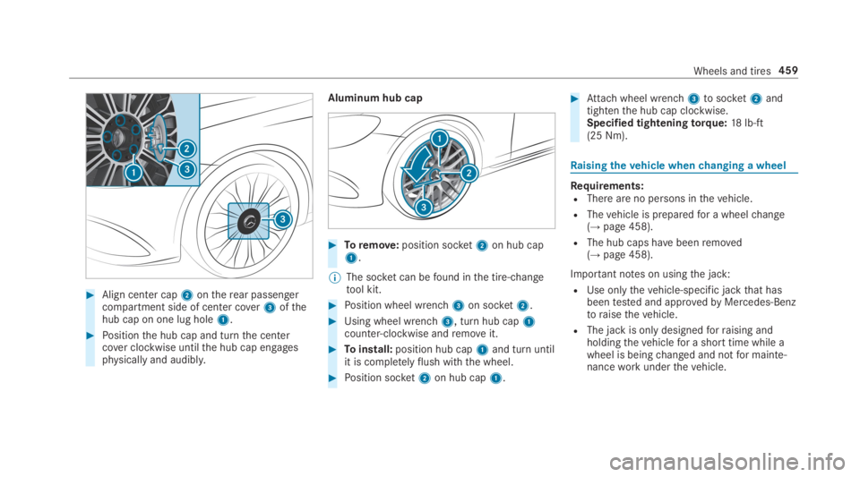
#Align center cap2ontherear passengercompartment side of center cover3ofthehub cap on one lug hole1.
#Positionthe hub cap and turnthe centercover clockwise untilthe hub cap engagesphysically and audibly.
Aluminum hub cap
#Toremove:position socket2on hub cap1.
%The socket can befound inthe tire-changetool kit.
#Position wheel wrench3on socket2.
#Using wheel wrench3, turn hub cap1counter-clockwise andremoveit.
#Toinstall:position hub cap1and turn untilit is completelyflush withthe wheel.
#Position socket2on hub cap1.
#Attachwheel wrench3tosocket2andtightenthe hub cap clockwise.Specified tighteningtorque:18lb-ft(25 Nm).
Raisingthevehicle whenchanging a wheel
Requirements:RThere are no persons inthevehicle.
RThevehicle is preparedfor a wheelchange(→page 458).
RThe hub caps havebeenremoved(→page 458).
Important notes on usingthe jack:
RUse onlythevehicle-specific jackthat hasbeentested and approvedbyMercedes-Benztoraisethevehicle.
RThe jack is only designedforraising andholdingthevehiclefor a short time while awheel is beingchanged and notfor mainte‐nanceworkunderthevehicle.
Wheels and tires459
Page 462 of 578

RThe jack must be placed on afirm,flat andnon-slip surface. If necessary,use a large,flat, load-bearing, non-slip underlay.
RThefootofthe jack must be positionedverti‐cally underthe jack support point.
Rules of conduct whenthevehicle israised:
RNever placeyour hands orfeetunderthevehicle.
RNever lie underthevehicle.
RDo notstartthe engine and do notreleasethe electric parking brake.
RDo not open or close any doors orthe trunklid.
#Usingthe lug wrench, loosenthe wheel boltsonthe wheelyou wishtochangebyaboutone full turn. Do not unscrewthe bolts com‐pletely.
Position of jack support points
&WARNINGRisk of injuryfrom incorrectpositioning ofthe jack
Ifyou do not positionthe jack correctly atthe appropriate jacking point ofthevehicle,the jack could tip withthevehicleraised.
#Only positionthe jack atthe appropri‐ate jacking point ofthevehicle. Thebase ofthe jack must be positionedver‐tically underthe jacking point ofthevehicle.
460Wheels and tires
Page 463 of 578

*NOTEVehicle damage fromthe jack
Ifyou do not positionthe jack correctly atthe appropriate jack support point ofthevehicle,the jack could tipover withthevehi‐cleraised.
#The jack is designedexclusivelyforjacking upthevehicle atthe jack sup‐port points.
#Taketheratchet wrench out ofthe tire-changetool kit and place it onthe hexagonnut ofthe jack sothatthe letters "AUF" arevisible.
#Position jack2at jack support point1.
#Turnratchet wrench3clockwise until jack2sits completelyon jack support point1andthe base ofthe jack liesevenly ontheground.
#Continuetoturnratchet wrench3untilthetire israised a maximum of1.2 in (3 cm) offthe ground.
#Loosen andremovethe wheel (→page 461).
Removing a wheel
Requirements:RThevehicle israised (→page 459).
Mercedes-AMGvehicles:observethe notes inthe Supplement. Otherwise,you may notrecog‐nize dangers.
Whenchanging a wheel,avoid applying anyforcetothe brake discs, sincethis could impairthelevel of comfortwhen braking.
*NOTEDamagetothreading from dirt onwheel bolts
#Do not place wheel bolts in sand or ona dirty surface.
#Unscrewthe uppermost wheel bolt com‐pletely.
Wheelsand tires461