2019 MERCEDES-BENZ GLS SUV inflation pressure
[x] Cancel search: inflation pressurePage 362 of 398

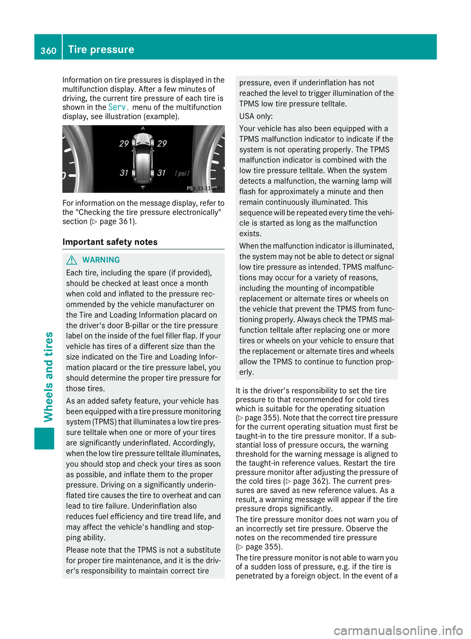
Information on tire pressures is displayed in the
multifunction display. After a few minutes of
driving, the current tire pressure of each tire is
shown in the Serv.
Serv. menu of the multifunction
display, see illustration (example). For information on the message display, refer to
the "Checking the tire pressure electronically"
section (Y page 361).
Important safety notes G
WARNING
Each tire, including the spare (if provided),
should be checked at least once a month
when cold and inflated to the pressure rec-
ommended by the vehicle manufacturer on
the Tire and Loading Information placard on
the driver's door B-pillar or the tire pressure
label on the inside of the fuel filler flap. If your vehicle has tires of a different size than the
size indicated on the Tire and Loading Infor-
mation placard or the tire pressure label, you should determine the proper tire pressure for
those tires.
As an added safety feature, your vehicle has
been equipped with a tire pressure monitoring system (TPMS) that illuminates a low tire pres-
sure telltale when one or more of your tires
are significantly underinflated. Accordingly,
when the low tire pressure telltale illuminates,
you should stop and check your tires as soon
as possible, and inflate them to the proper
pressure. Driving on a significantly underin-
flated tire causes the tire to overheat and can lead to tire failure. Underinflation also
reduces fuel efficiency and tire tread life, andmay affect the vehicle's handling and stop-
ping ability.
Please note that the TPMS is not a substitute
for proper tire maintenance, and it is the driv-
er's responsibility to maintain correct tire pressure, even if underinflation has not
reached the level to trigger illumination of the TPMS low tire pressure telltale.
USA only:
Your vehicle has also been equipped with a
TPMS malfunction indicator to indicate if the
system is not operating properly. The TPMS
malfunction indicator is combined with the
low tire pressure telltale. When the system
detects a malfunction, the warning lamp will
flash for approximately a minute and then
remain continuously illuminated. This
sequence will be repeated every time the vehi-
cle is started as long as the malfunction
exists.
When the malfunction indicator is illuminated,
the system may not be able to detect or signal low tire pressure as intended. TPMS malfunc-tions may occur for a variety of reasons,
including the mounting of incompatible
replacement or alternate tires or wheels on
the vehicle that prevent the TPMS from func-
tioning properly. Always check the TPMS mal-
function telltale after replacing one or more
tires or wheels on your vehicle to ensure that
the replacement or alternate tires and wheels
allow the TPMS to continue to function prop-
erly.
It is the driver's responsibility to set the tire
pressure to that recommended for cold tires
which is suitable for the operating situation
(Y page 355). Note that the correct tire pressure
for the current operating situation must first be
taught-in to the tire pressure monitor. If a sub-
stantial loss of pressure occurs, the warning
threshold for the warning message is aligned to the taught-in reference values. Restart the tire
pressure monitor after adjusting the pressure of
the cold tires (Y page 362). The current pres-
sures are saved as new reference values. As a
result, a warning message will appear if the tire
pressure drops significantly.
The tire pressure monitor does not warn you of
an incorrectly set tire pressure. Observe the
notes on the recommended tire pressure
(Y page 355).
The tire pressure monitor is not able to warn you of a sudden loss of pressure, e.g. if the tire is
penetrated by a foreign object. In the event of a 360
Tire pressureWheels and tires
Page 379 of 398

Lowering the vehicle
G
WARNING
The wheels could come loose if the wheel
bolts or wheel nuts are not tightened to the
prescribed tightening torque. There is a risk of an accident.
Ensure that the wheel bolts or wheel nuts are tightened to the prescribed tightening torque.
If you are not sure, do not move the vehicle.
Contact a qualified specialist workshop and
have the tightening torque checked immedi-
ately.
! Mercedes-AMG vehicles with a collapsi-
ble spare wheel: before lowering the vehicle,
inflate the collapsible spare wheel with the
tire inflation compressor. The wheel rim could
otherwise be damaged.
X Place the ratchet wrench onto the hexagon
nut of the jack so that the letters ABare visi-
ble.
X Turn the ratchet wrench until the vehicle is
once again standing firmly on the ground.
X Place the jack to one side. X
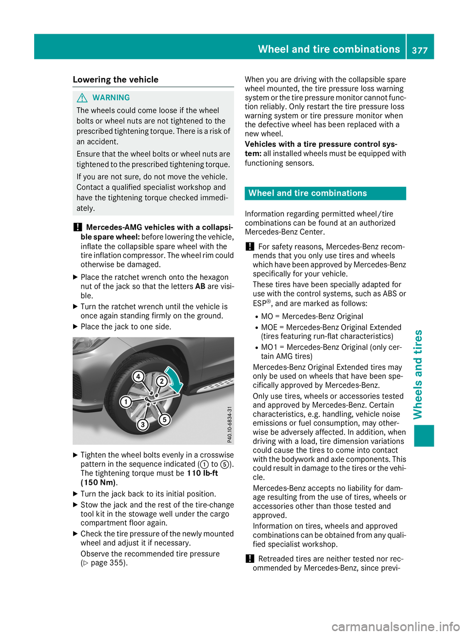
Tighten the wheel bolts evenly in a crosswise
pattern in the sequence indicated (0043 to0083).
The tightening torque must be 110 lb-ft
(150 Nm) .
X Turn the jack back to its initial position.
X Stow the jack and the rest of the tire-change
tool kit in the stowage well under the cargo
compartment floor again.
X Check the tire pressure of the newly mounted
wheel and adjust it if necessary.
Observe the recommended tire pressure
(Y page 355). When you are driving with the collapsible spare
wheel mounted, the tire pressure loss warning
system or the tire pressure monitor cannot func- tion reliably. Only restart the tire pressure loss
warning system or tire pressure monitor when
the defective wheel has been replaced with a
new wheel.
Vehicles with a tire pressure control sys-
tem: all installed wheels must be equipped with
functioning sensors. Wheel and tire combinations
Information regarding permitted wheel/tire
combinations can be found at an authorized
Mercedes-Benz Center.
! For safety reasons, Mercedes-Benz recom-
mends that you only use tires and wheels
which have been approved by Mercedes-Benz specifically for your vehicle.
These tires have been specially adapted for
use with the control systems, such as ABS or
ESP ®
, and are marked as follows:
R MO = Mercedes-Benz Original
R MOE = Mercedes-Benz Original Extended
(tires featuring run-flat characteristics)
R MO1 = Mercedes-Benz Original (only cer-
tain AMG tires)
Mercedes-Benz Original Extended tires may
only be used on wheels that have been spe-
cifically approved by Mercedes-Benz.
Only use tires, wheels or accessories tested
and approved by Mercedes-Benz. Certain
characteristics, e.g. handling, vehicle noise
emissions or fuel consumption, may other-
wise be adversely affected. In addition, when
driving with a load, tire dimension variations
could cause the tires to come into contact
with the bodywork and axle components. This
could result in damage to the tires or the vehi- cle.
Mercedes-Benz accepts no liability for dam-
age resulting from the use of tires, wheels or
accessories other than those tested and
approved.
Information on tires, wheels and approved
combinations can be obtained from any quali-fied specialist workshop.
! Retreaded tires are neither tested nor rec-
ommended by Mercedes-Benz, since previ- Wheel and tire combinations
377Wheels and tires Z
Page 383 of 398

compartment with the carrying strap at the
back.
X Hook retaining spring hooks 0043of fastening
strap 0044into the cargo tie-down rings.
X Tighten fastening strap 0044.Inflating the collapsible spare wheel
(Mercedes-AMG GLS 63 4MATIC)
! Inflate the collapsible spare wheel using the
tire inflation compressor before lowering the
vehicle. The wheel rim could otherwise be
damaged.
! Do not operate the tire inflation compressor
for longer than eight minutes at a time without
a break. It may otherwise overheat.
The tire inflation compressor can be operated again once it has cooled down.
Comply with the manufacturer's safety instruc-
tions on the tire inflation compressor label and
on the tire sealant bottle.
X Mount the collapsible spare wheel as descri-
bed (Y page 373).
The collapsible spare wheel must be mounted before it is inflated.
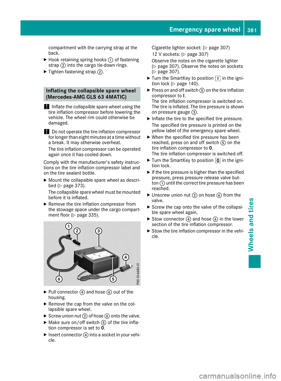
X Remove the tire inflation compressor from
the stowage space under the cargo compart-
ment floor (Y page 335). X
Pull connector 0085and hose 0084out of the
housing.
X Remove the cap from the valve on the col-
lapsible spare wheel.
X Screw union nut 0044of hose 0084onto the valve.
X Make sure on/off switch 0083of the tire infla-
tion compressor is set to 0.
X Insert connector 0085into a socket in your vehi-
cle. Cigarette lighter socket: (Y
page 307)
12 V sockets: (Y page 307)
Observe the notes on the cigarette lighter
(Y page 307). Observe the notes on sockets
(Y page 307).
X Turn the SmartKey to position 0047in the igni-
tion lock (Y page 140).
X Press on and off switch 0083on the tire inflation
compressor to I.
The tire inflation compressor is switched on.
The tire is inflated. The tire pressure is shown on pressure gauge 0087.
X Inflate the tire to the specified tire pressure.
The specified tire pressure is printed on the
yellow label of the emergency spare wheel.
X When the specified tire pressure has been
reached, press on and off switch 0083on the
tire inflation compressor to 0.
The tire inflation compressor is switched off.
X Turn the SmartKey to position 0092in the igni-
tion lock.
X If the tire pressure is higher than the specified
pressure, press pressure release valve but-
ton 0043until the correct tire pressure has been
reached.
X Unscrew union nut 0044on hose 0084from the
valve.
X Screw the cap onto the valve of the collapsi-
ble spare wheel again.
X Stow connector 0085and hose 0084in the lower
section of the tire inflation compressor.
X Stow the tire inflation compressor in the vehi-
cle. Emergency spare wheel
381Wheels and tires Z